Stephen L. Herman, Bennie Sparkman. Electricity and Controls for HVAC-R (6th edition)
Подождите немного. Документ загружается.

420 SECTION 7 Ice Maker and Refrigeration Controls
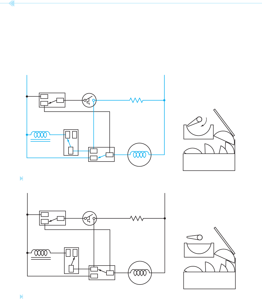
Near the completion of the second revolution,
Figure 45–11, the timing cam again closes the
water solenoid switch. A current path now exists
through the solenoid coil and the mold heater.
Although the solenoid coil and mold heater are now
connected in series, the impedance of the solenoid
coil is much higher than that of the heater. This per-
mits most of the voltage, about 105 to 110 volts, to
be applied across the coil causing it to energize and
open the water valve.
The cycle ends when the timing cam reopens the
water solenoid and holding switch, Figure 45–12. If
the storage bin is full as shown in this illustration, a
new ejection and re ll cycle cannot begin until suf -
cient ice has been removed from the storage bin to per-
mit the shutoff arm to return to its normal position.
NO
NONC
NO
NONC
NO
C
WATER
SOLENOID
VALVE
WATER
SOLENOID
SWITCH
HOLDING SWITCH
SHUTOFF SWITCH
THERMOSTAT
117 VOLTS
60 Hz
MOLD HEATER
MOTOR
SHUT-
OFF
ARM
C
NC
C
STORAGE BIN
NO
NONC
NO
NONC
NO
C
WATER
SOLENOID
VALVE
WATER
SOLENOID
SWITCH
HOLDING SWITCH
SHUTOFF SWITCH
THERMOSTAT
117 VOLTS
60 Hz
MOLD HEATER
MOTOR
SHUT-
OFF
ARM
C
NC
C
STORAGE BIN
WATER
Figure 45–11
End of the second revolution. (Source: Delmar/Cengage Learning)
Figure 45–12
End of the cycle. (Source: Delmar/Cengage Learning)
UNIT 45 Household Ice Makers 421
THE NEW MODEL COMPACT ICE
MAKER
Although the new model compact ice maker,
Figure 45–13, is very similar in design and operat-
ing principle to the original version just discussed,
there are some signi cant differences. Some of these
differences are listed below:
1. The ejector blades on the newer model stop at
a different position, as shown in Figure 45–14.
Also shown in Figure 45–14 is the position of
the ejector blades when different actions occur
during the ejection cycle.
2. The ejector blades make only one revolution
instead of two during the ejection cycle.
3. Most of the new models have an external
water level adjustment knob, Figure 45–13.
Turning the knob moves a set of contacts in
relation to its contact ring, permitting the ll
time to be longer or shorter.
4. On the original model compact ice maker, the
gear located on the front of the unit could be
turned manually to advance the ice maker
through different parts of the cycle. This
gear should never be turned on the newer
model. To do so will cause damage to the ice
maker. The front gears of both the original
and newer compact ice makers are shown in
Figure 45–15.
EJECTOR
BLADES
STALL
ON ICE
THERMOSTAT
OPENS
STARTING
POSITION
WATER VALVE
OPENS
Figure 45–13
New compact ice maker. (Source: Delmar/Cengage Learning)
Figure 45–15
Front gears of the original (left) and newer model (right)
compact ice makers. (Source: Delmar/Cengage Learning)
Figure 45–14
Ejector blade positions on new model compact
ice maker. (Source: Delmar/Cengage Learning)
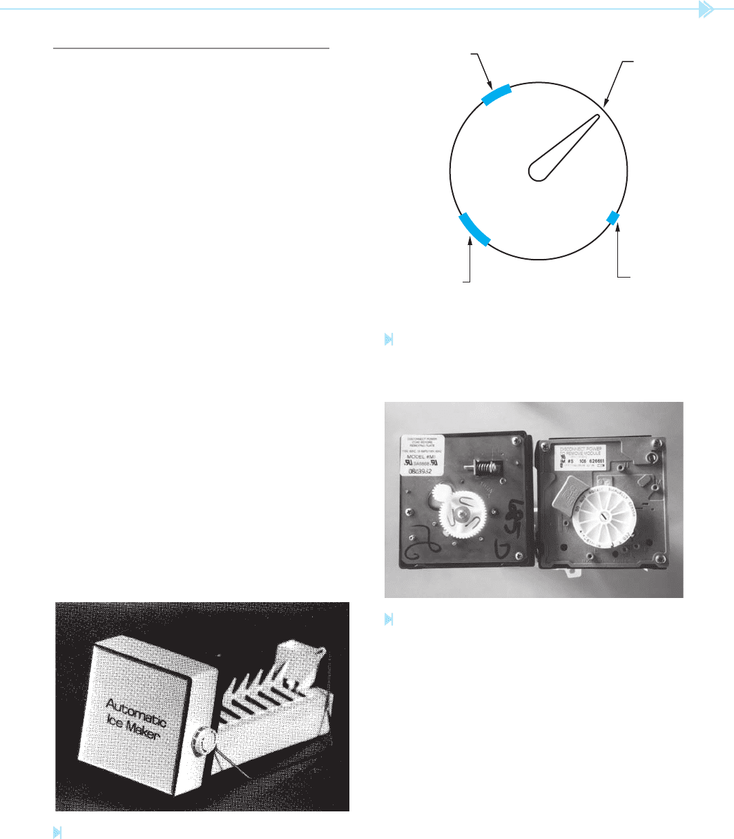
5. The new model compact provides test
points on the plate located behind the front
cover, Figure 45–16. It is possible to test
different parts of the electrical circuit using a
voltmeter and ohmmeter. The letters indicate
the following test points:
• N Neutral side of the line
• L L1 (HOT) side of the line
• M Motor connection
422 SECTION 7 Ice Maker and Refrigeration Controls
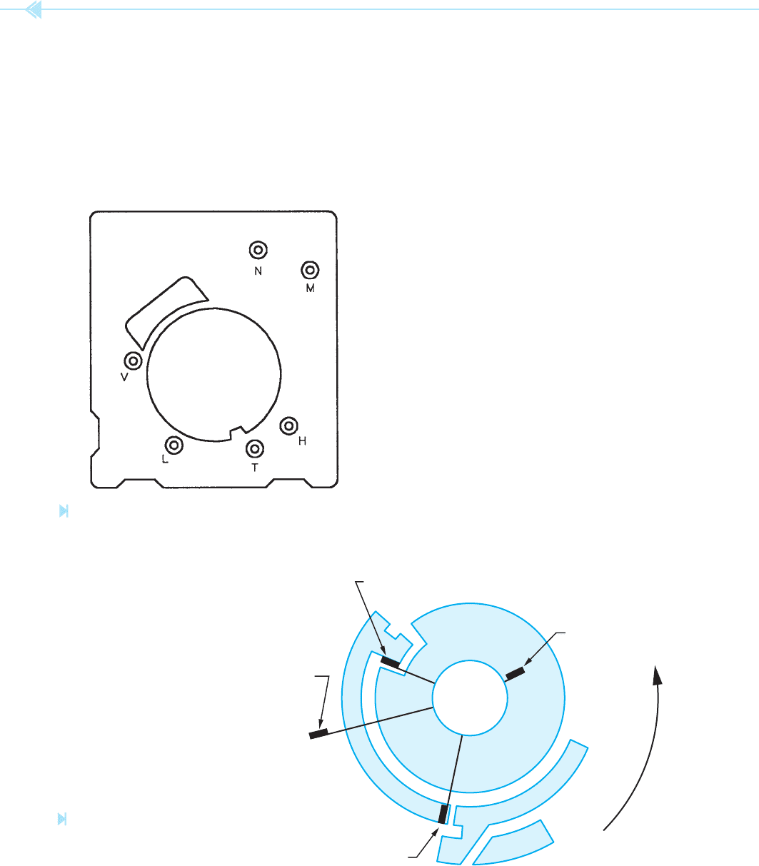
located on the back side of the drive gear.
When the motor turns, it turns these copper
strips also. Contacts ride against these copper
strips and make or break connection to oper-
ate the circuit. A diagram of the copper strips
and contacts is shown in Figure 45–17.
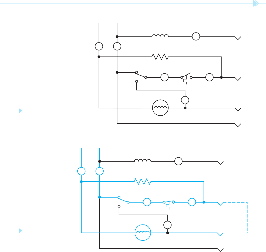
The basic electrical circuit for this unit is shown
in Figure 45–18. Please note that the contact points
A, B, C, and D correspond to the contacts shown
in Figure 45–17. At this point, connection is made
between contacts B and C.
When the thermostat reaches approximately
17°F, its contact will close and produce a current
path to both the motor and heater as shown in
Figure 45–19. The motor begins to turn both the ejec-
tor blades and the copper strips located on the back
of the main gear. At some point, contact between
points B and C is broken and contact between points
C and D is made, as shown in Figure 45–20. The
ejector blades then stall against the ice. A current
path is maintained to the motor between points C
and D and a current path is maintained to the heater
by the closed thermostat contact.
After the surface of the ice has been thawed
by the heater, the ejector blades will begin to
turn again. After the ejector blades have rotated
approximately 180°, the thermostat contact opens,
Figure 45–16
Test points. (Source: Delmar/Cengage Learning)
Figure 45–17
Rotary switch located
on back of drive gear.
(Source: Delmar/Cengage Learning)
CONTACT C (HOLDING SWITCH)
CONTACT D (NEUTRAL)
CONTACT B (THERMOSTAT)
CONTACT A
(WATER VALVE)
• H Heater connection
• T Thermostat connection
• V Water valve connection
6. Probably the greatest difference lies in the
electrical circuit itself. In this model, copper
strips are laminated on an insulated plate
UNIT 45 Household Ice Makers 423
Figure 45–18
Basic schematic diagram for
new model of Whirlpool compact
ice maker. (Source: Delmar/Cengage Learning)
Figure 45–19
A current path is provided
through the heater and
timer motor. (Source: Delmar/
Cengage Learning)
CONTACT
A
V
CONTACT
B
H
T
CONTACT
C
M
CONTACT
D
TIMER MOTOR
4400Ω
72Ω HEATER
WATER VALVE
NL1
SHUTOFF
SWITCH
(UP)
(DN)
THERMOSTAT
NL
CONTACT
A
V
CONTACT
B
H
T
CONTACT
C
M
CONTACT
D
TIMER MOTOR
4400Ω
72Ω HEATER
WATER VALVE
NL1
SHUTOFF
SWITCH
(UP)
(DN)
THERMOSTAT
NL
Figure 45–14. As the blades continue to turn, the
shutoff arm rises and lowers and the copper strips
advance until connection is made between contacts
A and B, Figure 45–21. This provides a current
path through the mold heater to the water solenoid
valve. Because the coil of the solenoid has a much
higher impedance than the mold heater, most of the
line voltage will be dropped across the valve, caus-
ing it to open and re ll the mold. The ejector blades
will continue to turn until they reach the end of the
cycle and the circuit returns to its original condition
as shown in Figure 45–18.
424 SECTION 7 Ice Maker and Refrigeration Controls
CONTACT
A
V
CONTACT
B
H
T
CONTACT
C
M
CONTACT
D
TIMER MOTOR
4400Ω
72Ω HEATER
WATER VALVE
NL1
SHUTOFF
SWITCH
(UP)
(DN)
THERMOSTAT
NL
CONTACT
A
V
CONTACT
B
H
T
CONTACT
C
M
CONTACT
D
TIMER MOTOR
4400Ω
72Ω HEATER
WATER VALVE
NL1
SHUTOFF
SWITCH
(UP)
(DN)
THERMOSTAT
NL
Figure 45–20
The holding contact
maintains the timer motor
circuit. (Source: Delmar/
Cengage Learning)
Figure 45–21
Water valve energizes.
(Source: Delmar/Cengage Learning)
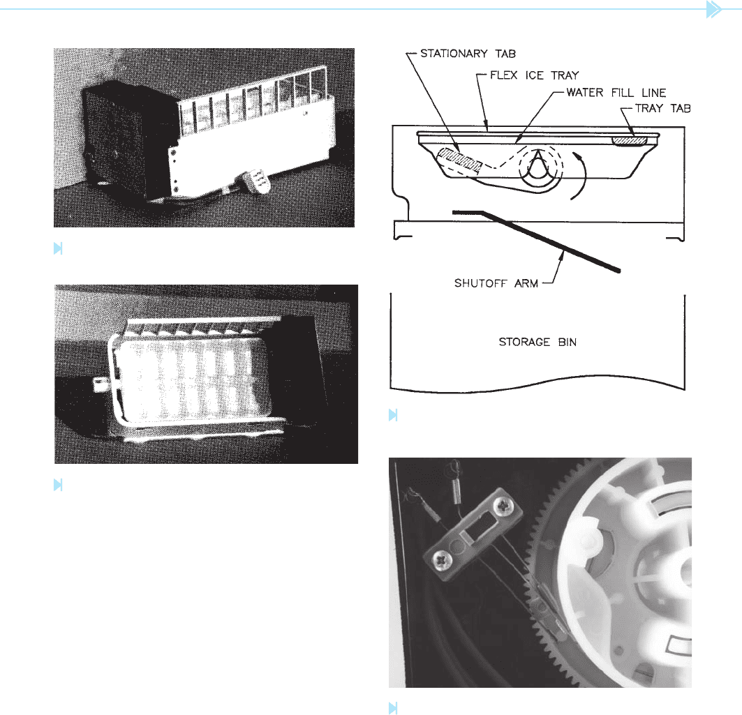
FLEX TRAY ICE MAKERS
Another type of household ice maker is known
as the ex tray, Figures 45–22A and 45–22B.
Although ex tray type ice makers are no longer
manufactured, many are still in service, making it
necessary for technicians in the eld to understand
their operation. Flex tray ice makers differ from the
compact ice makers in several ways. Flex tray ice
makers ll a tray with water and then, after some
UNIT 45 Household Ice Makers 425
Figure 45–22A
Side view of fl ex tray ice maker. (Source: Delmar/Cengage Learning)
Figure 45–23
Flex tray ice maker. (Source: Delmar/Cengage Learning)
Figure 45–24
Water solenoid switch. (Source: Delmar/Cengage Learning)
Figure 45–22B
Top view of fl ex tray ice maker. (Source: Delmar/Cengage Learning)
length of time, turn the tray to dump the cubes
into a storage bin, Figure 45-23. At a point dur-
ing the ejection cycle, a tab located on one side of
the rear of the tray contacts a stationary stop. The
front of the tray continues to turn, causing the tray
to ex or bend at about a 20° angle. This exing
action causes the cubes to dump into the storage
bin. Notice that the time necessary to complete one
cycle is about 13.3 minutes. When the turning tray
approaches the upright position again, a cam oper-
ated switch energizes a water solenoid valve for a
period of about 13 seconds and re lls the tray with
approximately 8 ounces of water, Figure 45–24.
Note that replacement motors for this type of
ice maker operate at a higher rate of speed than
the original motors supplied with the unit. The
new motors cause an ejection cycle to occur every
90 minutes instead of 120 minutes. For this reason,
the water ll switch should be changed with the
motor to prevent short cycling of the ll cycle.
The principle of operation of the ex tray ice
maker is different than that of the compact type.
The ex tray ice maker is incorporated in the same
426 SECTION 7 Ice Maker and Refrigeration Controls
WATER
SOLENOID
VALVE
120
VOLTS
DEFROST
HEATER
DEFROST
THERMOSTAT
EVAPORATOR
FAN
COMPRESSOR
CONDENSER FAN
RUN
START
TIMER
MOTOR
WATER FILL SWITCH
STARTING RELAY
OVERLOAD
CABINET
THERMOSTAT
START CAP.
DEFROST
TIMER
SWITCH
ICEMAKER
Figure 45–25
Schematic of fl ex tray ice maker. (Source: Delmar/Cengage Learning)
circuit with the defrost timer, Figure 45–25. Because
this type of ice maker does not need a mold heater or
separate thermostat, it contains only three electrical
components:
1. A timer motor, which operates both the de-
frost timer and the ice maker, Figure 45–26.
This motor contains a two-stage output
gear. One gear operates the time cycle for
the defrost heater, and the other gear oper-
ates the ice maker. The defrost cycle operates
every 9.6 hours of timer motor running time,
and the ice maker operates every 2 hours of
timer motor running time. When the appli-
ance is in the freeze cycle, the timer motor
can operate only when both the cabinet
thermostat and the defrost heater
thermostat are closed. During the defrost
cycle, however, the timer motor will continue
to operate regardless of the condition of either
thermostat.
2. Defrost timer switch, Figure 45–27.
3. Water ll switch, Figure 45–24.
Another operating difference is that the ex tray
ice maker is more dependent on mechanical control

UNIT 45 Household Ice Makers 427
When the shutoff arm is held up, the pin will
not be released and the tray will not enter into an
ejection cycle. The operation of the ice maker can
be manually stopped by lifting the arm above its
normal turnoff position.
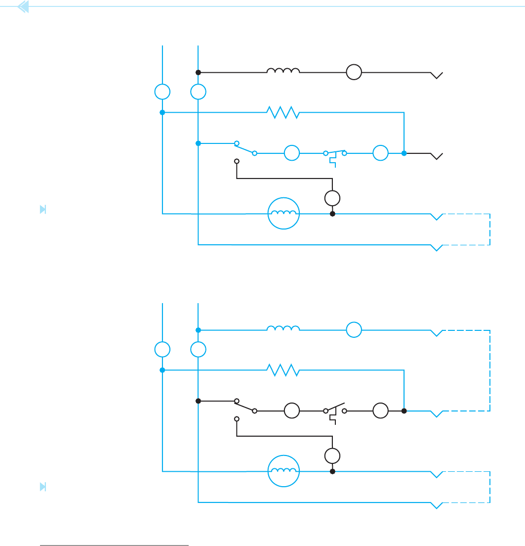
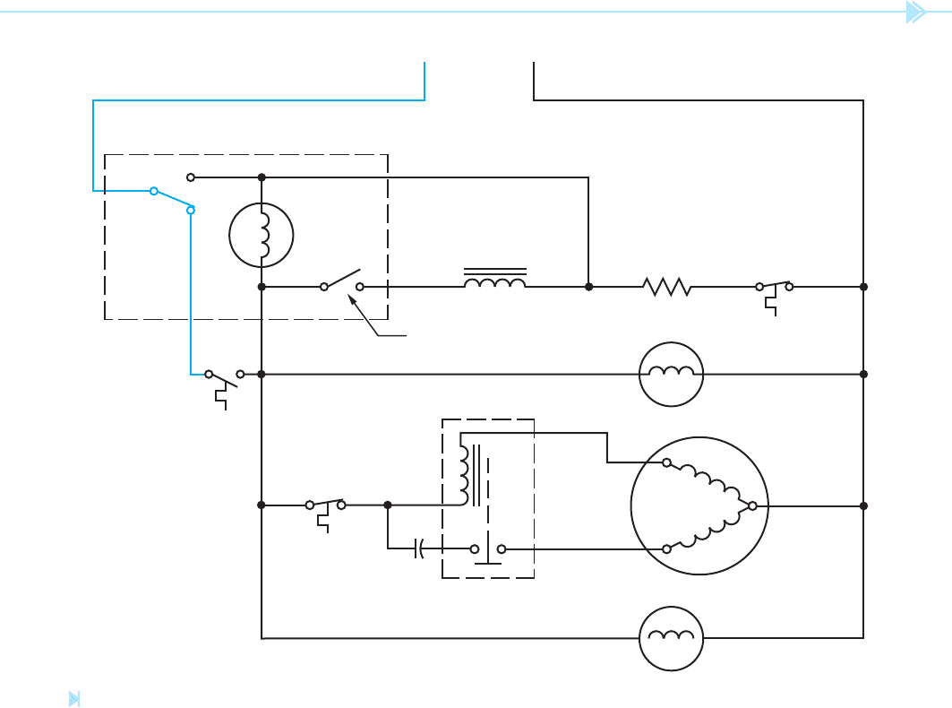
CIRCUIT OPERATION
In the rst stage of operation, the circuit is shown
during the freeze cycle, Figure 45–29. The cabinet
thermostat and defrost heater thermostat are both
closed. At this point, several circuit paths exist.
One circuit is completed through the timer motor,
defrost heater, and defrost thermostat. A circuit is
completed through the evaporator fan, condenser
fan, and the run winding of the compressor. If
the cabinet thermostat should open, as shown in
Figure 45–30, the timer motor also stops.
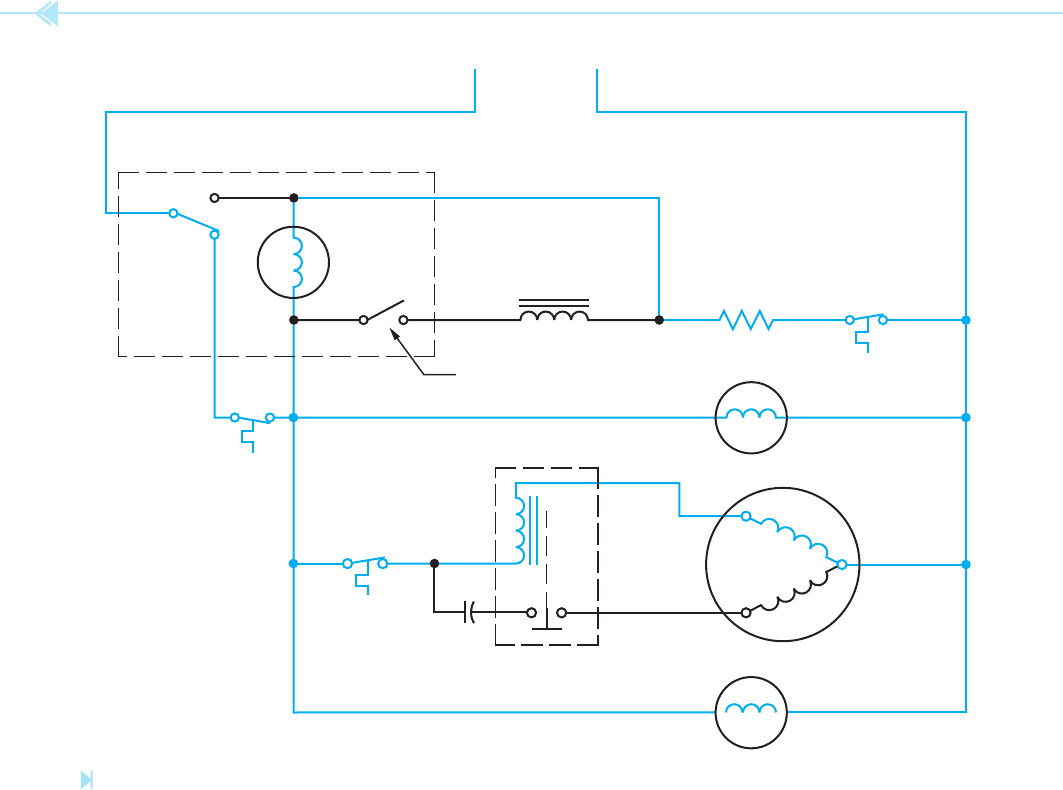
After 9.6 hours of timer motor operation, the
defrost timer switch changes position and completes
the circuits shown in Figure 45–31. The defrost
heater is now connected directly to the power line,
which permits it to warm the evaporator and melt
accumulations of frost. A current path also exists
through the timer motor to the evaporator fan,
compressor run winding, and condenser fan. It is
this circuit path that permits the timer motor to con-
tinue operation if the defrost thermostat should open
its contacts. The timer motor must continue to run,
or the defrost cycle cannot be completed. Note that
Figure 45–26
Timer motor. (Source: Delmar/Cengage Learning)
Figure 45–27
Defrost timer switch. (Source: Delmar/Cengage Learning)
Figure 45–28
Locking pin. (Source: Delmar/Cengage Learning)
than electrical control. The shutoff arm located at
the bottom of the ice maker senses the level of ice
in the storage bin. When this arm is in the down
position, it permits a spring-loaded pin to move for-
ward and lock a gear in place, Figure 45–28. This
locked gear permits the timing motor to turn the
tray through one revolution and eject the ice into
the storage bin. The pin is mechanically reset at the
end of each ejection cycle.
428 SECTION 7 Ice Maker and Refrigeration Controls
WATER
SOLENOID
VALVE
120
VOLTS
DEFROST
HEATER
DEFROST
THERMOSTAT
EVAPORATOR
FAN
COMPRESSOR
CONDENSER FAN
RUN
START
TIMER
MOTOR
WATER FILL SWITCH
STARTING RELAY
OVERLOAD
CABINET
THERMOSTAT
START CAP.
DEFROST
TIMER
SWITCH
ICEMAKER
Figure 45–29
First stage of operation. (Source: Delmar/Cengage Learning)
the winding of the timer motor has a much higher
impedance than the run winding of the compressor.
This permits almost all the voltage to be dropped
across the timer motor and very little to be dropped
across the evaporator fan, compressor run winding,
and condenser fan. At this time, the timer motor will
operate, but the other motors will not. The defrost
cycle lasts for approximately 21.5 minutes.
At the end of the defrost cycle, the defrost timer
switch changes back to its normal position. Because
UNIT 45 Household Ice Makers 429
Figure 45–30
Cabinet thermostat opens. (Source: Delmar/Cengage Learning)
WATER
SOLENOID
VALVE
120
VOLTS
DEFROST
HEATER
DEFROST
THERMOSTAT
EVAPORATOR
FAN
COMPRESSOR
CONDENSER FAN
RUN
START
TIMER
MOTOR
WATER FILL SWITCH
STARTING RELAY
OVERLOAD
CABINET
THERMOSTAT
START CAP.
DEFROST
TIMER
SWITCH
ICEMAKER
the defrost thermostat opens its contacts at approxi-
mately 70°F and does not reclose them until the
evaporator reaches about 2°F, it is normal for these
contacts to be open at the end of the defrost cycle,
Figure 45–32. During this time, the timer motor is
turned off.
Under normal conditions, the ice maker acti-
vates after 2 hours of timer motor running time.
Figure 45–33 shows the condition of the circuit
near the end of the ejection cycle. The cam-operated
water ll switch has closed and now completes a
circuit through the water solenoid valve, defrost