Stephen L. Herman, Bennie Sparkman. Electricity and Controls for HVAC-R (6th edition)
Подождите немного. Документ загружается.


400
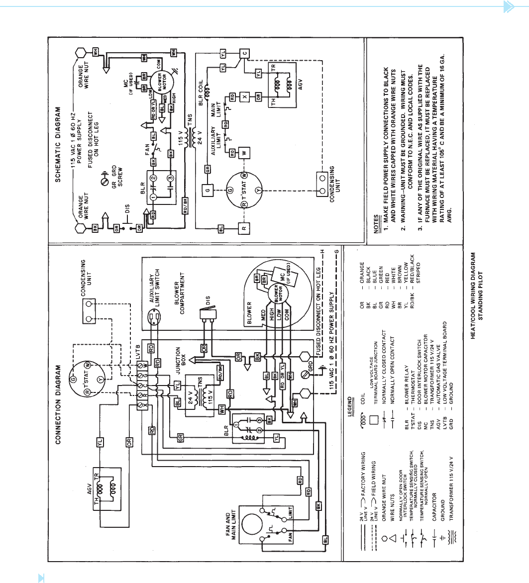
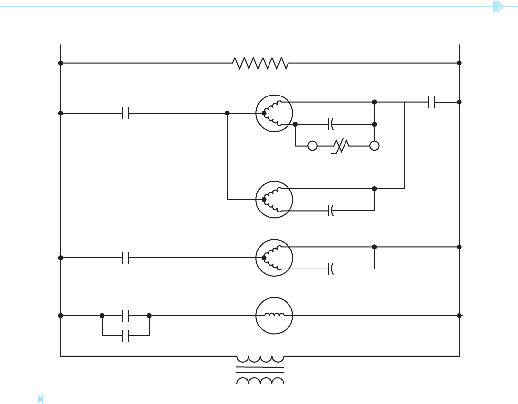
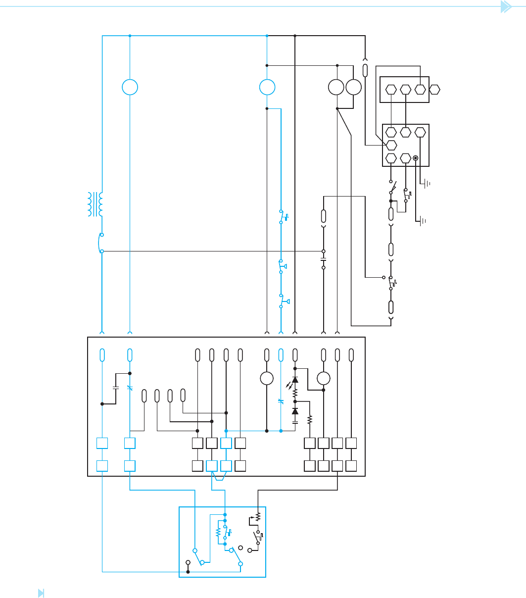
The schematic shown in Figure 44–1 is for a unit
that contains both electric air conditioning and
gas heating in the same package. This drawing
shows both a connection diagram and a schematic
diagram of this unit.
This diagram shows mainly the heating and
blower controls. At the bottom of the schematic dia-
gram is a component labeled
condensing unit.
This is the only reference to the air conditioning
compressor and condenser fan on this schematic.
This is not uncommon for a packaged unit.
THE COOLING CYCLE
The thermostat shows four terminal connections.
The terminal labeled R is connected to one side of the
24-volt control transformer. When the thermostat
is in the cooling position, an increase in temperature
OBJECTIVES
After studying this unit the student should
be able to:
Discuss the operation of an air
conditioning system that operates in
conjunction with a gas heating system
Interpret the schematic diagram for the
air conditioning system
Interpret the schematic diagram for the
heating system
Packaged Units:
Electric Air
Conditioning
and Gas
Heating
UNIT 44
UNIT 44 Packaged Units: Electric Air Conditioning and Gas Heating 401
Figure 44–1
Schematic for an air conditioning and heating package unit. (Source: Delmar/Cengage Learning)
402 SECTION 6 Troubleshooting Using Control Schematics
permits the fan to operate in low speed when the
unit is in the heating cycle, and in high speed when
the unit is in the cooling cycle.
THE DOOR INTERLOCK SWITCH
The door interlock is shown on the schematic
as a normally open push button labeled (DIS). The
function of this switch is to permit the unit to oper-
ate only when the furnace door is closed. When
the door is opened, the 120-volt power supply is
broken to the unit. Most door interlock switches are
so designed that they are actually a two-position
switch. When the door is open, the switch can be
pulled out. This causes the switch to make connec-
tion so the unit can be serviced.
ELECTRONIC CONTROL
OF BLOWER MOTOR AND
COMPRESSOR LOCK-OUT
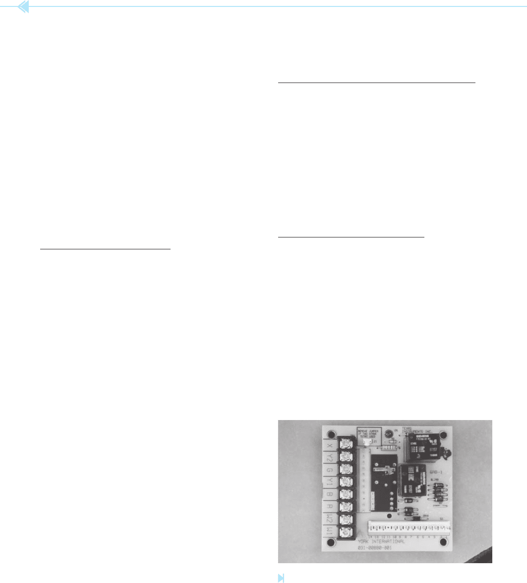
Many units employ electronic control for some
of their functions. Troubleshooting for electronic
circuit boards is generally accomplished by deter-
mining if the board has the proper input informa-
tion to obtain an output. If the inputs and outputs
are correct, the board is good and the problem lies
somewhere else in the circuit. The circuit board
shown in Figure 44–2 is designed to control the
blower for a cooling unit with gas or electric heat.
will cause terminal R to make connection with ter-
minals G and Y. When power is applied to terminal
Y, a circuit is completed to the condensing unit. The
other side of the condensing unit is connected to
terminal C, which completes the circuit back to the
control transformer. This starts the air conditioning
compressor and condenser fan.
Terminal G of the thermostat is connected to the
blower relay coil (BLR). When BLR coil energizes,
both BLR contacts change position. The normally
closed contact opens and prevents the possibility
that power can be applied to the low-speed terminal
of the blower fan motor. The normally open contact
closes and connects power to the high-speed termi-
nal of the motor. Notice that the indoor blower fan
operates in the high-speed position when the air
conditioning unit is started.
THE HEATING CYCLE
When the thermostat is in the heating position, a
decrease of temperature will cause the thermostat to
make connection between terminals R and W. This
permits a circuit to be completed through the automatic
gas valve (AGV). When the AGV is energized, gas is per-
mitted to ow to the main burner where it is ignited by
the pilot light. Two high-limit contacts are connected
in series with the automatic gas valve. One is labeled
auxiliary limit, and the other is labeled main
limit
. The wiring diagram shows the main limit to
be located in the fan-limit switch. The auxiliary limit
switch is in a separate location. Both of these switches
are normally closed and are shown to be temperature
activated. The schematic also shows that an increase
in temperature will cause them to open. Because both
are connected in series with the AGV, the circuit will be
broken to the valve if either one opens.
In the heating cycle, the indoor blower fan is con-
trolled by the fan switch. The fan switch is tempera-
ture activated. After the gas burner has been turned
on, the temperature of the furnace increases. When
the temperature has risen to a high enough level,
the fan switch will close and connect the low-speed
terminal of the blower motor to the power line.
Notice that the fan switch is connected in series with
the normally closed BLR contact. When BLR relay
is deenergized, the fan switch is permitted to control
the operation of the blower fan. The blower fan relay
Figure 44–2
Blower motor and compressor lock-out control board.
(Source: Delmar/Cengage Learning)
UNIT 44 Packaged Units: Electric Air Conditioning and Gas Heating 403
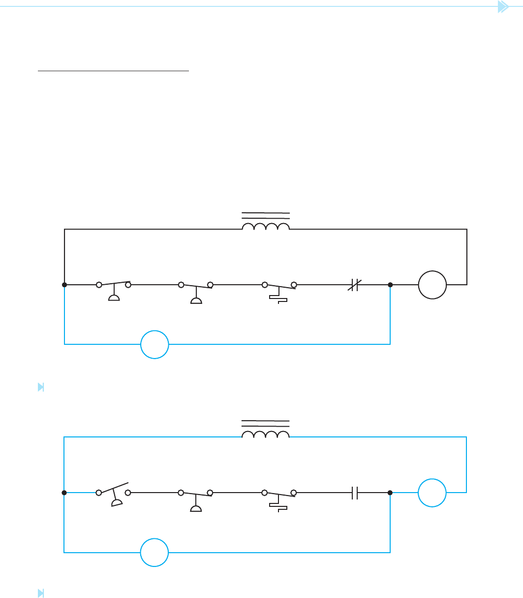
evaporator temperature switch are closed and pro-
vide a complete circuit to the compressor contactor
coil. Because the lock-out relay coil is connected in
parallel with these switches, almost no voltage is
dropped across the LOR coil and it remains turned
off. If one of the switches should open, however,
the lock-out relay coil becomes connected in series
with the compressor contactor coil, Figure 44–4.
Because the impedance of the lock-out relay coil is
much higher than the compressor contactor coil,
almost all the 24 volts is dropped across the LOR
coil and very little voltage is across the CC coil. The
compressor contactor cannot energize because of
the low voltage applied to the coil.
The circuit board also provides lock-out protection
for the compressor.
LOCK-OUT PROTECTION
Lock-out protection involves the use of a high-
impedance relay that becomes connected in series
with the compressor contactor coil in the event of a
problem with the compressor circuit. In the circuit
shown in Figure 44–3, the coil of the lock-out
relay is connected in parallel with the normally
closed safety switches used to help protect the
compressor. Under normal conditions the high-
pressure switch, low-pressure switch, and the low
EVAP- TEMP-
ORATOR ERATURE
HP LP
LOR
24 VAC
LOR
CC
LOCK-OUT RELAY
Figure 44–3
Basic lock-out circuit. (Source: Delmar/Cengage Learning)
Figure 44–4
A circuit exists through the LOR coil and CC coil.
(Source: Delmar/Cengage Learning)
EVAP- TEMP-
ORATOR ERATURE
HP
LP
LOR
24 VAC
LOR
LOCK-OUT RELAY
CC
404 SECTION 6 Troubleshooting Using Control Schematics
OPERATION OF THE COMPRESSOR
LOCK-OUT RELAY
The compressor lock-out relay can operate only
when the thermostat is set in the cooling mode.
In Figure 44–9 it is assumed that the thermostat
has been set for the cooling mode and the ther-
mostat contact is closed. The main current path
is through the normally closed K1 contact, low-
pressure switch, high-pressure switch, and evapora-
tor temperature switch to the coil of 1M contactor.
The current takes this path because of the high
impedance of coil K1. When coil 1M energizes, the
compressor and condenser fan start, Figure 44–5.
There is also a current path through the thermostat
fan switch, the normally closed K3 contact and 2M
coil. When the 2M coil energizes, the evaporator fan
motor starts. The circuit will continue to operate in
this manner until the thermostat contact opens or
some other problem occurs.
Now assume that the low-pressure switch opens,
Figure 44–10. The open circuit caused by the open
low-pressure switch now connects coil K1 in series
with coil 1M. Because coil K1 has a much higher
impedance than 1M, most of the voltage is across
K1 and not 1M, causing the K1 relay to energize
and the 1M contactor to deenergize. The normally
closed K1 contacts open and the normally open
K1 contacts close. When the normally open K1
contacts close, a current path is provided to the
compressor lock-out indicator. The now open K1
contact prevents the compressor from restarting if
the low-pressure switch should reclose. The circuit
will remain in this condition until the control power
is interrupted.
The normally closed LOR contact connected in
series with the compressor contactor coil opens.
If the high-pressure switch should close, the now
open LOR contact prevents the compressor contac-
tor from energizing. The circuit will remain in this
condition until the control power is turned off and
the lock-out relay coil deenergizes. The line volt-
age connections for the blower control and lock-
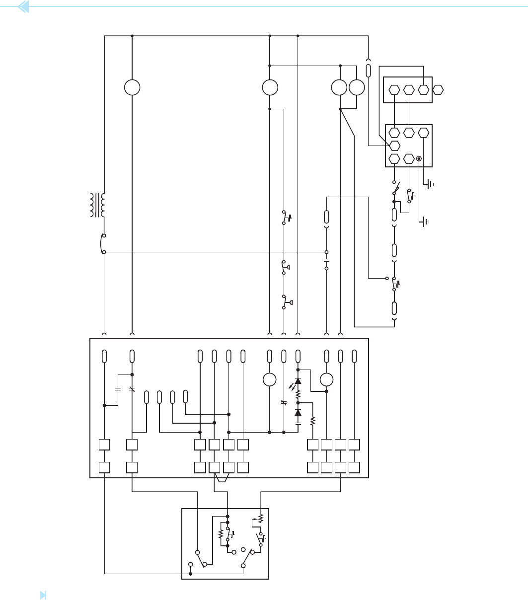
out relay circuit board are shown in Figure 44–5.
The circuit board and basic controls are shown in
Figure 44–6.
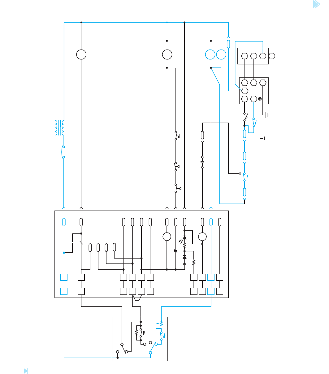
CIRCUIT OPERATION
When the heating thermostat contact closes, a cir-
cuit exists to the time delay relay (TDR) and draft
motor relay (DMR), Figure 44–7. Power is also
supplied to the ignition control module. The draft
motor controls the centrifugal switch connected to
the thermostat input of the ignition control module.
Its function is used to insure that gas will not be
supplied to the burner unless the draft motor is in
operation.
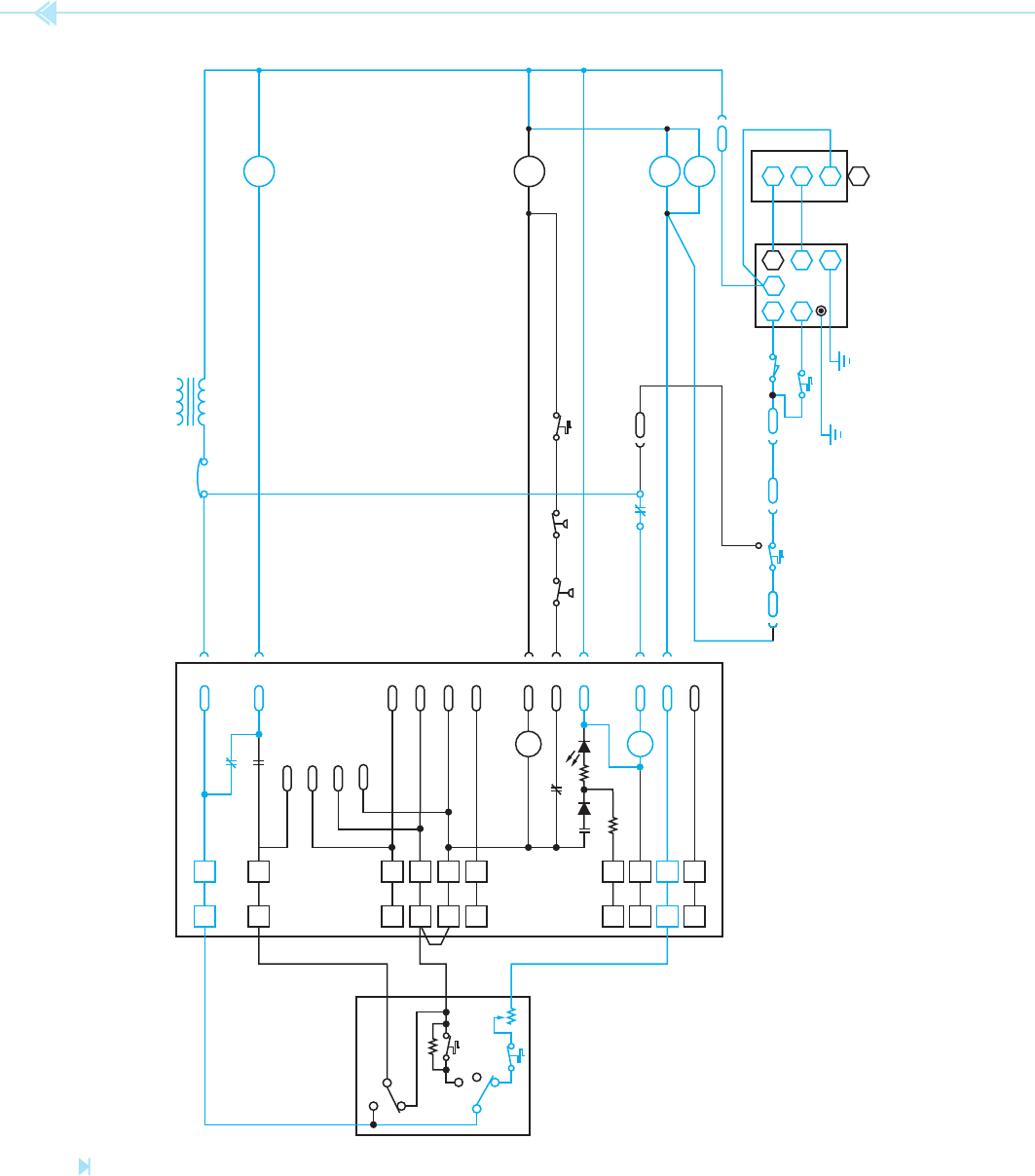
In Figure 44–8, it is assumed that the centrifugal
switch has closed and permitted the gas burner to
ignite. It is also assumed that the time delay relay
has permitted TDR contacts to close. When the
TDR contacts close, a current path is provided to
the coil of the K3 relay causing all K3 contacts to
change position. When the normally open K3 con-
tact closes, a current path is provided to the coil of
the 2M contactor. When 2M energizes, the blower
motor turns on, Figure 44–5. The circuit will con-
tinue to operate in this manner until the thermostat
contacts reopen.
UNIT 44 Packaged Units: Electric Air Conditioning and Gas Heating 405
Figure 44–5
Line voltage circuit. (Source: Delmar/Cengage Learning)
L2L1
TDR
DMR
CONTROL TRANSFORMER
DRAFT MOTOR (GAS ONLY)
2M
EVAPORATOR FAN
1M
1M COMPRESSOR CONTACTOR
2M EVAPORATOR FAN CONTACTOR
DMR DRAFT MOTOR FAN RELAY
TDR TIME DELAY RELAY
COMPRESSOR
CRANK CASE HEATER
CONDENSER FAN
HARD START KIT
1M
B
A
406 SECTION 6 Troubleshooting Using Control Schematics
2M
1M
TDR
DMR
TEHPLP
S4TDR
S4
S4
P4
S3
LS1
CS
LS2
TH PV
GND
R1
MV
IC
4
TH/R
TH
TR
GNC
GV
SENSOR
SPARK
1M COMPRESSOR CONTACTOR
2M EVAPORATOR FAN CONTACTOR
CB CIRCUIT BREAKER
CLI COMPRESSOR LOCK-OUT INDICATOR
CS CENTRIFUGAL SWITCH
DMR DRAFT MOTOR RELAY
GV GAS VALVE
HP HIGH-PRESSURE CONTROL
IC IGNITION CONTROL
K1 COMPRESSOR LOCK-OUT RELAY
K3 BLOWER INTERLOCK RELAY
LP LOW-PRESSURE CONTROL
LS1 LIMIT SWITCH
LS2 LIMIT SWITCH
TE LOW EVAP. TEMP. THERMOSTAT
TH THERMOSTAT, H E ATING
TDR TIME DELAY RELAY
CB
S1
K3
B
7
X 11
5
S1
W1
2
13
S1
W2 5
10
S1
Y2 10
3
S1
Z 1
14
S1
N 4
12
S1
Y1 8
4
S1
K1
1
S1
2
S1
7
S1
6
S1
R 6
9
S6
S8
S8
S8
K1 CL1
K1
K3
K3
FAN ON
FAN AUTO
OFF
THERMOSTAT
COOL
HEAT
G 9
Figure 44–6
Control circuit for a cooling unit and gas heat. (Source: Delmar/Cengage Learning)
UNIT 44 Packaged Units: Electric Air Conditioning and Gas Heating 407
2M
1M
TDR
DMR
TEHPLP
S4TDR
S4S4 P4 S3
LS1
CS
LS2
TH PV
GND
R1
MV
IC
4
TH/R
TH
TR
GNC
GV
SENSOR
SPARK
1M COMPRESSOR CONTACTOR
2M EVAPORATOR FAN CONTACTOR
CB CIRCUIT BREAKER
CLI COMPRESSOR LOCK-OUT INDICATOR
CS CENTRIFUGAL SWITCH
DMR DRAFT MOTOR RELAY
GV GAS VALVE
HP HIGH-PRESSURE CONTROL
IC IGNITION CONTROL
K1 COMPRESSOR LOCK-OUT RELAY
K3 BLOWER INTERLOCK RELAY
LP LOW-PRESSURE CONTROL
LS1 LIMIT SWITCH
LS2 LIMIT SWITCH
TE LOW EVAP. TEMP. THERMOSTAT
TH THERMOSTAT, H E ATING
TDR TIME DELAY RELAY
CB
S1
K3B 7
X 11
5
S1
W1 2
13
S1
W2 5
10
S1
Y2
10
3
S1
Z 1
14
S1
N 4
12
S1
Y1 8
4
S1
K1
1
S1
2
S1
7
S1
6
S1
R 6
9
S6
S8
S8
S8
K1 CL1
K1
K3
K3
FAN ON
FAN AUTO
OFF
THERMOSTAT
COOL
HEAT
G
9
Figure 44–7
The heating thermostat contact closes. (Source: Delmar/Cengage Learning)
408 SECTION 6 Troubleshooting Using Control Schematics
Figure 44–8
The blower motor turns on after a time delay. (Source: Delmar/Cengage Learning)
2M
1M
TDR
DMR
TEHPLP
S4TDR
S4S4 P4 S3
LS1
CS
LS2
TH PV
GND
R1
MV
IC
4
TH/R
TH
TR
GNC
GV
SENSOR
SPARK
1M COMPRESSOR CONTACTOR
2M EVAPORATOR FAN CONTACTOR
CB CIRCUIT BREAKER
CLI COMPRESSOR LOCK-OUT INDICATOR
CS CENTRIFUGAL SWITCH
DMR DRAFT MOTOR RELAY
GV GAS VALVE
HP HIGH-PRESSURE CONTROL
IC IGNITION CONTROL
K1 COMPRESSOR LOCK-OUT RELAY
K3 BLOWER INTERLOCK RELAY
LP LOW-PRESSURE CONTROL
LS1 LIMIT SWITCH
LS2 LIMIT SWITCH
TE LOW EVAP. TEMP. THERMOSTAT
TH THERMOSTAT, H E ATING
TDR TIME DELAY RELAY
CB
S1
K3B 7
X 11
5
S1
W1
2
13
S1
W2 5
10
S1
Y2 10
3
S1
Z 1
14
S1
N 4
12
S1
Y1 8
4
S1
K1
1
S1
2
S1
7
S1
6
S1
R 6
9
S6
S8
S8
S8
K1 CL1
K1
K3
K3
FAN ON
FAN AUTO
OFF
THERMOSTAT
COOL
HEAT
G 9
UNIT 44 Packaged Units: Electric Air Conditioning and Gas Heating 409
Figure 44–9
Circuit during normal cooling cycle. (Source: Delmar/Cengage Learning)
2M
1M
TDR
DMR
TEHPLP
S4TDR
S4S4 P4 S3
LS1
CS
LS2
TH PV
GND
R1
MV
IC
4
TH/R
TH
TR
GNC
GV
SENSOR
SPARK
1M COMPRESSOR CONTACTOR
2M EVAPORATOR FAN CONTACTOR
CB CIRCUIT BREAKER
CLI COMPRESSOR LOCK-OUT INDICATOR
CS CENTRIFUGAL SWITCH
DMR DRAFT MOTOR RELAY
GV GAS VALVE
HP HIGH-PRESSURE CONTROL
IC IGNITION CONTROL
K1 COMPRESSOR LOCK-OUT RELAY
K3 BLOWER INTERLOCK RELAY
LP LOW-PRESSURE CONTROL
LS1 LIMIT SWITCH
LS2 LIMIT SWITCH
TE LOW EVAP. TEMP. THERMOSTAT
TH THERMOSTAT, H E ATING
TDR TIME DELAY RELAY
CB
S1
K3B 7
X 11
5
S1
W1 2
13
S1
W2 5
10
S1
Y2
10
3
S1
Z 1
14
S1
N
4
12
S1
Y1 8
4
S1
K1
1
S1
2
S1
7
S1
6
S1
R 6
9
S6
S8
S8
S8
K1 CL1
K1
K3
K3
FAN ON
FAN AUTO
OFF
THERMOSTAT
COOL
HEAT
G 9