Stephen L. Herman, Bennie Sparkman. Electricity and Controls for HVAC-R (6th edition)
Подождите немного. Документ загружается.


500 SECTION 8 Solid-State Devices
SUMMARY
The unijunction transistor has two bases and one emitter.
The unijunction transistor is a member of the thyristor family of components.
Injunction transistors have two states of operation: on or off.
The unijunction transistor operates like a snap action, voltage sensitive switch.
KEY TERMS
thyristors
unijunction transistor
REVIEW QUESTIONS
1. What do the letters UJT stand for?
2. How many layers of semiconductor material are used to construct a UJT?
3. Brie y explain the operation of the UJT.
4. Draw the schematic symbol for the UJT.
5. Brie y explain how to test a UJT with an ohmmeter.

501
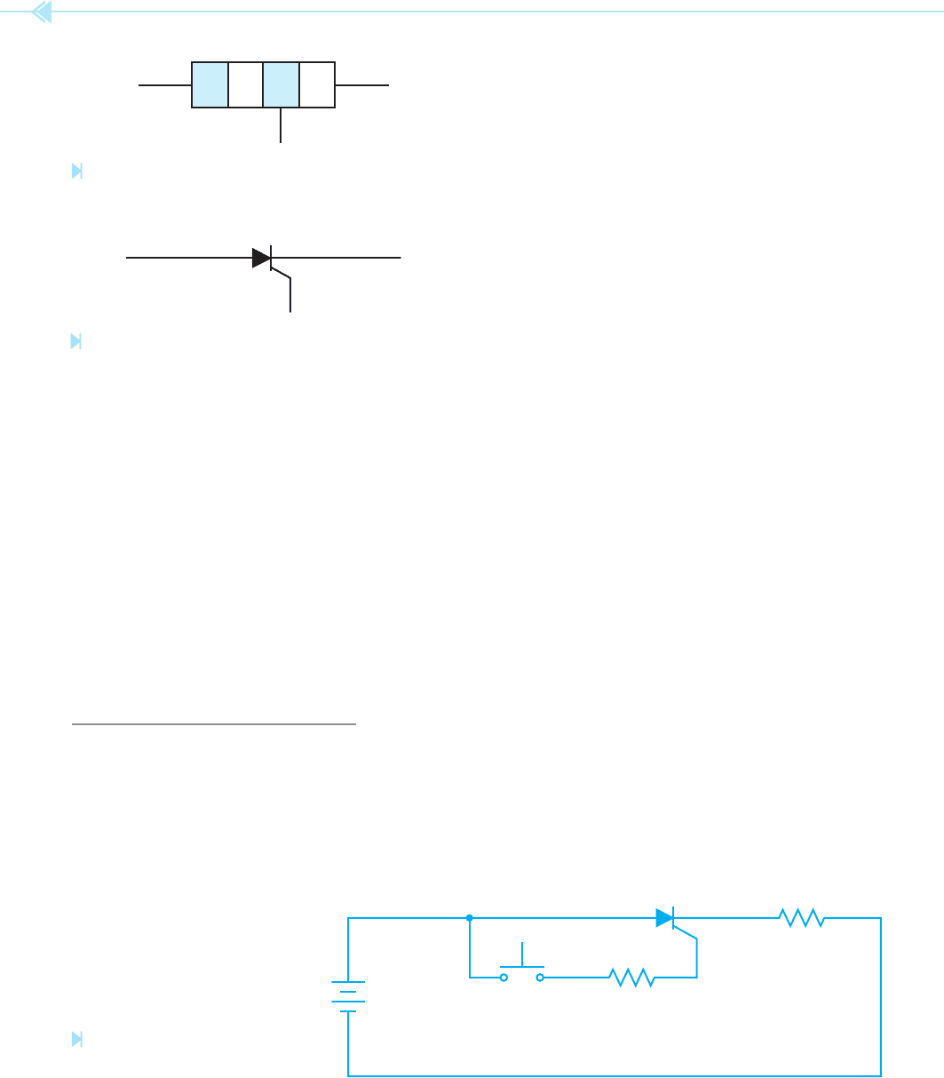
The silicon-controlled recti er (SCR) is
often referred to as the PNPN junction because it is
made by joining four layers of semiconductor mate-
rial together, Figure 54–1. The schematic symbol
for the SCR is shown in Figure 54–2. Notice that the
symbol for the SCR is the same as the diode except
that a gate lead has been added.
SCR CHARACTERISTICS
The SCR is a member of a family of devices known
as thyristors. Thyristors are digital devices in that
they have only two states, on or off. The SCR is
used when it is necessary for an electronic device
to control a large amount of power. Assume an
SCR has been connected in a circuit as shown in
Figure 54–3. When the SCR is turned off, it will
drop the full voltage of the circuit and 200 volts will
UNIT 54
The Silicon-
Controlled
Rectifi er
OBJECTIVES
After studying this unit the student should
be able to:
Discuss the operation of a silicon-
controlled rectifi er (SCR) in a DC
circuit and an AC circuit
Draw the schematic symbol for an SCR
Discuss phase shifting
Test an SCR with an ohmmeter
Connect an SCR in a circuit
502 SECTION 8 Solid-State Devices
connected to the same polarity as the anode if it is
to turn the anode-cathode section of the SCR on.
Once the gate has turned the SCR on, it will remain
turned on until the current owing through the
anode-cathode drops to a low enough level to per-
mit the device to turn off. The amount of current
required to keep the SCR turned on is called the
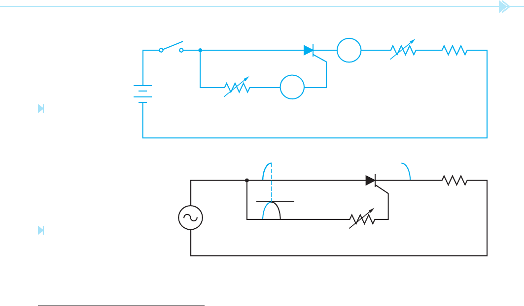
holding current, Figure 54–4. Assume resis-
tor R1 has been adjusted for its highest value and
resistor R2 has been adjusted to its lowest or 0
value. When switch S1 is closed, no current will
ow through the anode-cathode section of the
SCR because resistor R1 prevents enough current
owing through the gate-cathode section of the
SCR to trigger the device. If resistor R1 is slowly
decreased in value, current ow through the gate-
cathode will slowly increase. When the gate cur-
rent reaches a certain level, assume 5 mA for this
SCR, the SCR will re or turn on. When the SCR
res, current will ow through the anode-cathode
section and the voltage drop across the device
becomes about 1 volt. Once the SCR has turned
on, the gate has no more control over the device
and could be disconnected from the anode without
having any effect on the circuit. When the SCR
res, the anode-cathode becomes a short circuit for
all practical purposes and current ow is limited by
resistor R3. Now assume that resistor R2 is slowly
increased in value. When the resistance of R2 is
slowly increased, the current ow through the
anode-cathode will slowly decrease. Assume that
when the current ow through the anode-cathode
drops to 100 mA, the device suddenly turns off
and the current ow drops to 0. This SCR requires
5 mA of gate current to turn it on, and has a hold-
ing current value of 100 mA.
appear across the anode and cathode. Although
the SCR has a voltage drop of 200 volts, there is no
current ow in the circuit. The SCR does not have
to dissipate any power in this condition (200 volts ⫻
0 amps ⫽ 0 watts). When the push button is pressed,
the SCR will turn on. When the SCR turns on, it will
have a voltage drop across its anode and cathode
of about 1 volt. The load resistor limits the circuit
current to 2 amps (200 volts/100 ohms ⫽ 2 amps).
Because the SCR now has a voltage drop of 1 volt
and 2 amps of current is owing through it, it must
now dissipate 2 watts of heat (1 volt ⫻ 2 amps ⫽
2 watts). Notice that the SCR is dissipating only
2 watts of power, but is controlling 200 watts.
THE SCR IN A DC CIRCUIT
When an SCR is connected in a DC circuit as shown
in Figure 54–3, the gate will turn the SCR on
but will not turn the SCR off. The gate must be
PN NP
Figure 54–1
PNPN junction. (Source: Delmar/Cengage Learning)
ANODE+–CATHODE
GATE
Figure 54–2
Schematic symbol of an SCR. (Source: Delmar/Cengage Learning)
200 VOLTS DC
LOAD 100 OHMS
Figure 54–3
Gate turns SCR on. (Source: Delmar/
Cengage Learning)
UNIT 54 The Silicon-Controlled Rectifi er 503
THE SCR IN AN AC CIRCUIT
The SCR is a recti er. When it is connected in an
AC circuit the output will be DC. The SCR operates
in the same manner in an AC circuit as it does in a
DC circuit. The difference in operation is caused by
the AC waveform falling back to 0 at the end of each
half cycle. When the AC waveform drops to 0 at the
end of each half cycle, it will permit the SCR to turn
off. This means the gate must re-trigger the SCR for
each cycle it is to conduct. Refer to the circuit shown
in Figure 54–5.
Assume that the variable resistor connected to
the gate has been adjusted to permit 5 mA of cur-
rent to ow when the voltage applied to the anode
reaches its peak value. When the SCR turns on,
current will begin owing through the load resis-
tor when the AC waveform is at its positive peak.
Current will continue to ow through the load until
the decreasing voltage of the sine wave causes the
current to drop below the holding current level of
100 mA. When the current through the anode-
cathode drops below 100 mA, the SCR turns off and
all current ow stops. The SCR will remain turned
off when the AC waveform goes into the negative
half cycle because it is reverse biased and cannot
be red.
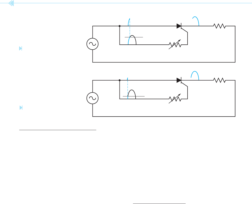
If the resistance connected in series with the
gate is reduced, a current of 5 mA will be reached
before the AC waveform reaches it peak value,
Figure 54–6. This causes the SCR to re sooner in
the cycle. Since the SCR res sooner, current is per-
mitted to ow through the load resistor for a longer
period of time, which causes a higher average volt-
age drop across the load. If the resistance of the gate
circuit is reduced again, as shown in Figure 54–7,
the 5 mA of gate current needed to re the SCR will
be reached sooner than before. This permits cur-
rent to begin owing through the load sooner than
before, which permits a higher average voltage to be
dropped across the load.
Notice that this circuit will permit the SCR to con-
trol only half of the positive waveform. The latest the
SCR can be red in the cycle is when the AC wave-
form is at 90° or peak. If a lamp were used as the
load for this circuit, it would burn at half brightness
when the SCR rst turned on. This control would
permit the lamp to be operated from half brightness
to full brightness, but it could not be operated at a
level less than half brightness.
R1
S1
R2 R3
A2
A1
Figure 54–4
Operation of an SCR
in a DC circuit. (Source:
Delmar/Cengage Learning)
5 mA
LOAD
Figure 54–5
SCR fi res when the AC waveform
reaches peak value. (Source: Delmar/
Cengage Learning)
504 SECTION 8 Solid-State Devices
PHASE SHIFTING THE SCR
If the SCR is to control all of the positive waveform,
it must be phase shifted. As the term implies,
phase shifting means to shift the phase of one thing
in reference to another. In this instance, the volt-
age applied to the gate must be shifted out of phase
with the voltage applied to the anode. There are
several methods that can be used for phase shift-
ing an SCR, but it is beyond the scope of this text
to cover all of them. The basic principles are the
same for all of the methods, however, so only one
method will be covered.
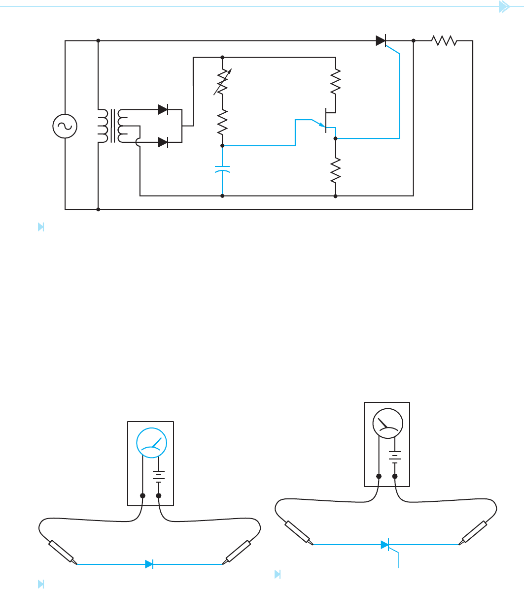
If the SCR is to be phase shifted, the gate circuit
must be unlocked or separated from the anode cir-
cuit. The circuit shown in Figure 54–8 will accom-
plish this. A 24-volt center-tapped transformer has
been used to isolate the gate circuit from the anode
circuit. Diodes D1 and D2 are used to form a two-
diode type of full wave recti er to operate the uni-
junction transistor (UJT) circuit. Resistor R1 is used
to determine the pulse rate of the UJT by controlling
the charge time of capacitor C1. Resistor R2 is used
to limit the current through the emitter of the UJT if
resistor R1 is adjusted to 0 ohms. Resistor R3 limits
current through the base 1–base 2 section when the
UJT turns on. Resistor R4 permits a voltage spike or
pulse to be produced across it when the UJT turns on
and discharges capacitor C1. The pulse produced by
the discharge of capacitor C1 is used to trigger the
gate of the SCR.
Because the pulse of the UJT is used to provide a
trigger for the gate of the SCR, the SCR can now be
red at any time regardless of the voltage applied
to the anode. This means the SCR can now be red
as early or late during the positive half cycle as
desired, because the gate pulse is now determined
by the charge rate of capacitor C1. The voltage
across the load can now be adjusted from 0 to the
full applied voltage.
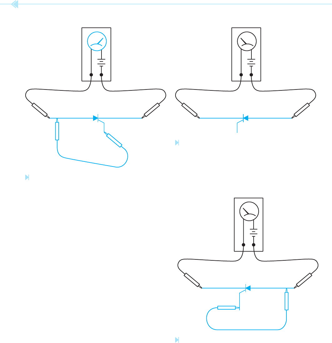
TESTING THE SCR
The SCR can be tested with an ohmmeter. To test
the SCR, connect the positive output lead of the
ohmmeter to the anode and the negative lead to
the cathode. The ohmmeter should indicate no
continuity. Touch the gate of the SCR to the anode.
The ohmmeter should indicate continuity through
the SCR. When the gate lead is removed from the
anode, conduction may stop or continue, depend-
ing on whether the ohmmeter is supplying enough
current to keep the device above its holding current
level or not. If the ohmmeter indicates continuity
through the SCR before the gate is touched to the
anode, the SCR is shorted. If the ohmmeter will not
5 mA
LOAD
5 mA
LOAD
Figure 54–6
SCR fi res before the AC wave-
form reaches peak value.
(Source: Delmar/Cengage Learning)
Figure 54–7
SCR fi res sooner than before.
(Source: Delmar/Cengage Learning)
UNIT 54 The Silicon-Controlled Rectifi er 505
indicate continuity through the SCR after the gate
has been touched to the anode, the SCR is open. The
following step-by-step procedure can be used for
testing an SCR.
1. Using a junction diode, determine which
ohmmeter lead is positive and which is nega-
tive. The ohmmeter will indicate continuity
only when the positive lead is connected to
the anode of the diode and the negative lead
is connected to the cathode, Figure 54–9.
LOAD
R1
50 KILOHMS
R2
100 OHMS
C1
1 µF
24 VOLTS
CENTER TAPPED
R3
330 OHMS
R4
3.3 KILOHMS
UJT
D1
D2
Figure 54–8
UJT phase shift for an SCR. (Source: Delmar/Cengage Learning)
ANODE CATHODE
OHMMETER
+–
Figure 54–9
Determining ohmmeter polarity. (Source: Delmar/Cengage Learning)
2. Connect the positive ohmmeter lead to the
anode of the SCR and the negative lead to the
cathode. The ohmmeter should indicate no
continuity, Figure 54–10.
3. Using a jumper lead, connect the gate of the
SCR to the anode. The ohmmeter should
indicate a forward diode junction when the
connection is made, Figure 54–11.
ANODE CATHODE
GATE
OHMMETER
+–
Figure 54–10
There should be no continuity between anode and
cathode. (Source: Delmar/Cengage Learning)
506 SECTION 8 Solid-State Devices
NOTE: If the jumper is removed, the SCR may
continue to conduct or it may turn off. This will be
determined by whether or not the ohmmeter can
supply enough current to keep the SCR above its
holding current level.
4. Reconnect the SCR so that the cathode is
connected to the positive ohmmeter lead and
the anode is connected to the negative lead.
The ohmmeter should indicate no continuity,
Figure 54–12.
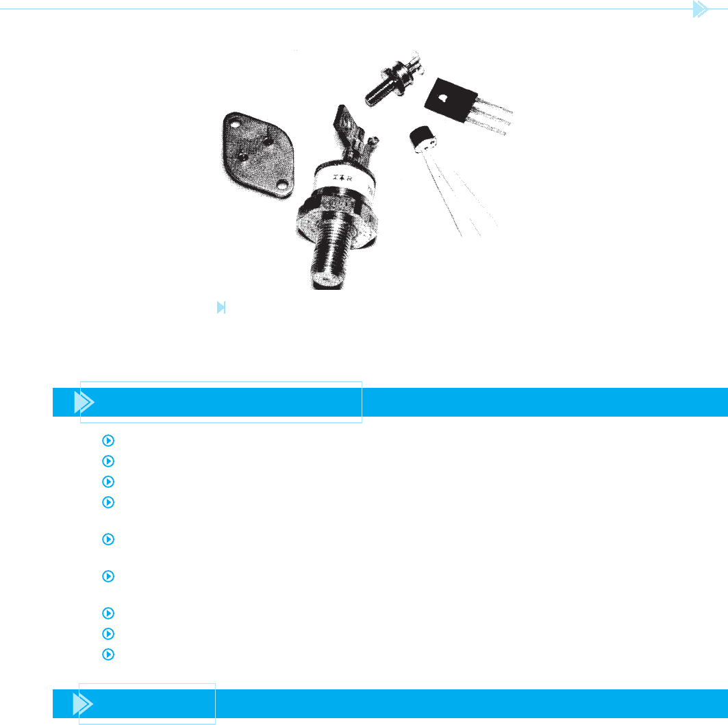
5. If a jumper lead is used to connect the gate to
the anode, the ohmmeter should indicate no
continuity, Figure 54–13. SCRs in different
case styles are shown in Figure 54–14.
NOTE: SCRs designed to switch large current
(50 amperes or more) may indicate some leakage
current with this test. This is normal for some
devices.
ANODE CATHODE
GATE
OHMMETER
+
–
Figure 54–11
Shorting the gate and anode causes the SCR to conduct.
(Source: Delmar/Cengage Learning)
ANODECATHODE
GATE
OHMMETER
+–
Figure 54–12
Reversing the polarity. (Source: Delmar/Cengage Learning)
ANODECATHODE
GATE
OHMMETER
+
–
Figure 54–13
The SCR will not conduct when the polarity is reversed.
(Source: Delmar/Cengage Learning)
UNIT 54 The Silicon-Controlled Rectifi er 507
Figure 54–14
SCRs shown in different case styles. (Source: Delmar/Cengage
Learning)
SUMMARY
The silicon-controlled recti er (SCR) is often referred to as a PNPN junction.
The SCR is a member of the thyristor family of electronic devices.
The SCR has two states of operation: on or off.
When the SCR is connected in a DC circuit, the gate current controls the turn on, but once
the SCR is turned on, the gate cannot turn it off.
Before an SCR can be turned off, the current ow through the anode-cathode section must
drop below the holding current level.
When an SCR is connected in an AC circuit, the voltage returning to zero each half cycle
turns the SCR off.
The SCR is a recti er; it will change alternating current into direct current.
In order to gain complete control of the output waveform, the SCR must be phase shifted.
The unijunction transistor is often used to phase shift an SCR.
KEY TERMS
gate
holding current
phase shifted
PNPN
silicon-controlled
recti er (SCR)

508 SECTION 8 Solid-State Devices
1. What do the letters SCR stand for?
2. How many layers of semiconductor material are joined to form an SCR?
3. SCRs are a member of what family of devices?
4. If an SCR is connected in an AC circuit, is the output AC or DC?
5. Is gate current used to turn the SCR on or off?
6. The amount of current ow through the anode-cathode section needed to keep an
SCR turned on is called what?
7. When an SCR is connected in an AC circuit, what must be done to gain complete
control of the output waveform?
8. What electronic component is generally used to phase shift an SCR?
REVIEW QUESTIONS

509
The diac is a special-purpose bidirectional
diode. The primary function of the diac is to phase
shift a triac. The operation of the diac is very similar
to that of a unijunction transistor, except the diac
is a “bi” or two-directional device. The diac has the
ability to operate in an AC circuit while the UJT is a
DC device only.
There are two schematic symbols for the diac,
Figure 55–1. Either of these symbols is used in an
electronic schematic to illustrate the use of a diac;
therefore, you should become familiar with both.
DIAC CHARACTERISTICS
The diac is a voltage-sensitive switch that can oper-
ate on either polarity, Figure 55–2. When voltage is
applied to the diac, it will remain in the turned-off
state until the applied voltage reaches a predetermined
UNIT 55
The Diac
OBJECTIVES
After studying this unit the student should
be able to:
Draw the schematic symbol for a diac
Discuss the operation of a diac
Connect a diac in a circuit