Stephen L. Herman, Bennie Sparkman. Electricity and Controls for HVAC-R (6th edition)
Подождите немного. Документ загружается.

480 SECTION 8 Solid-State Devices
RECTIFIERS
Diodes can be used to perform many jobs, but their
most common use in industry is to construct a rec-
ti er. A recti er is a device that changes or converts
AC voltage into DC voltage. The simplest type of rec-
ti er is known as the half-wave recti er. Refer
to the circuit shown in Figure 50–5. The half-wave
recti er can be constructed with only one diode, and
gets its name from the fact that it will rectify only half
of the AC waveform applied to it. When the voltage
applied to the anode is positive, the diode is forward
biased and current can ow through the diode, load
resistor, and back to the power supply. When the
voltage applied to the anode becomes negative, the
diode is reverse biased and no current will ow. Since
the diode permits current to ow through the load in
only one direction, the current is DC.
Diodes can be connected to produce full-wave
recti cation, which means both halves of the AC
waveform will be made to ow in the same direc-
tion. One type of full-wave recti er is known as
the bridge recti er and is shown in Figure 50–6.
Notice the bridge recti er requires 4 diodes for
construction.
To understand the operation of the bridge recti er,
assume that point X of the AC source is positive and
point Y is negative. Current will ow to point A of the
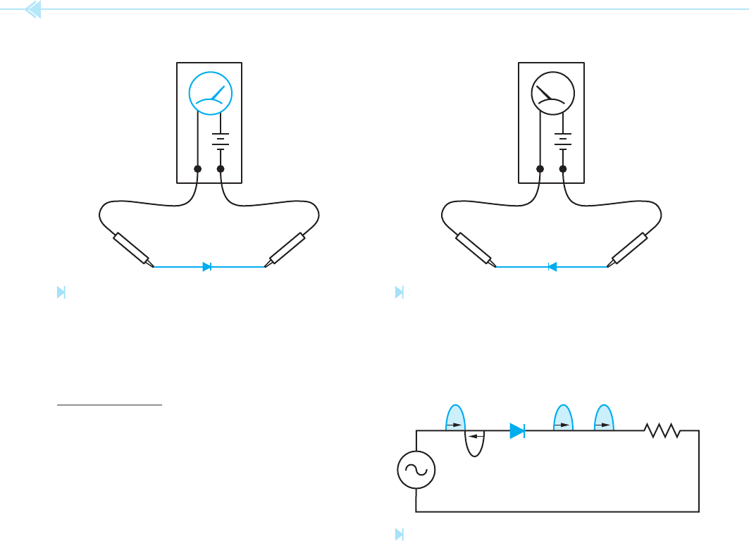
OHMMETER
+–
Figure 50–3
Testing a diode. (Source: Delmar/Cengage Learning)
Figure 50–4
A diode connected in the reverse direction.
(Source: Delmar/Cengage Learning)
OHMMETER
+–
Figure 50–5
Half-wave rectifi er. (Source: Delmar/Cengage Learning)
LOAD
recti er. At point A, diode D4 is reverse biased and
D1 is forward biased. The current will ow through
diode D1 to point B of the recti er. At point B,
diode D2 is reverse biased, so the current must ow
through the load resistor to ground. The current
returns through ground to point D of the recti er. At
point D, both diodes D4 and D3 are forward biased,
but current will not ow from positive to positive.
Therefore, the current will ow through diode D3 to
point C of the bridge, and then to point Y of the AC
source, which is negative at this time. Since current
owed through the load resistor during this half
cycle, a voltage is developed across the resistor.
Now assume that point Y of the AC source is
positive and X is negative. Current will ow from
point Y to point C of the recti er. At point C, diode
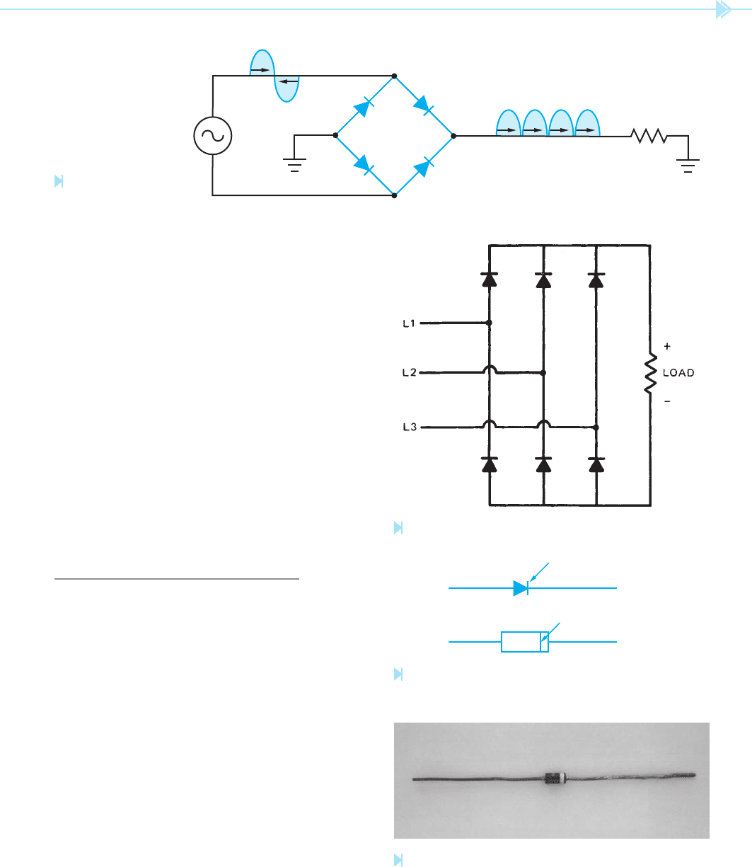
UNIT 50 The PN Junction 481
Figure 50–7
Three-phase bridge rectifi er. (Source: Delmar/Cengage Learning)
Figure 50–8
Lead identifi cation of a plastic case diode.
(Source: Delmar/
Cengage Learning)
Figure 50–9
Junction diode.
(Source: Delmar/Cengage Learning)
Figure 50–6
Bridge rectifi er. (Source:
Delmar/Cengage Learning)
DB
X
Y
D4
D3
C
D2
D1
A
D3 is reverse biased and diode D2 is forward biased.
The current will ow through diode D2 to point B of
the recti er. At point B, diode D1 is reverse biased,
so the current must ow through the load resistor
to ground. The current ows from ground to point D
of the bridge. At point D, both diodes D3 and D4
are forward biased. As before, current will not ow
from positive to positive, so the current will ow
through diode D4 to point A of the bridge and then
to point X, which is now negative. Since current
owed through the load resistor during this half
cycle, a voltage is developed across the load resistor.
Notice that the current ow was in the same direc-
tion through the resistor during both half cycles.
Most of industry operates on three-phase power
instead of single-phase. Six diodes can be connected
to form a three-phase bridge recti er, which will
change three-phase AC voltage into DC voltage.
Refer to the circuit shown in Figure 50–7.
IDENTIFYING DIODE LEADS
When the diode is to be connected in a circuit, there
must be some means of identifying the anode and
the cathode. Diodes are made in different case styles
so there are different methods of identifying the
leads. Large stud-mounted diodes often have the
diode symbol printed on the case to show proper
lead identi cation. Small plastic case diodes often
have a line or band around one end of the case,
Figure 50–8. This line or band represents the line
in front of the arrow on the schematic symbol of the
diode. An ohmmeter can always be used to deter-
mine the proper lead identi cation if the polarity of
the ohmmeter leads is known. The positive lead of
the ohmmeter must be connected to the anode to
make the diode forward biased. A junction diode is
shown in Figure 50–9.
ANODE CATHODE
ANODE CATHODE

482 SECTION 8 Solid-State Devices
SUMMARY
The PN junction is formed by joining a piece of P-type and a piece of N-typesemiconductor
material together.
The diode operates like an electronic check valve in that it will permit current to ow
through it in only one direction.
The diode can be used to change alternating current into direct current.
A half-wave recti er recti es only one-half of the AC waveform into DC.
A full-wave recti er recti es both halves of the AC waveform into DC.
The diode can be tested with an ohmmeter by connecting it rst one way and then the
other. Current should ow through it in only one direction.
The conventional current ow theory states that current ows from positive to negative.
The electron ow theory states that current ows from negative to positive.
KEY TERMS
anode
bridge recti er
cathode
conventional
current ow theory
diode
electron ow theory
forward biased
full-wave recti er
half-wave recti er
recti er
reverse biased
REVIEW QUESTIONS
1. What is the PN junction more commonly known as?
2. On a plastic case diode, how are the leads identi ed?
3. Explain how a diode operates.
4. Explain the difference between the conventional current ow theory and the electron
ow theory.
5. Explain the difference between a half-wave recti er and a full-wave recti er.
6. Explain how to test a diode with an ohmmeter.

483
Light-emitting diodes (LEDs) are among the
most common devices found in the electrical and
electronics
elds. They are used as indicator lights in
many types of equipment. They have an extremely
long life when operated within their ratings because
there is no lament to burn out. LEDs are constructed
by joining special semiconductor materials together
that emit photons when power is applied. The color
produced is determined by the types of materials
used. LED colors are generally IR (infrared), red,
green, yellow, orange, and blue. The basic light-
emitting diode is formed by joining gallium arsenide
(GaAs) or gallium phosphide (GaP) with some other
material. These two solutions can be combined to
form a solid solution known as gallium arsenide
phosphide (GaAsP). Different colors are produced
by adding other compounds, called dopants, such
as zinc selenide (ZnSe) or silicon carbide (SiC). The
UNIT 51
Light-Emitting
Diodes (LEDs)
and
Photodiodes
OBJECTIVES
After studying this unit the student should
be able to:
Discuss the operation of a light-
emitting diode
Compute the resistance needed for
connecting an LED into a circuit
Connect an LED in a circuit
Discuss the differences between light-
emitting diodes and photodiodes
Draw the schematic symbols for LED
and photodiodes
484 SECTION 8 Solid-State Devices
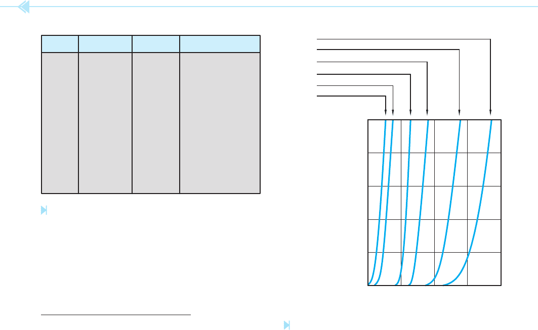
chart in Figure 51–1 shows different- colored LEDs,
the wavelength of light in nanometers, and the
materials used to construct the diode.
LED CHARACTERISTICS
The electrical characteristics of light-emitting diodes
vary considerably from those of the common junc-
tion or recti er diode. Junction diodes have a for-
ward voltage drop of about 0.7 volts for silicon and
0.4 volts for germanium. LEDs have a forward volt-
age drop of about 1.7 volts or greater, depending on
the material the diode is made of. Most light-emitting
diodes are operated at about 20 mA or less current.
A chart showing the typical forward voltage drop of
different diodes is shown in Figure 51–2. Junction
diodes typically have a PIV rating of 100 volts or
greater, but LEDs have a typical PIV rating of about
5 volts. For this reason, when light-emitting diodes
are used in applications where they are intended to
block any amount of reverse voltage they are con-
nected in series with a junction diode.
Testing LEDs
Light-emitting diodes can be tested in a manner
similar to that of testing a junction diode. The LED is
a recti er and should permit current to ow through
it in one direction only. When testing an LED with an
ohmmeter, it must be capable of supplying enough
voltage to overcome the forward conduction voltage
of about 1.7 volts or higher. The meter, however,
must not supply a voltage that is higher than the
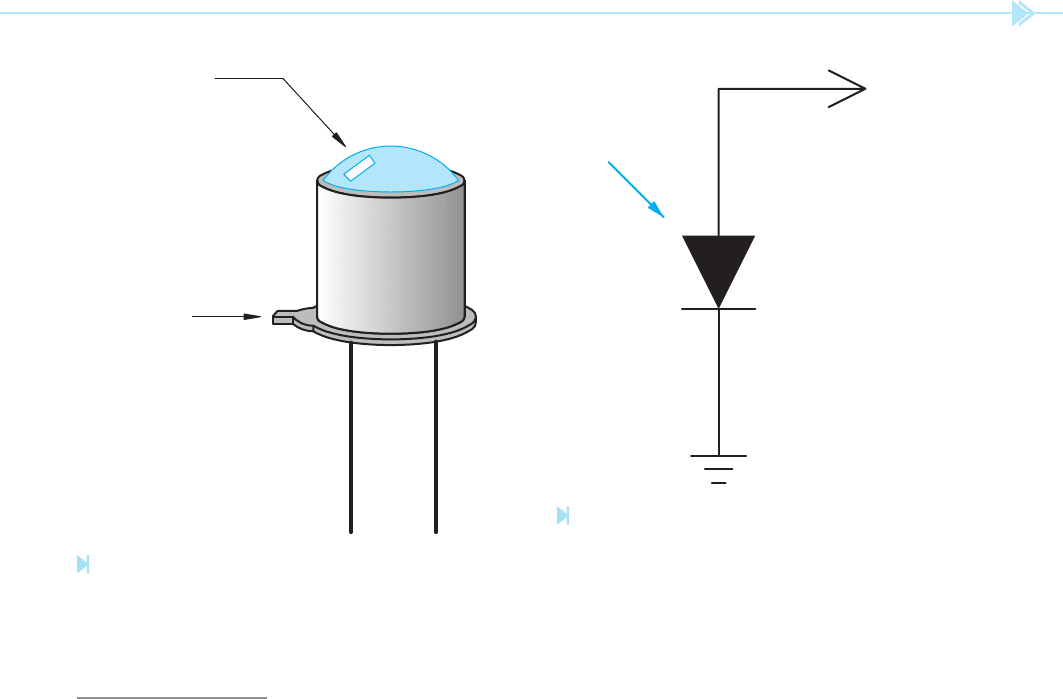
reverse breakdown voltage. The schematic symbol
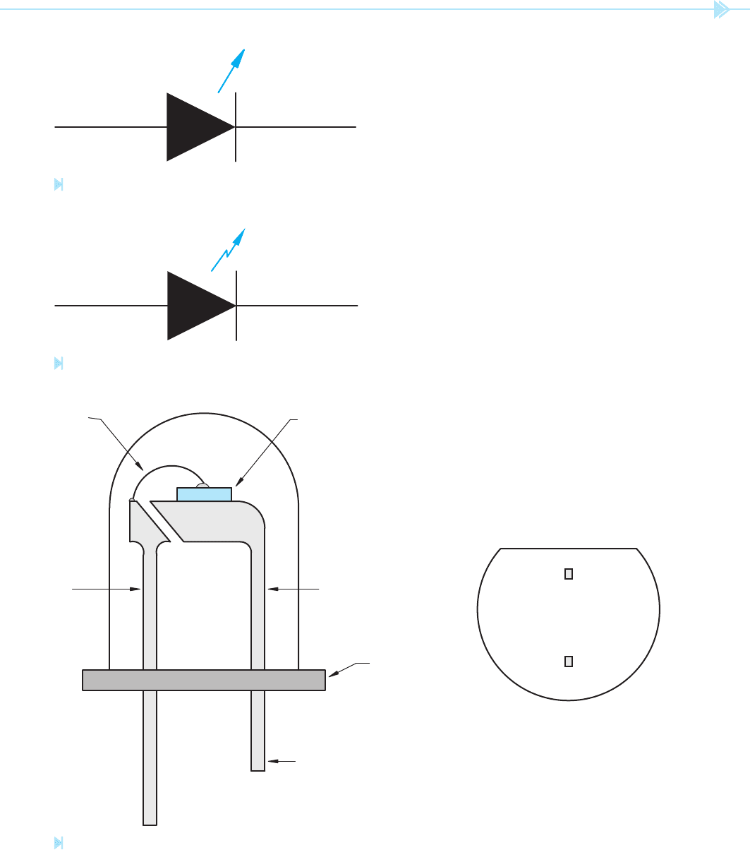
for a light-emitting diode is shown in Figure 51–3.
Some symbols use a straight arrow as shown in
Figure 51–3, and others use a lightning arrow as
shown in Figure 51–4. The lightning arrow symbol
is employed to help prevent the arrow from being
confused with a lead attached to the device. The
important part of the symbol is that the arrow is
pointing away from the diode. This indicates that
light is being emitted or given off by the diode.
LED Lead Identi cation
Light-emitting diodes are housed in many different
case styles. Regardless of the case style, however,
Color Material Dopant Wavelength (nm)
IR GaAs
Zn 900IR GaAs
Si 900–1020
Red GaP Zn,O 700
Red GaAsP — 650
Orange GaAsP N 632
Yellow GaP N,N 590
Yellow GaAsP N 589
Green GaP N 570
Blue SiC — 490
Blue ZnSe — 490
Figure 51–1
The color of an LED is determined by the material it is
made from. (Source: Delmar/Cengage Learning)
0
10 mA
20 mA
30 mA
40 mA
50 mA
1234
FORWARD VOLTAGE DROP
Ge
Si
GaAs
GaAsP
GaP
SiC
Figure 51–2
Forward voltage and current characteristics of diodes.
(Source: Delmar/Cengage Learning)
UNIT 51 Light-Emitting Diodes (LEDs) and Photodiodes 485
there is generally some method of identifying which
lead is the cathode and which is the anode. The
case of most LEDs will have a at side that is located
closer to the cathode lead, Figure 51–5. Also, the
cathode lead is generally shorter.
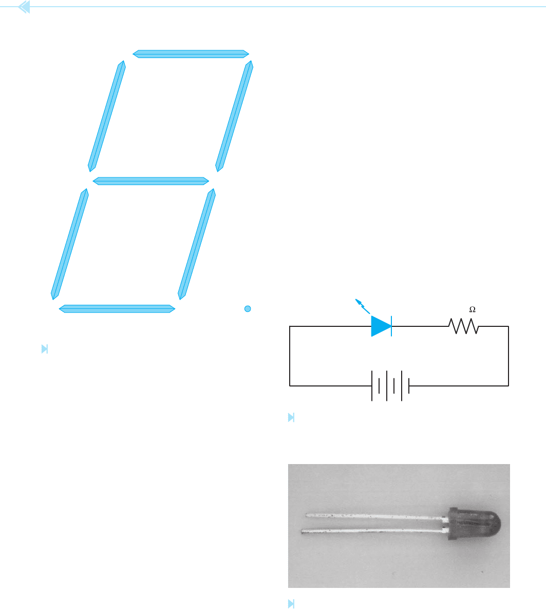
Seven-Segment Displays
A very common device that employs the use of
light-emitting diodes is the seven segment display,
Figure 51–6. The display actually contains eight
LEDs, each segment plus the decimal point. Common
cathode displays have all the cathodes connected
together to form a common point. The display is
energized by connecting a more positive voltage to
the anode lead of each segment. Common anode dis-
plays are energized by connecting the appropriate
cathode lead to a more negative voltage (generally
ground). The seven-segment display can be used to
display any number from 0 to 9.
Figure 51–3
Schematic symbol for a light-emitting diode. (Source: Delmar/
Cengage Learning)
Figure 51–4
LED symbol using lightning arrow. (Source: Delmar/
Cengage Learning)
LED CHIP
WIRE
ANODE POST CATHODE POST
FLAT SIDE
CATHODE LEAD IS
SHORTER THAN
ANODE LEAD
FLAT SIDE CLOSER
TO CATHODE LEAD
CATHODE
ANODE
BOTTOM VIEW
Figure 51–5
Identifying the leads of an LED. (Source: Delmar/Cengage Learning)
486 SECTION 8 Solid-State Devices
Connecting the LED in a Circuit
When used in a circuit, the LED generally operates
with a current of about 20 mA (0.020 A) or less.
Assume that an LED is to be connected in a 12-VDC
circuit and is to have a current draw of approxi-
mately 20 milliamperes. This LED must have a
current-limiting resistor connected in series with it.
Ohm’s law can be used to determine what size resis-
tor should be connected in the circuit.
R ⫽
E
__
I
R ⫽
12
_____
.020
R ⫽ 600 Ω
The nearest standard size resistor without going
below 600 Ω is 620 Ω. A 620 Ω resistor would
be connected in series with the LED, Figure 51–7.
The minimum power rating for the resistor can
also be determined using Ohm’s law. The LED will
have a voltage drop of approximately 1.7 volts.
Because the resistor is connected in series with
the LED, it will have a voltage drop of 10.3 volts.
The power dissipation of the resistor can now be
determined.
P ⫽ E
2
/R
P ⫽
10.3
2
_____
620
P ⫽
106.09
_______
620
P ⫽ 0.171 watt
A ¼ watt resistor can be employed in this circuit. A
light-emitting diode is shown in Figure 51–8.
A
B
C
D
E
F
G
DP
Figure 51–6
Seven-segment display. (Source: Delmar/Cengage Learning)
12 VDC
620
Figure 51–7
Current is limited by a resistor connected in series with
the LED. (Source: Delmar/Cengage Learning)
Figure 51–8
Light-emitting diode. (Source: Delmar/Cengage Learning)
UNIT 51 Light-Emitting Diodes (LEDs) and Photodiodes 487
PHOTODIODES
The photodiode is so named because of its
response to a light source. Photodiodes are housed
in a case that has a window that permits light to
strike the semiconductor material, Figure 51–9.
Photodiodes can be used in two basic ways.
Photovoltaic
Photodiodes can be used as photovoltaic devices.
When in the presence of light, they will produce a
voltage in a manner similar to that of solar cells.
The output voltage is approximately 0.45 volts. The
current capacity is small and use is generally limited
to applications such as operating light-metering
devices. The basic schematic for a photodiode used
as a photovoltaic device is shown in Figure 51–10.
LENS
TAB CLOSEST
TO CATHODE
LEAD
CATHODE ANODE
Figure 51–9
Photodiode. (Source: Delmar/Cengage Learning)
+0.45 V
PHOTODIODE
Figure 51–10
Photodiode used as a photovoltaic device. (Source: Delmar/
Cengage Learning)
Note the symbol used to represent a photo diode.
The arrow pointing toward the diode indicates that
it must receive light to operate.
Photoconductive
Photodiodes can also be used as photoconduc-
tive devices. When used in this manner they
are connected reverse biased, Figure 51–11. In
the presence of darkness, the amount of reverse
current ow is extremely small, similar to that of
a junction diode connected reverse biased. This
current is referred to as the
dark current (I
D
) and is
generally in the range of a few nanoamperes. For
most practical purposes dark current is generally
considered to be zero.
When exposed to light, photons enter the
depletion region and create electron-hole pairs,
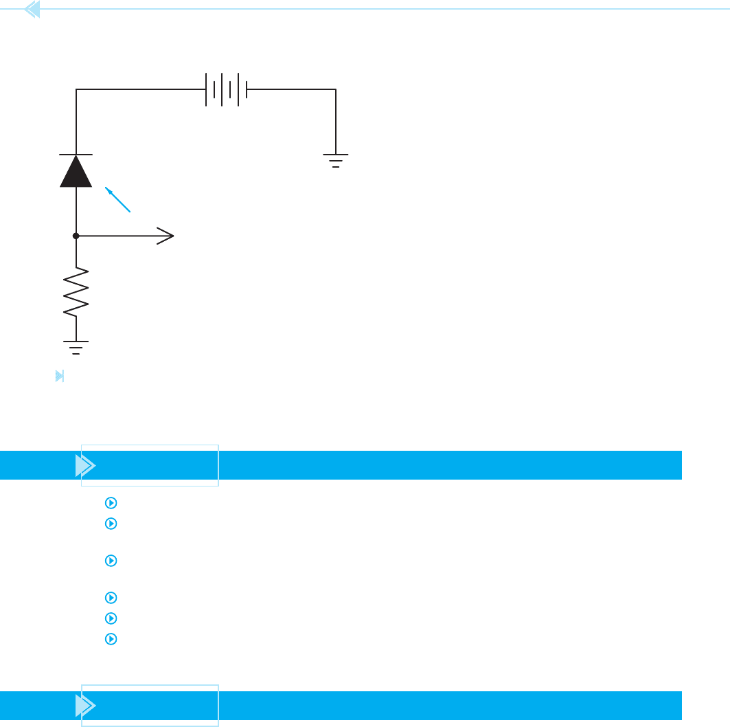
488 SECTION 8 Solid-State Devices
increasing conductivity in the reverse direction.
The increased conduction may permit several mil-
liamperes of current to ow. This is known as light
current
(I
L
). The great advantage of the photodiode
over other photoconductive devices, such as the
cad cell, is speed of operation. Photodiodes can
operate at very high frequencies.
SUMMARY
The light-emitting diode produces a light when current ows through it.
The schematic symbol of an LED is a standard diode symbol with an arrow pointing away
from the symbol. The arrow indicates that light is being emitted by the device.
The schematic symbol for a photodiode is a standard diode symbol with an arrow pointing
toward the symbol. The arrow indicates that light is received by the device.
The forward voltage drop of an LED is approximately 1.7 volts.
Photodiodes are commonly used as photovoltaic devices and as photoconductive devices.
The greatest advantage of photodiodes over other photoconductive devices is speed of
operation.
KEY TERMS
light-emitting diode (LED)
photoconductive
photodiode
photovoltaic
BATTERY
OUTPUT
+
Figure 51–11
Photodiode used as a photoconductive device. (Source:
Delmar/Cengage Learning)

UNIT 51 Light-Emitting Diodes (LEDs) and Photodiodes 489
REVIEW QUESTIONS
1. Will the LED rectify an AC voltage into DC voltage?
2. What is the average voltage drop on an LED?
3. How can the anode and cathode leads of an LED be identi ed?
4. What is the average amount of current permitted to ow through an LED?
5. Can LEDs be tested with most ohmmeters?
6. When used as a photovoltaic device, how much voltage is generally produced by
a photodiode?
7. Explain the difference between the schematic symbol used to indicate an LED and the
symbol used to indicate a photodiode.
8. What is the greatest advantage of a photodiode used as a photoconductive device as
compared with other photoconductive devices such as a cad cell?