Stephen L. Herman, Bennie Sparkman. Electricity and Controls for HVAC-R (6th edition)
Подождите немного. Документ загружается.

540 SECTION 9 Solid-State Controls
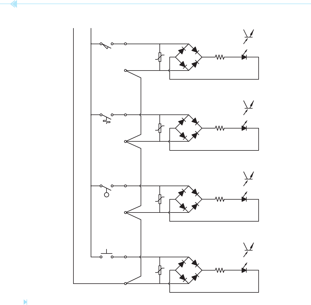
HOT
NEUTRAL
1
2
3
4
COMMON
Figure 58–12
Pilot devices connected to input modules. (Source: Delmar/Cengage Learning)
UNIT 58 Programmable Logic Controllers 541
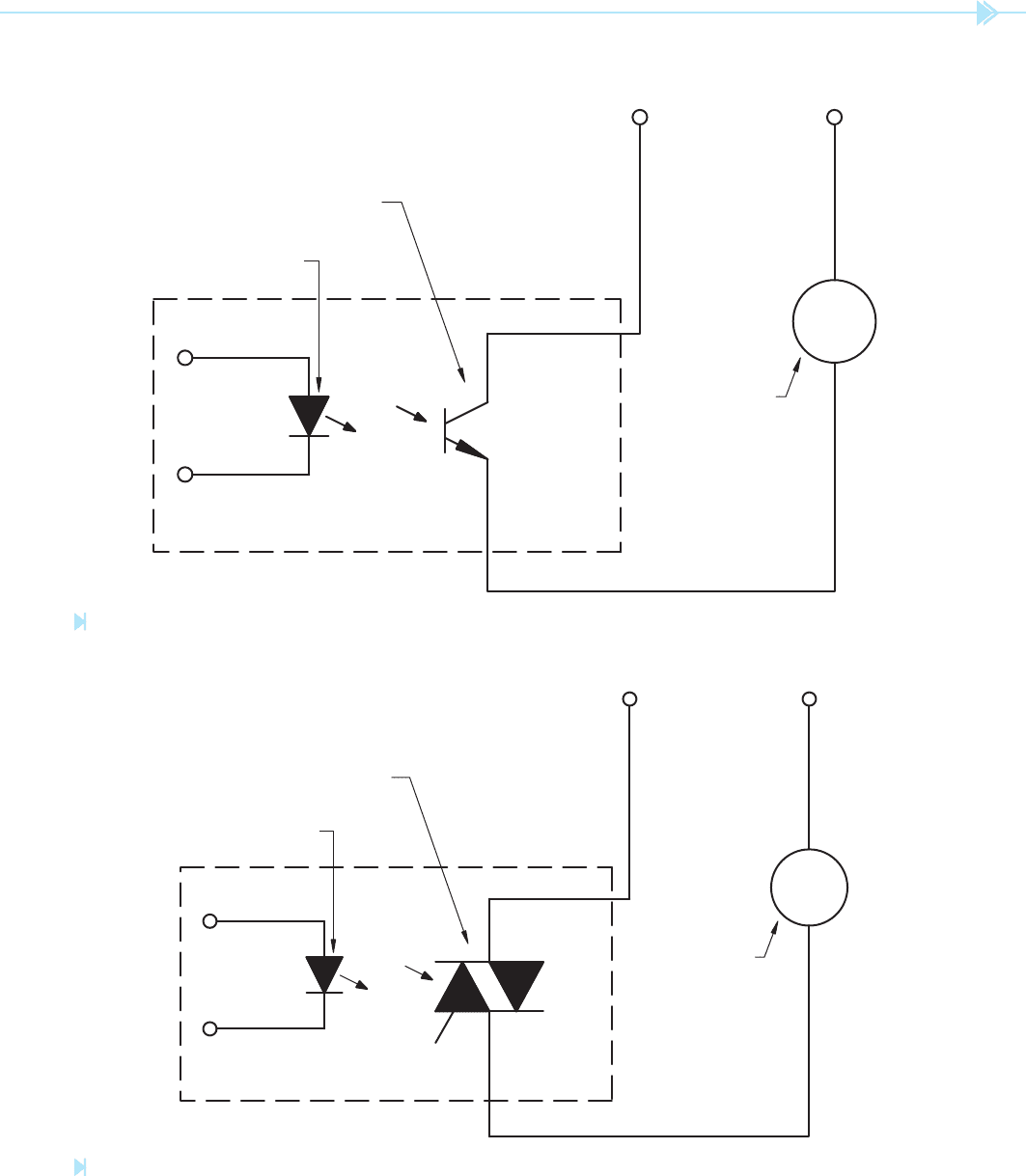
RELAY COIL
+
_
FROM CPU
POWER PHOTOTRANSISTOR
LED
Figure 58–13
A power phototransistor connects a DC load to the line. (Source: Delmar/Cengage Learning)
HOT NEUTRAL
FROM CPU
PHOTOTRIAC
LED
RELAY COIL
Figure 58–14
A triac connects an AC load to the line. (Source: Delmar/Cengage Learning)
542 SECTION 9 Solid-State Controls
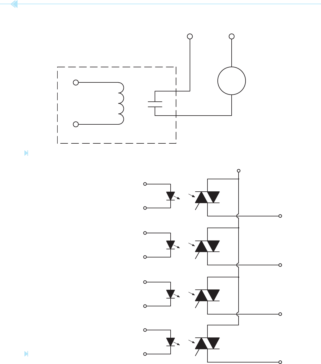
FROM CPU
LOAD
SOURCE VOLTAGE
Figure 58–15
A relay connects the load to the line. (Source: Delmar/Cengage Learning)
HOT
FROM CPU
FROM CPU
FROM CPU
FROM CPU
1
2
3
4
Figure 58–16
Multiple-output module. (Source: Delmar/
Cengage Learning)
UNIT 58 Programmable Logic Controllers 543
INTERNAL RELAYS
The actual logic of the control circuit is performed
by internal relays. An internal relay is an imagi-
nary device that exists only in the logic of the com-
puter. It can have any number of contacts from
one to several hundred, and the contacts can be
programmed normally open or normally closed.
Internal relays are programmed into the logic of the
PLC by assigning them a certain number. Manu-
facturers provide a chart that lists which numbers
can be used to program inputs and outputs, internal
relay coils, timers, counters, and so on. When a coil
is entered at the end of a line of logic and is given
a number that corresponds to an internal relay, it
will act like a physical relay. Any contacts given
the same number as that relay will be controlled by
that relay.
TIMERS AND COUNTERS
Timers and counters are internal relays also. There
is no physical timer or counter in the PLC. They
are programmed into the logic in the same manner
as any other internal relay, by assigning them a
number that corresponds to a timer or counter. The
difference is that the time delay or number of counts
must be programmed when they are inserted into
the program. The number of counts for a counter are
entered using numbers on the keys on the load termi-
nal. Timers are generally programmed in 0.1-second
intervals. Some manufacturers provide a decimal key
and others do not. If a decimal key is not provided,
the time delay is entered as 0.1-second intervals.
If a delay of 10 seconds is desired, for example, the
number 100 would be entered. One hundred tenths
of a second equals 10 seconds.
OFF-DELAY CIRCUIT
Some programmable logic controllers permit a timer
to be programmed as on or off delay, but others
permit only on-delay timers to be programmed.
When a PLC permits only on-delay timers to be
programmed, a simple circuit can be used to per-
mit an on-delay timer to perform the function of
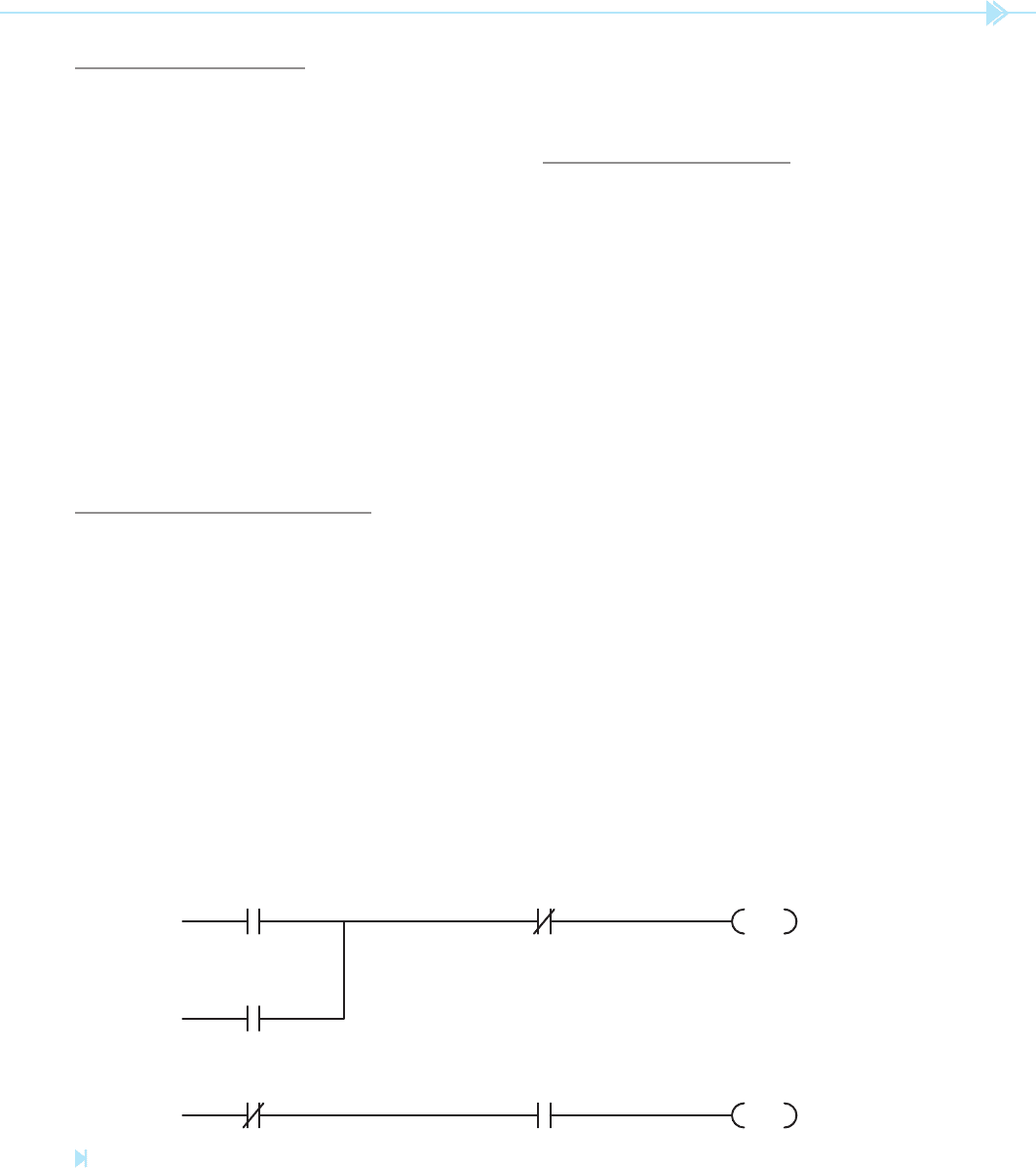
an off-delay timer, Figure 58–17. To understand
the action of the circuit, recall the operation of an
off-delay timer. When the timer coil is energized
the timed contacts change position immediately.
When the coil is deenergized the contacts remain in
their energized state for some period of time before
returning to their normal state. In the circuit shown
in Figure 58–17 it is assumed that contact 400 con-
trols the action of the timer. Coil 400 is an internal
relay coil located somewhere in the circuit. Coil 12
is an output and controls some external device. Coil
TO-1 is an on-delay timer set for 100 tenths of a sec-
ond. When coil 400 is energized, both 400 contacts
change position. The normally open 400 contact
closes and provides a current path to coil 12. The
normally closed 400 contact opens and prevents a
circuit from being completed to coil TO-1 when coil
12 energizes. Note that coil 12 turned on imme-
diately when contact 400 closed. When coil 400
is deenergized, both 400 contacts return to their
normal position. A current path is maintained to
coil 12 by the now closed 12 contact in parallel
400
12
TO-1
12
400
TO-1
12
00100
Figure 58–17
Off-delay timer circuit. (Source: Delmar/Cengage Learning)
544 SECTION 9 Solid-State Controls
with the normally open 400 contact. When the
normally closed 400 contact returns to its normal
position a current path is established to coil TO-1
through the now closed 12 contact. This starts the
time sequence of timer TO-1. After a delay of 10 sec-
onds, the normally closed TO-1 contact opens and
deenergizes coil 12, returning the two 12 contacts
to their normal position. The circuit is now back in
the state shown in Figure 58–16. Note the action
of the circuit. When coil 400 was energized, output
coil 12 turned on immediately. When coil 400 was
deenergized, output 12 remained on for 10 seconds
before turning off.
The number of internal relays and timers con-
tained in a programmable logic controller is deter-
mined by the memory capacity of the computer. As
a general rule, PLCs that have a large I/O capacity
will have a large amount of memory. The use of pro-
grammable logic controllers has steadily increased
since their invention in the late 1960s. A PLC can
replace hundreds of relays and occupy only a frac-
tion of the space. The circuit logic can be changed
easily and quickly without requiring extensive hand
rewiring. They have no moving parts or contacts to
wear out, and their down time is less than that of
an equivalent relay circuit. When replacement is
necessary, they can be reprogrammed from a media
storage device.
The programming methods presented in this text
are general because it is impossible to include exam-
ples of each speci c manufacturer. The concepts
presented in this chapter, however, are common
to all programmable controllers. A programmable
logic controller used to control a DC drive is shown
in Figure 58–18.
Figure 58–18
DC drive unit controlled by a programmable logic
controller. (Courtesy of Reliance Electric).
SUMMARY
Programmable logic controllers were rst used by the automotive industry in the
early 1960s.
The major parts of a programmable logic controller are the power supply, central process-
ing unit, programming terminal, and I/O rack.
The power supply changes AC into DC, and then lters and regulates it to the proper voltage.
The central processing unit performs all the logic functions loaded into memory.
The programming terminal is used to load or amend a program in a programmable
logic controller.
Laptop computers are often employed as programming terminals.
The I/O rack provides inputs and outputs for the programmable logic controller.
Most programmable logic controllers use opto-isolation in the input and output modules.
Input modules provide information to the central processing unit from the outside circuit.

UNIT 58 Programmable Logic Controllers 545
Output modules provide information from the central processing unit to the outside circuit.
Internal relays are relays that exist only in the logic of the computer.
Some internal relays can be employed as counters and timers.
KEY TERMS
central processing unit
(CPU)
illuminated
internal relay
I/O capacity
I/O rack
loading terminal
power supply
programmable logic
controller (PLC)
programming terminal
REVIEW QUESTIONS
1. What industry rst started using programmable logic controllers?
2. Name two differences between PLCs and common home or business computers.
3. Name the four basic sections of a programmable logic controller.
4. In what section of the PLC is the actual logic performed?
5. What device is used to program a PLC?
6. What device separates the central processing unit from the outside world?
7. What is opto-isolation?
8. If an output I/O controls a DC voltage, what solid-state device is used to connect the
load to the line?
9. If an output I/O controls an AC voltage, what solid-state device is used to connect the
load to the line?
10. What is an internal relay?
11. What is the purpose of the key switch located on the front of the CPU in many pro-
grammable logic controllers?
12. What is a software switch?

546
In this unit a relay schematic will be converted
into a diagram used to program a programmable
logic controller. The process to be controlled is
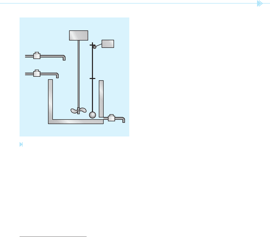
shown in Figure 59–1. A tank is used to mix two
liquids. The control circuit operates as follows:
1. When the start button is pressed, solenoids
A and B energize. This permits the two liquids
to begin lling the tank.
2. When the tank is lled, the oat switch trips.
This deenergizes solenoids A and B and starts
the motor used to mix the liquids together.
3. The motor is permitted to run for one
minute. After one minute has elapsed, the
motor turns off and solenoid C energizes to
drain the tank.
UNIT 59
Programming
a PLC
OBJECTIVES
After studying this unit the student should
be able to:
Convert a relay schematic to a
schematic used for programming
a PLC
Enter a program into a programmable
logic controller
UNIT 59 Programming a PLC 547
4. When the tank is empty, the oat switch
deenergizes solenoid C.
5. A stop button can be used to stop the process
at any point.
6. If the motor becomes overloaded, the action
of the entire circuit will stop.
7. Once the circuit has been energized it will
continue to operate until it is manually
stopped.
CIRCUIT OPERATION
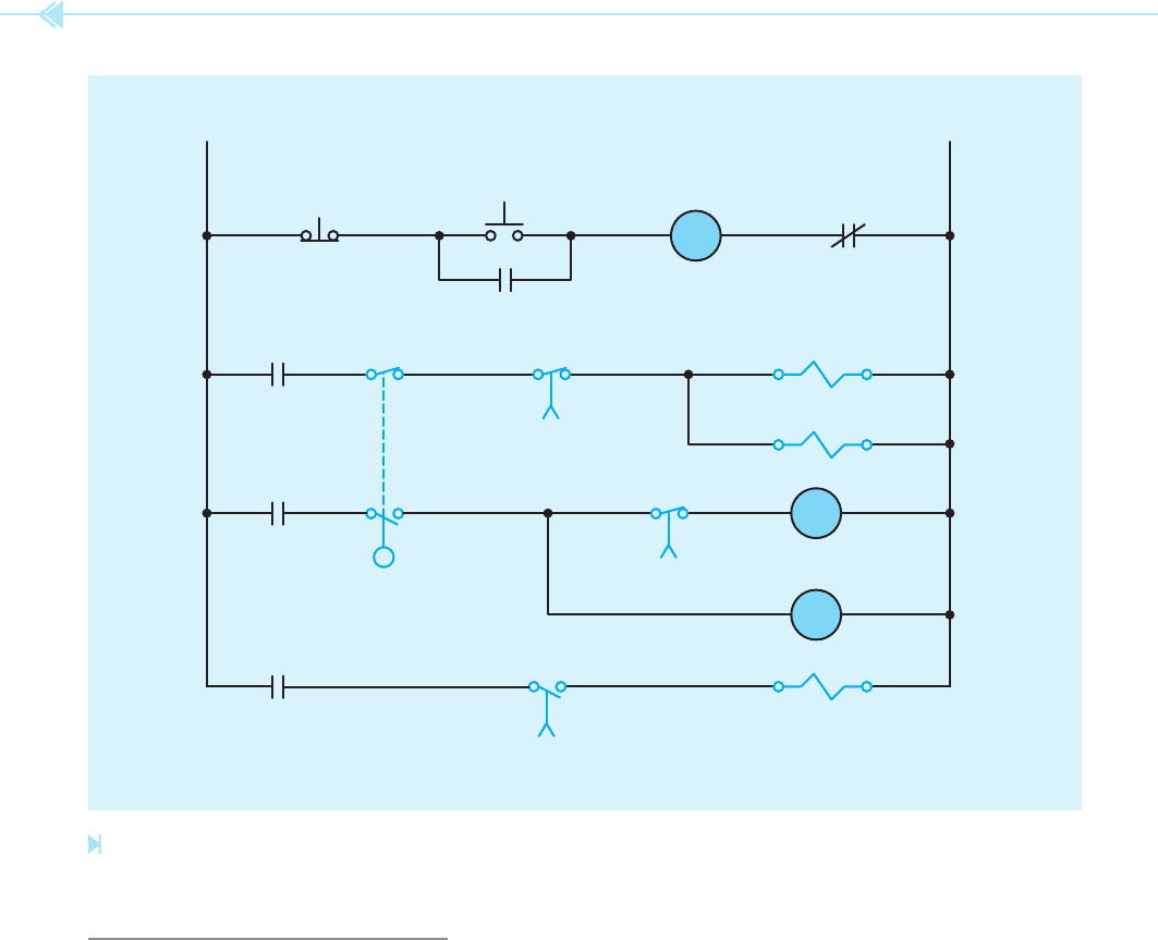
A relay schematic that will perform the logic of this
circuit is shown in Figure 59–2. The logic of this
circuit is as follows:
1. When the start button is pushed, relay coil
CR is energized. This causes all CR contacts to
close. Contact CR-1 is a holding contact used
to maintain the circuit to coil CR when the
start button is released.
2. When contact CR-2 closes, a circuit is com-
pleted to solenoid coils A and B. This permits
the two liquids that are to be mixed together
to begin lling the tank.
3. As the tank lls, the oat rises until the oat
switch is tripped. This causes the normally
closed oat switch contact to open and the
normally open contact to close.
4. When the normally closed oat switch opens,
solenoid coils A and B deenergize and stop the
ow of the two liquids into the tank.
5. When the normally open contact closes, a
circuit is completed to the coil of a motor
starter and the coil of an on-delay timer. The
motor is used to mix the two liquids together.
6. At the end of the one minute time period,
all of the TR contacts change position. The
normally closed TR-2 contact connected
in series with the motor starter coil opens
and stops the operation of the motor. The
normally open TR-3 contact closes and
energizes solenoid coil C which permits liquid
to begin draining from the tank. The normally
closed TR-1 contact is used to assure that
valves A and B cannot be reenergized until
solenoid C deenergizes.
7. As liquid drains from the tank, the oat
drops. When the oat drops far enough, the
oat switch trips and its contacts return to
their normal positions. When the normally
open oat switch contact reopens and
de-energizes coil TR, all TR contacts return to
their normal positions.
8. When the normally open TR-3 contact
reopens, solenoid C deenergizes and closes the
drain valve. Contact TR-2 recloses, but the
motor cannot restart because of the normally
open oat switch contact. When contact
TR-1 recloses, a circuit is completed to sole-
noids A and B. This permits the tank to begin
re lling, and the process starts over again.
9. If the stop button or overload contact opens,
coil CR deenergizes and all CR contacts open.
This deenergizes the entire circuit.
MOTOR
FS
A
B
C
Figure 59–1
Tank used to mix two liquids. (Source: Delmar/Cengage Learning)
548 SECTION 9 Solid-State Controls
DEVELOPING A PROGRAM
This circuit will now be developed into a program
that can be loaded into the programmable control-
ler. Figure 59–3 shows a program being developed
on a computer. Assume that the controller has an
I/O capacity of 32, that I/O terminals 1 through 16
are used as inputs, and that terminals 17 through
32 are used as outputs.
Before a program can be developed for input into
a programmable logic controller, it is necessary to
assign which devices connect to the input and
output terminals. This circuit contains four input
devices and four output devices. It is also assumed
that the motor starter for this circuit contains an
overload relay that contains two contacts instead
of one. One contact is normally closed and will be
connected in series with the coil of the motor starter.
The other contact is normally open and is used to
supply an input to a programmable logic control-
ler. If the motor should become overloaded, the
normally closed contacts will open and disconnect
the motor from the line. The normally open contacts
will close and provide a signal to the programmable
logic controller that the motor has tripped on over-
load. The input devices are as follows:
1. Normally closed stop pushbutton.
2. Normally open start pushbutton.
3. Normally open overload contact.
CR
TR
M
OL
A
NH
CR-1
CR-2
FS
CR-3
CR-4
C
B
TR-1
TR-3
TR-2
Figure 59–2
Relay schematic. (Source: Delmar/Cengage Learning)
UNIT 59 Programming a PLC 549
4. A oat switch that contains both a normally
open and normally closed contact.
The four output devices are:
1. Solenoid valve A.
2. Solenoid valve B.
3. Motor starter coil M.
4. Solenoid valve C.
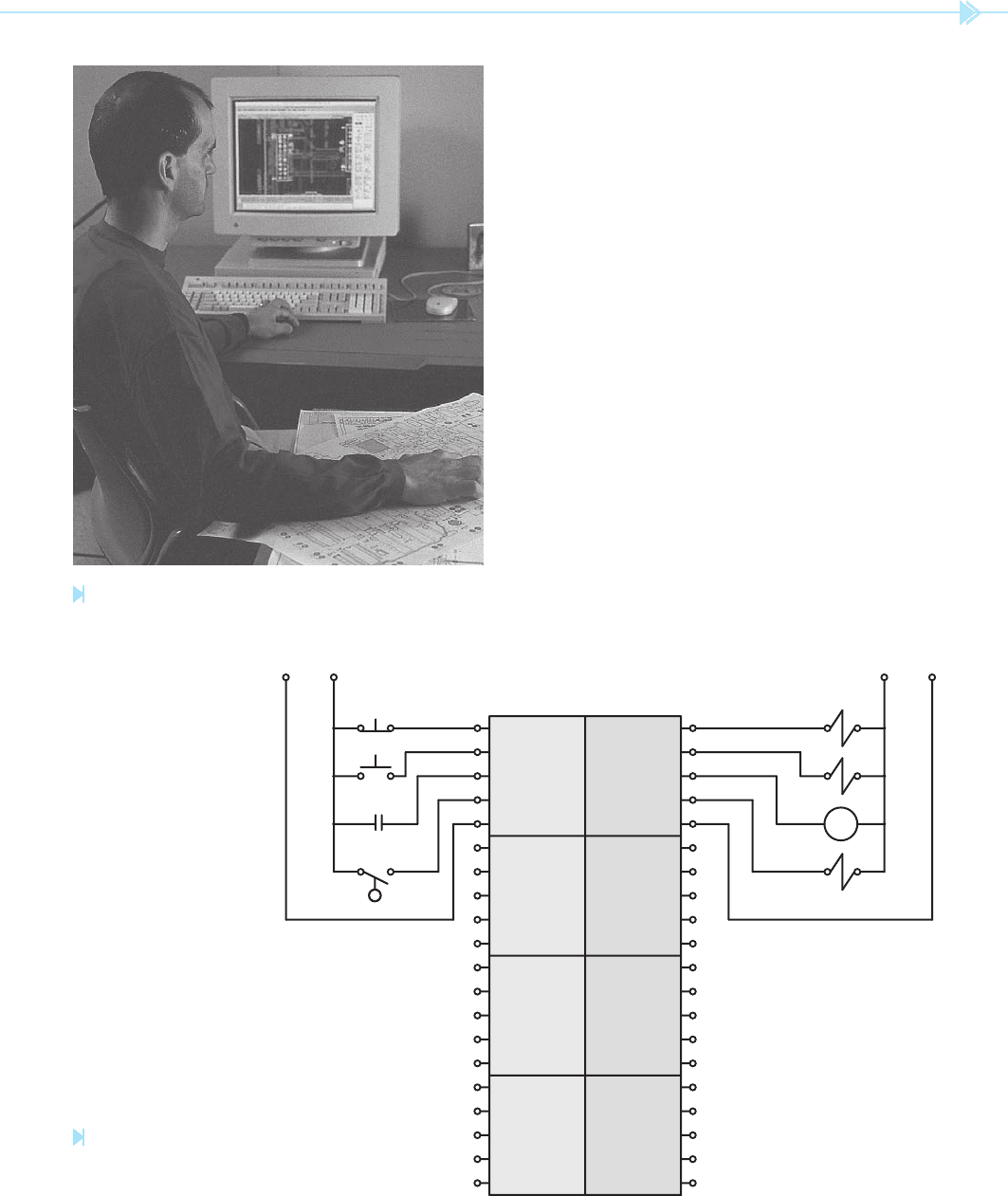
The connection of devices to the inputs and outputs
is shown in Figure 59–4. The normally closed stop
button is connected to input 1, the normally open
start button is connected to input 2, the normally
open overload contact is connected to input 3, and
the oat switch is connected to input 4.
The outputs for this PLC are 17 through 32. Out-
put 17 is connected to solenoid A, output 18 is con-
nected to solenoid B, output 19 is connected to the
coil of the motor starter, and output 20 is connected
to solenoid C. Note that the outputs do not supply the
power to operate the output devices. The outputs
simply complete a circuit. One side of each output
device is connected to the grounded or neutral side
of a 120-VAC power line. The ungrounded or hot
conductor is connected to the common terminal of
Figure 59–3
A program being developed on a programming
terminal. (Courtesy of GE Manuc)
1
2
3
4
C
5
6
7
8
C
9
10
11
12
C
13
14
15
16
C
17
18
19
20
C
21
22
23
24
C
25
26
27
28
C
29
30
31
32
C
INPUT OUTPUT
INPUT OUTPUT
INPUT OUTPUT
INPUT OUTPUT
M
OL
A
B
C
NH HN
Figure 59–4
Component connection
to I/O rack. (Source: Delmar/
Cengage Learning)
