Stephen L. Herman, Bennie Sparkman. Electricity and Controls for HVAC-R (6th edition)
Подождите немного. Документ загружается.

550 SECTION 9 Solid-State Controls
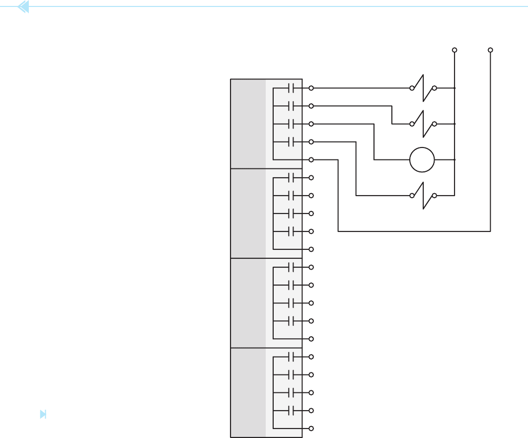
the four outputs. A good way to understand this is to
imagine a set of contacts controlled by each output
as shown in Figure 59–5. When programming the
PLC, if a coil is given the same number as one of the
outputs it will cause that contact to close and con-
nect the load to the line.
Unfortunately, programmable logic controllers
are not all programmed the same way. Almost every
manufacturer employs a different set of coil num-
bers to perform different functions. It is necessary to
consult the manual before programming a PLC with
which you are not familiar. In order to program
the PLC in this example, refer to the information
in Figure 59–6. This chart indicates that numbers
1 through 16 are inputs. Any contact assigned a
number between 1 and 16 will be examined each
time the programmable logic controller scans the
program. If an input has a low (0 volt) state, the con-
tact assigned that number will remain in the state it
was programmed. If the input has a high (120-volt)
state the program will interpret that contact as hav-
ing changed position. If it was programmed as open
the PLC will now consider it as closed.
Outputs are 17 through 32. Outputs are treated
as coils by the PLC. If a coil is given the same num-
ber as an output, that output will turn on (close
17
18
19
20
C
21
22
23
24
C
25
26
27
28
C
29
30
31
32
C
M
A
B
C
HN
Figure 59–5
Output modules complete a circuit to connect
the load to the line.
(Source: Delmar/Cengage Learning)

UNIT 59 Programming a PLC 551
the contact) when the coil is energized. Coils that
control outputs can be assigned internal contacts as
well. Internal contacts are contacts that exist in the
logic of the program only. They do not physically
exist. Because they do not physically exist, a coil
can be assigned as many internal contacts as desired
and they can be normally open or normally closed.
The chart in Figure 59–6 also indicates that
internal relays number from 33 to 103. Internal
relays are like internal contacts. They do not physi-
cally exist. They exist as part of the program only.
They are programmed into the circuit logic by
inserting a coil symbol in the program and assign-
ing it a number between 33 and 103.
Timers and counters are assigned coil numbers
200 through 264, and retentive relays are num-
bered 104 through 134.
CONVERTING THE PROGRAM
Developing a program for a programmable logic
controller is a little different from designing a circuit
with relay logic. There are several rules that must
be followed with almost all programmable logic
controllers.
1. Each line of logic must end with a coil. Some
manufacturers permit coils to be connected
in parallel and some do not.
2. Generally, coils cannot be connected in series.
3. The program will scan in the order that it
is entered.
4. Generally, coils cannot be assigned the
same number. (Some programmable logic
controllers require reset coils to reset coun-
ters and timers. These reset coils can be
assigned the same number as the counter or
timer they reset.)
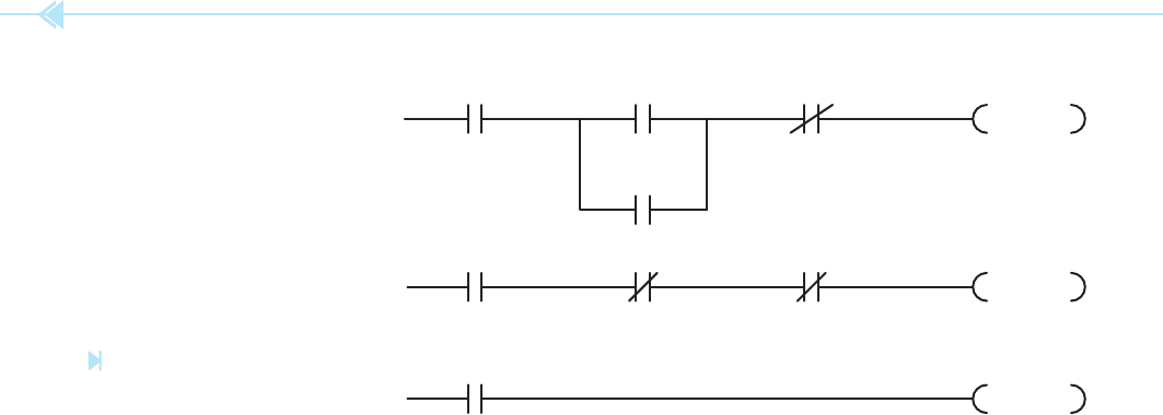
The rst two lines of logic for the circuit shown
in Figure 59–2 can be seen in Figure 59–7. Notice
that contact symbols are used to represent inputs
instead of logic symbols such as pushbuttons, oat
switches, and so on. The programmable logic con-
troller recognizes all inputs as open or closed con-
tacts. It does not know what device is connected to
which input. This is the reason that you must rst
determine which device connects to which input
before a program can be developed. Also notice
that input 1 is shown as a normally open contact.
Referring to Figure 59–4, it can be seen that input 1
is connected to a normally closed pushbutton. The
input is programmed as normally open because the
normally closed pushbutton will supply a high volt-
age to input 1 in normal operation. Because input
1 is in a high state, the PLC will change the state of
the open contact and consider it closed. When the
stop pushbutton is pressed, the input voltage will
change to low and the PLC will change the contact
back to its original open state and cause coil 33
to deenergize.
Referring to the schematic in Figure 59–2, a con-
trol relay is used as part of the circuit logic. Because
the control relay does not directly cause any output
device to turn on or off, an internal relay will be used.
The chart in Figure 59–6 indicates that internal
Inputs 1 – 16
Outputs 17 – 32
Internal Relays 33 – 103
Timers and Counters 200 – 264
Retentative Relays 104 – 134
Figure 59–6
Numbers that correspond to specifi c PLC functions.
(Source: Delmar/Cengage Learning)
123
33
33
Figure 59–7
Lines 1 and 2 of the program.
(Source: Delmar/Cengage Learning)
552 SECTION 9 Solid-State Controls
relays number between 33 and 103. Coil number
33 is an internal relay and does not physically exist.
Any number of contacts can be assigned to this
relay, and they can be open or closed. The number
33 contact connected in parallel with input 2 is the
holding contact labeled CR-1 in Figure 59–2.
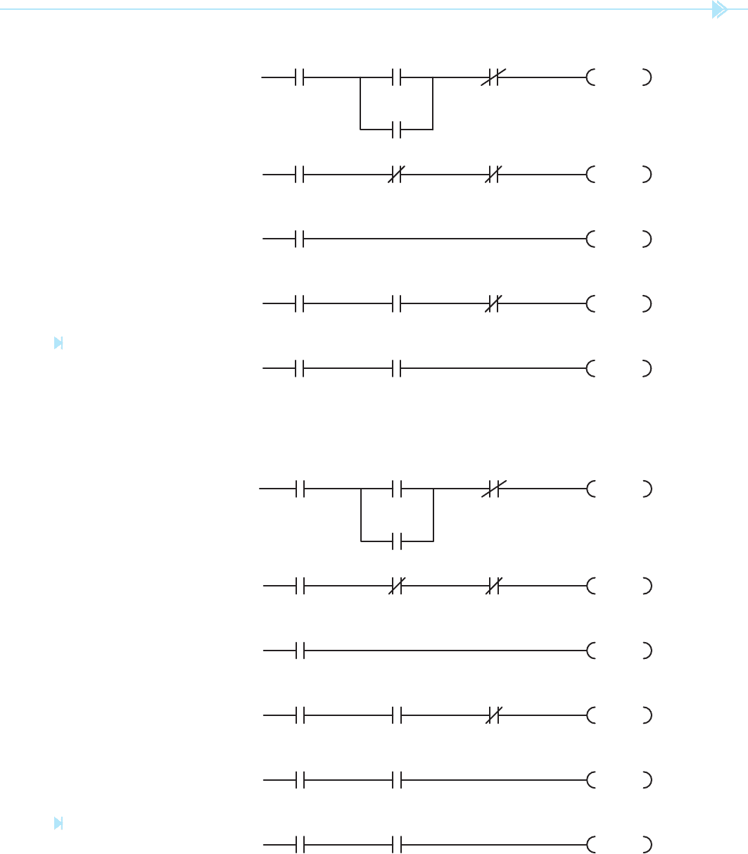
The next two lines of logic are shown in Figure 59–8.
The third line of logic in the schematic in Figure 59–2
contains a normally open CR-2 contact, a normally
closed oat switch contact, a normally closed on-delay
timed contact, and solenoid coil A. The fourth line of
logic contains solenoid coil B connected in parallel
with solenoid coil A. Line three in Figure 59–8 uses
a normally open contact assigned the number 33 for
contact CR-2. A normally closed contact symbol is
assigned the number 4. Because the oat switch is
connected to input number 4, it will control the action
of this contact. As long as input 4 remains in a low
state, the contact will remain closed. If the oat switch
should close, input 4 will become high and the number
4 contact will open.
The next contact is timed contact TR-1. The
chart in Figure 59–6 indicates that timers and
counters are assigned numbers 200 through 264.
In this circuit, timer TR will be assigned number
200. Line three ends with coil number 17. When
coil 17 becomes energized, it will turn on output 17
and connect solenoid coil A to the line.
The schematic in Figure 59–2 shows that sole-
noid coil B is connected in parallel with solenoid
coil A. Most programmable logic controllers do not
permit coils to be connected in parallel. Each line of
logic must end with its own coil. Because solenoid
coil B is connected in parallel with A, they both
operate at the same time. This logic can be accom-
plished by assigning an internal contact the same
number as the coil controlling output 17. Notice
in Figure 59–8 that when coil 17 energizes it will
cause contact 17 to close and energize output 18 at
the same time.
In Figure 59–9, lines 5 and 6 of the schematic
are added to the program. A normally open contact
assigned number 33 is used as for contact CR-3. A
normally open contact assigned the number 4 is
controlled by the oat switch, and a second nor-
mally closed timed contact controlled by timer 200
is programmed in line 5. The output coil is assigned
the number 19. When this coil energizes it turns
on output 19 and connects motor starter coil M to
the line.
Line 6 contains timer coil TR. Notice in Figure 59–2
that coil TR is connected in parallel with contact
TR-2 and coil M. As was the case with solenoid coils
A and B, coil TR cannot be connected in parallel with
coil M. According to the schematic in Figure 59–2,
coil TR is actually controlled by contacts CR-3 and
the normally open oat switch. This logic can be
accomplished as shown in Figure 59–9 by connect-
ing coil T200 in series with contacts assigned the
numbers 33 and 4. Float switches do not normally
contain this many contacts, but because the physical
oat switch is supplying a high or low voltage to
input 4, any number of contacts assigned the number
4 can be used.
The last line of the program is shown in
Figure 59–10. A normally open contact assigned
123
33
33
33 4 T200
17
18
17
Figure 59–8
Lines 3 and 4 of the circuit are
added. (Source: Delmar/Cengage Learning)
UNIT 59 Programming a PLC 553
123
33
33
33 4 T200
17
18
17
33
4
T200
19
33 4
T200
60 sec.
Figure 59–9
Lines 5 and 6 are added to the
program. (Source: Delmar/Cengage Learning)
123
33
33
33 4 T200
17
18
17
33
4
T200
19
33 4
T200
60 sec.
33 T200
20
Figure 59–10
Line 7 of the program. (Source: Delmar/
Cengage Learning)

554 SECTION 9 Solid-State Controls
the number 33 is used for contact CR-4 and a nor-
mally open contact controlled by timer T200 is used
for the normally open timed contact labeled TR-3.
Coil 20 controls the operation of solenoid coil C.
The circuit shown in Figure 59–2 has now been
converted to a program that can be loaded into
a programmable logic controller. The process is
relatively simple if the rules concerning PLCs are
followed.
ENTERING A PROGRAM
The manner in which a program is entered into the
memory of the PLC is speci c to the manufacturer
and type of programming terminal used. Some pro-
gramming terminals employ keys that contain con-
tact, coil, and rung symbols to basically draw the
program as it is entered. Small programming termi-
nals may require that the program be entered in a
language called Boolean. Boolean uses statements
such as and, or, not, and out to enter programs.
Contacts connected in series, for example, would
be joined by and statements, and contacts that are
connected in parallel with each other would be pro-
grammed with or statements. In order to program a
contact normally closed instead of normally open,
the not statement is used. Different PLCs also require
the use of different numbers to identify particular
types of coils. One manufacturer may use any num-
ber between 600 and 699 to identify coils that are
used as timer and counters. Another manufacturer
may use any number between 900 and 999 to iden-
tify coils that can be used as timers and counters.
When programming a PLC, it is always necessary
to rst become familiar with the programming
requirements of the model and manufacturer of the
programmable logic controller being programmed.
PROGRAMMING
CONSIDERATIONS
When developing a program for a programmable
logic controller, there are certain characteristics of
a PLC that should be considered. One of these is the
manner in which a programmable logic controller
performs its functions. Programmable logic control-
lers operate by scanning the program that has been
entered into memory. This process is very similar
to reading a book. It scans from top to bottom and
from left to right. The computer scans the program
one line at a time until it reaches the end of the pro-
gram. It then resets any output conditions that have
changed since the previous scan. The next step is to
check all inputs to determine if they are high (power
applied to that input point) or low (no power applied
to that input point). This information is available for
the next scan. The next step is to update the display
of the programming terminal if one is connected.
The last step is to reset the
“watchdog” timer.
Most PLCs contain a timer that runs continually
when the PLC is in the RUN mode. The function of
this timer is to prevent the computer from becoming
hung in some type of loop. If the timer is not reset at
the end of each scan, the watchdog timer will reach
zero and all outputs will be turned off. Although this
process sounds long, it actually takes place in a few
milliseconds. Depending on the program length, it
may be scanned several hundred times each second.
The watchdog timer duration is generally set for
about twice the amount of time necessary to com-
plete one scan.
Scanning can eliminate some of the problems
with contact races that occur with relay logic.
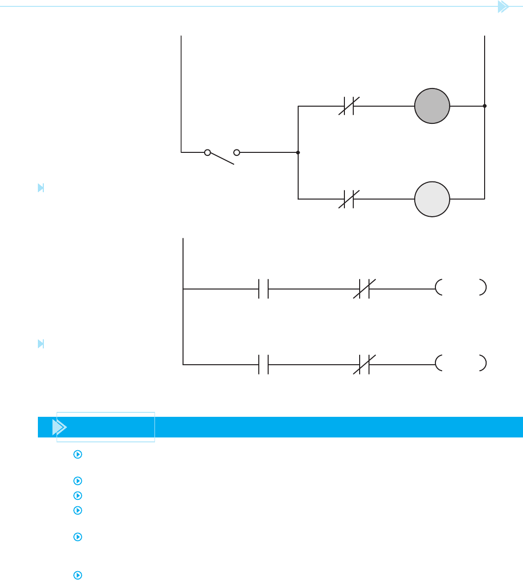
The circuit shown in Figure 59–11 contains two
control relay coils. A normally closed contact, con-
trolled by the opposite relay, is connected in series
with each coil. When the switch is closed, which
relay will turn on and which will be locked out of the
circuit? This called a contact race. The relay that is
turned on depends on which one managed to open
its normally closed contact
rst and break the circuit
to the other coil. There is no way to really know
which relay will turn on and which will remain off.
There is not even a guarantee that the same relay
will turn on each time the switch is closed.
Programmable logic controllers eliminate the
problem of contact races. Because the PLC scans the
program in a manner similar to reading a book, if
it is imperative that a certain relay turn on before
another one, simply program the one that must
turn on rst ahead of the other one. A similar circuit
is shown in Figure 59–12. When contact 1 closes,
coil 100 will always be the internal relay that turns
on because it is scanned before coil 101.
UNIT 59 Programming a PLC 555
SUMMARY
As a general rule, the schematic diagrams used for relay logic must be changed before they
can be loaded into a programmable logic controller.
Each line of logic must end with a coil.
All inputs are assumed to be normally open.
When a normally closed component is connected to the input of a programmable logic
controller, the logic of the program must be reversed for that input.
Before a program can be developed, the sensor devices such as pushbuttons, limit switches,
and oat switches must be assigned to an input. Outputs such as solenoid coils, pilot lights,
and relay coils must be assigned to an output.
Outputs do not supply power to operate devices.
CR2
CR1
CR1
CR2
120 VAC
Figure 59–11
A contact race can exist in relay
control circuits. (Source: Delmar/
Cengage Learning)
1 101
1 100
100
101
Figure 59–12
Scanning eliminates contact
races in PLC logic. (Source: Delmar/
Cengage Learning)

556 SECTION 9 Solid-State Controls
KEY TERMS
Boolean
contact race
input
output
relay schematic
watchdog timer
REVIEW QUESTIONS
1. Why are NEMA symbols such as pushbuttons, oat switches, and limit switches not
used in programmable logic controller schematics?
2. How are such components as coils and contacts identi ed and distinguished from
others in a PLC schematic?
3. Why are normally closed components such as stop pushbuttons programmed
normally open instead of normally closed when entering a program into the memory
of a PLC?
4. What is an internal relay?
5. Why is the output of a PLC used to energize the coil of a motor starter instead of ener-
gizing the motor directly?
6. List four basic rules for developing a program for a PLC.
7. A programmable logic controller requires that times be programmed in 0.1-second
intervals. What number should be entered to produce a time delay of 3 minutes?
8. When programming in Boolean, what statement should be used to connect compo-
nents in series?
9. When programming in Boolean, what statement should be used to connect compo-
nents in parallel?
10. In a control circuit, it is imperative that a coil energize before another one. How can
this be done when entering a program into the memory of the PLC?
11. What is the function of a watchdog timer?

557
Many of the programmable controllers found in
industry are designed to accept analog as well as
digital inputs. Analog means continuously varying.
These inputs are designed to sense voltage, current,
speed, pressure, proximity, temperature, and so on.
When an
analog input is used, such as a thermo-
couple for measuring temperature, a special module
that mounts on the I/O rack is used. These types of
sensors are often used with set point detectors that
can be used to trigger alarms and turn on or off cer-
tain processes. For example, the voltage produced
by a thermocouple will increase with a change of
temperature. Assume that you want to sound an
alarm if the temperature of an object reaches a cer-
tain level. The detector is preset with a particular
voltage. As the temperature of the thermocouple
UNIT 60
Analog
Sensing for
Programmable
Controllers
OBJECTIVES
After studying this unit the student should
be able to:
Describe the differences between
analog and digital inputs
Discuss precautions that should be
taken when using analog inputs
Describe the operation of a differential
amplifi er
558 SECTION 9 Solid-State Controls
increases, its output voltage increases also. When
the voltage of the thermocouple becomes greater
than the preset voltage, an alarm sounds.
INSTALLATION
Most analog sensors can produce only very weak
signals. Zero to 10 volts or 4 to 20 milliamps is com-
mon. In an industrial environment where intense
magnetic elds and large voltage spikes abound, it
is easy to lose the input signal amid the electrical
noise. For this reason, special precautions should
be taken when installing the signal wiring between
the sensor and input module. These precautions are
particularly important when using analog inputs,
but they should be followed when using digital
inputs also.
KEEP WIRE RUNS SHORT
Try to keep wire runs as short as possible. The lon-
ger a wire run is, the more surface area of wire there
is to pick up stray electrical noise.
PLAN THE ROUTE OF
THE SIGNAL CABLE
Before starting, plan how the signal cable should be
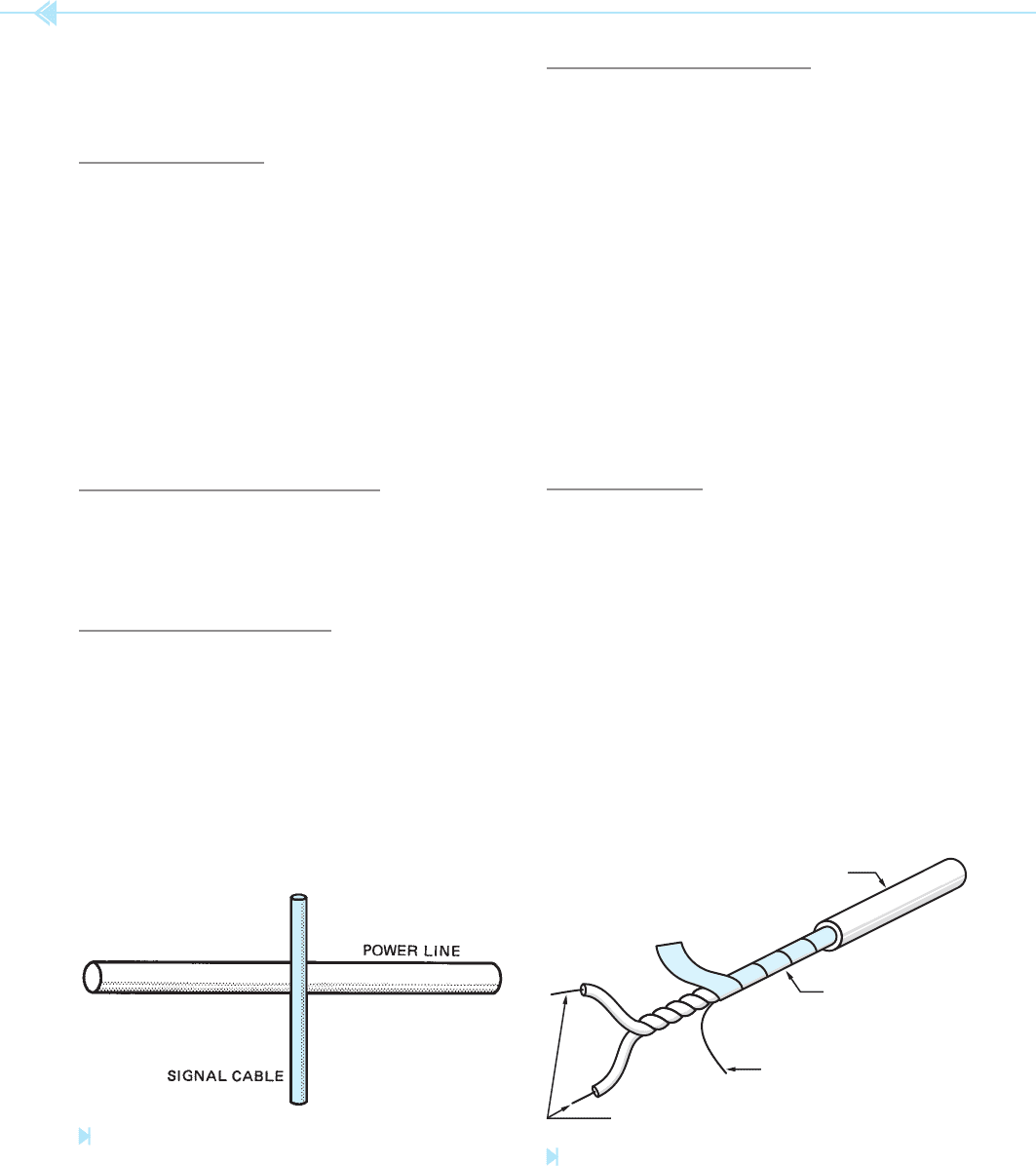
installed. Never run signal wire in the same conduit
with power wiring. Try to run signal wiring as far
away from power wiring as possible. When it is
necessary to cross power wiring, install the signal
cable so that it crosses at a right angle as shown in
Figure 60–1.
USE SHIELDED CABLE
Shielded cable is generally used for the installa-
tion of signal wiring. One of the most common types,
Figure 60–2, uses twisted wires with a Mylar foil
shield. The ground wire must be grounded if the
shielding is to operate properly. This type of shielded
cable can provide a noise reduction ratio of
about 30,000:1.
Another type of signal cable uses a twisted pair
of signal wires surrounded by a braided shield. This
type of cable provides a noise reduction of about
300:1.
Common coaxial cable should be avoided. This
cable consists of a single conductor surrounded by
a braided shield. This type of cable offers very poor
noise reduction.
GROUNDING
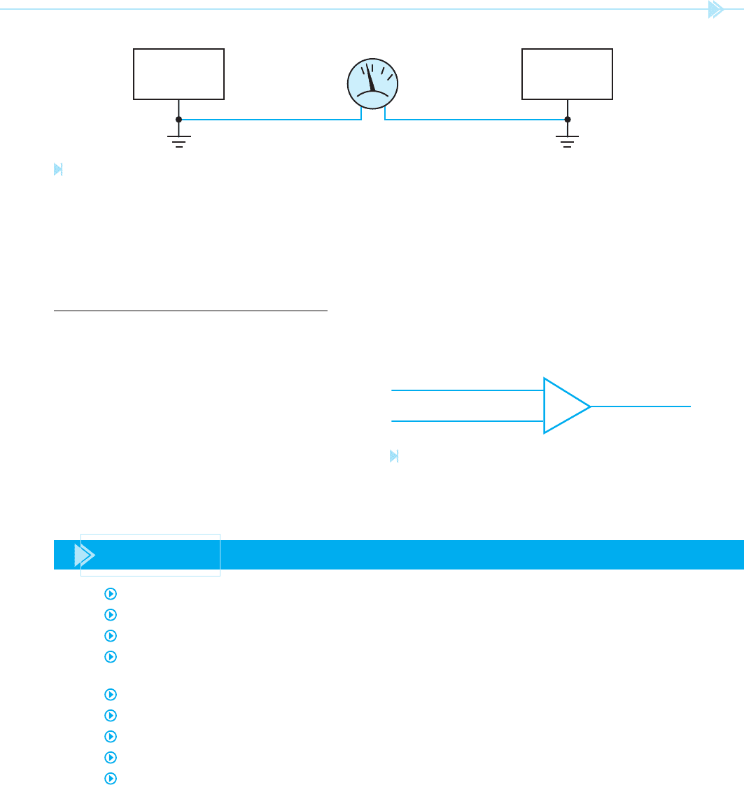
Ground is generally thought of as being electri-
cally neutral or zero at all points. This may not be
the case in practical application, however. It is not
uncommon to nd different pieces of equipment
that have ground levels that are several volts apart,
Figure 60–3.
One method that is sometimes used to overcome
this problem is to use large cable to tie the two pieces
of equipment together. This forces them to exist
at the same potential. This method is sometimes
referred to as the brute force method.
Figure 60–1
Signal cable crosses power line at right angle.
(Source: Delmar/Cengage Learning)
INSULATION
SHIELD
GROUND WIRE
CONDUCTORS
Figure 60–2
Shielded cable. (Source: Delmar/Cengage Learning)
UNIT 60 Analog Sensing for Programmable Controllers 559
module, but induced noise is at a level of 5 volts. In
this case the noise level is 100 times greater than the
signal level. The induced noise level, however, is the
same for both of the input conductors. The differen-
tial ampli er, therefore, ignores the 5-volt noise and
ampli es only the voltage difference which is the
50 millivolts.
Where the brute force method is not practical,
the shield of the signal cable is grounded at only one
end. The preferred method is generally to ground
the shield at the sensor.
THE DIFFERENTIAL AMPLIFIER
An electronic device that is often used to help over-
come the problem of induced noise is the differen-
tial ampli er shown in Figure 60–4. This device
detects the voltage difference between the pair of
signal wires and ampli es this difference. Because
the induced noise level should be the same in both
conductors, the ampli er will ignore the noise. For
example, assume an analog sensor is producing a
50 millivolt signal. This signal is applied to the input
SENSOR
I/O TRACK
VOLTMETER
0
Figure 60–3
All grounds are not equal. (Source: Delmar/Cengage Learning)
INPUT FROM SENSOR
OUTPUT
+
–
Figure 60–4
Differential amplifi er detects difference of signal level.
(Source: Delmar/Cengage Learning)
SUMMARY
Analog inputs sense a range of values instead of operating in an on or off mode.
Most analog inputs operate with a standard of 4 to 20 milliamps.
Special precautions should be used when installing analog inputs.
Wire runs should be kept as short as possible. This reduces the surface of the wire that is
susceptible to electrical noise.
Signal wiring should never be run close to power wiring.
When a signal wire must cross power wiring, it should cross at a 90° angle.
Signal inputs should be run with shielded cable.
The shield of shielded cable should be grounded, generally at the sensor.
Differential ampli ers are sometimes used to help eliminate electrical noise induced in the
signal cable.
