Stephen L. Herman, Bennie Sparkman. Electricity and Controls for HVAC-R (6th edition)
Подождите немного. Документ загружается.

150 SECTION 3 Motors
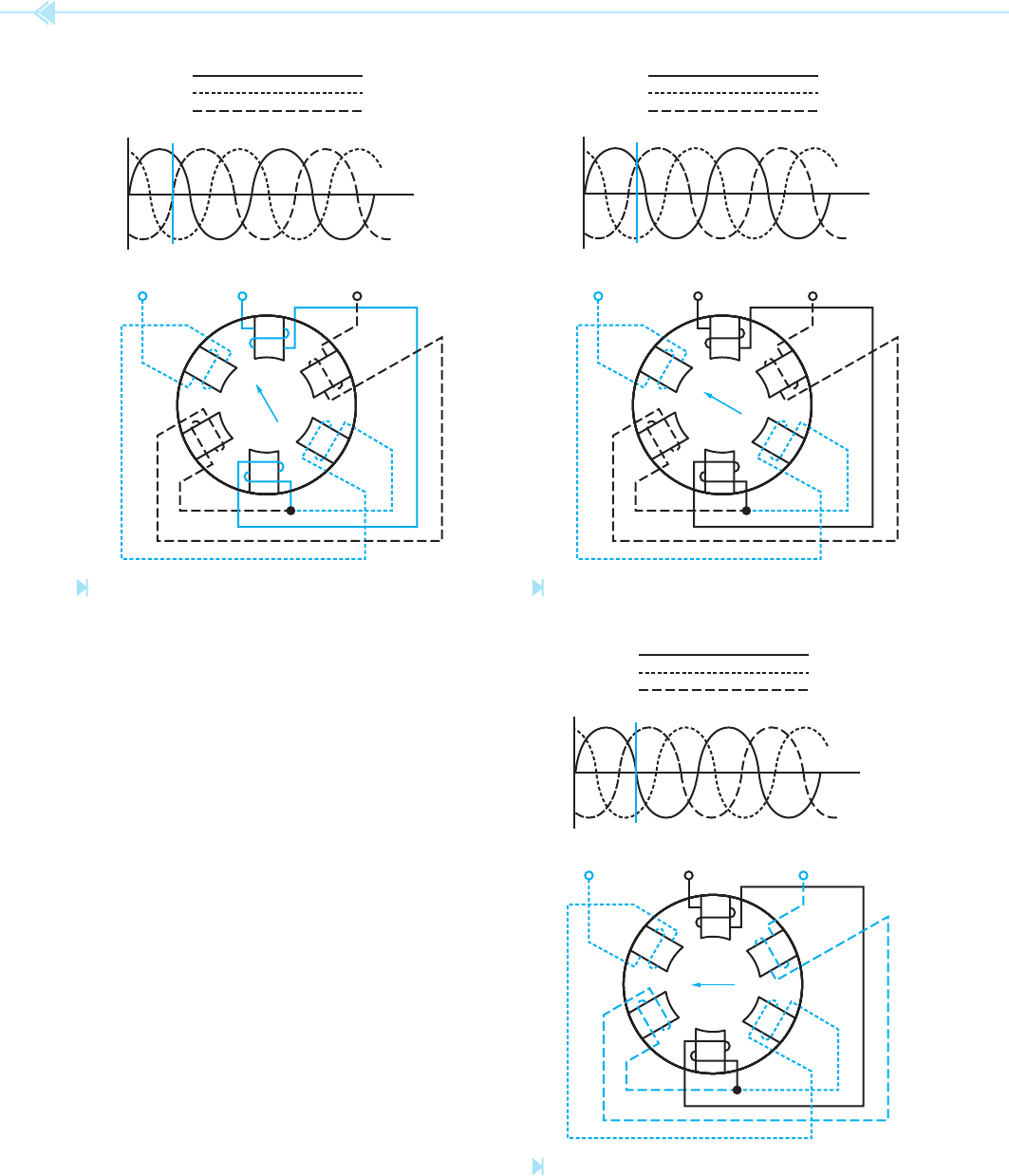
In Figure 14–1D, line C indicates that line 2 is at
its maximum negative peak and that lines 1 and 3
are less than maximum positive. The magnetic eld
at this point is concentrated between pole pieces 2A
and 2B.
In Figure 14–1E, line D indicates that line 1 is
zero. Lines 2 and 3 are less than maximum and in
opposite directions. At this point, the magnetic eld
is concentrated between the pole pieces of phase 2
and phase 3.
In Figure 14–1F, line E indicates that phase 3 is
at its maximum positive peak and lines 1 and 2 are
less than maximum and in the opposite direction.
The magnetic eld at this point is concentrated
between pole pieces 3A and 3B.
In Figure 14–1G, line F indicates that phase 2
is 0. Line 3 is less than maximum positive; and line 1
is less than maximum negative. The magnetic eld
at this time is concentrated between the pole pieces
of phase 1 and phase 3.
L
1
L
2
L
3
1A
2A
3A
2B
1B
3B
L
1
L
2
L
3
B
Figure 14–1C
The magnetic fi eld is concentrated between
phases 1 and 2. (Source: Delmar/Cengage Learning)
L
1
L
2
L
3
1A
2A
3A
2B
1B
3B
L
1
L
2
L
3
C
Figure 14–1D
The magnetic fi eld is concentrated between the poles
of phase 1. (Source: Delmar/Cengage Learning)
L
1
L
2
L
3
1A
2A
3A
2B
1B
3B
L
1
L
2
L
3
D
Figure 14–1E
The magnetic fi eld is concentrated between phases 2 and 3.
(Source: Delmar/Cengage Learning)
UNIT 14 Three-Phase Motor Principles 151
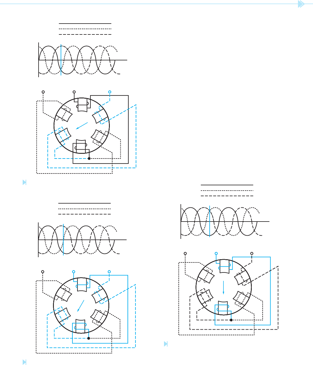
In Figure 14–1H, line G indicates that phase 1
is at its maximum negative peak; and phase 2
and 3 are less than maximum and in the opposite
direction. Notice that the magnetic eld is again
concentrated between pole pieces 1A and 1B. This
time, however, the magnetic polarity is reversed
because the current has reversed in the stator
winding.
In Figure 14–1I, line H indicates phase 2 is at its
maximum positive peak and phases 1 and 3 are less
than maximum and in the negative direction. The
magnetic eld is concentrated between pole pieces
2A and 2B.
In Figure 14–1J, line 1 indicates that phase 3
is maximum negative; and phases 1 and 2 are less
than maximum in the positive direction. The mag-
netic eld at this point is concentrated between pole
pieces 3A and 3B.
In Figure 14–1K, line J indicates that phase 1
is at its positive peak; and phases 2 and 3 are less
than maximum and in the opposite direction. The
L
1
L
2
L
3
1A
2A
3A
2B
1B
3B
L
1
L
2
L
3
E
Figure 14–1F
The magnetic fi eld is concentrated between the poles
of phase 3. (Source: Delmar/Cengage Learning)
L
1
L
2
L
3
1A
2A
3A
2B
1B
3B
L
1
L
2
L
3
F
Figure 14–1G
The magnetic fi eld is concentrated between phases 1 and 3.
(Source: Delmar/Cengage Learning)
L
1
L
2
L
3
1A
2A
3A
2B
1B
3B
L
1
L
2
L
3
G
Figure 14–1H
The magnetic fi eld is concentrated between the poles of
phase 1. (Source: Delmar/Cengage Learning)
152 SECTION 3 Motors
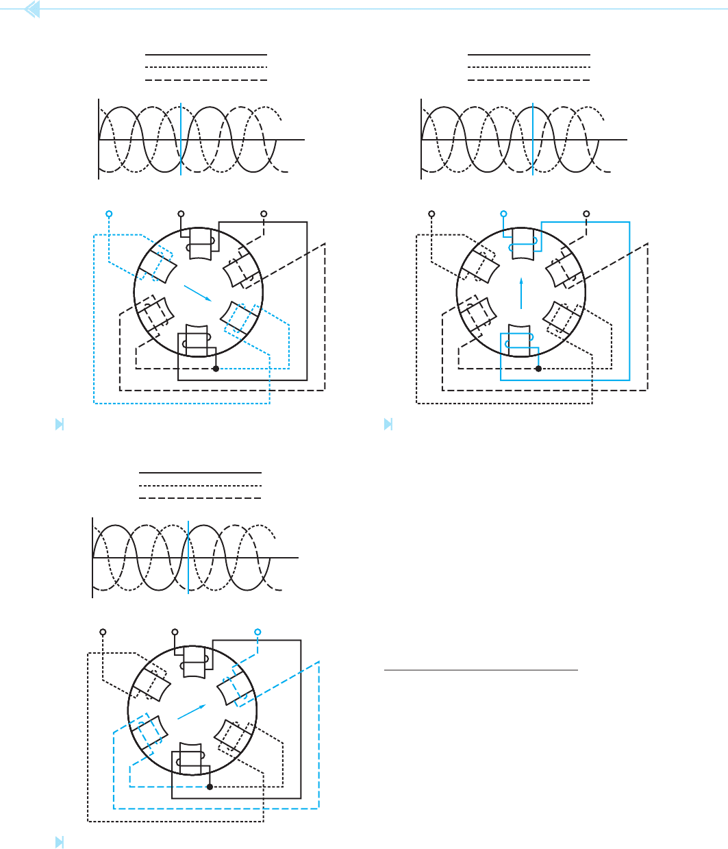
magnetic eld is again concentrated between pole
pieces 1A and 1B. Notice that in one complete cycle
of three-phase voltage, the magnetic eld has rotated
360° around the inside of the stator winding.
If any two of the stator leads is connected to a
different line, the relationship of the voltages will
change and the magnetic eld will rotate in the
opposite direction. The direction of rotation of a
three-phase motor can be reversed by changing any
two stator leads.
SYNCHRONOUS SPEED
The speed at which the magnetic eld rotates is
known as the synchronous speed. The synchro-
nous speed of a three-phase motor is determined by
two factors. These are:
1. The number of stator poles.
2. The frequency of the AC line.
Because 60 Hz is a standard frequency throughout
the United States and Canada, the following gives
L
1
L
2
L
3
1A
2A
3A
2B
1B
3B
L
1
L
2
L
3
H
Figure 14–1I
The magnetic fi eld is concentrated between the poles
of phase 2. (Source: Delmar/Cengage Learning)
L
1
L
2
L
3
1A
2A
3A
2B
1B
3B
L
1
L
2
L
3
I
Figure 14–1J
The magnetic fi eld is concentrated between the poles
of phase 3. (Source: Delmar/Cengage Learning)
L
1
L
2
L
3
1A
2A
3A
2B
1B
3B
L
1
L
2
L
3
J
Figure 14–1K
The magnetic fi eld has rotated 360°.
(Source: Delmar/Cengage Learning)
UNIT 14 Three-Phase Motor Principles 153
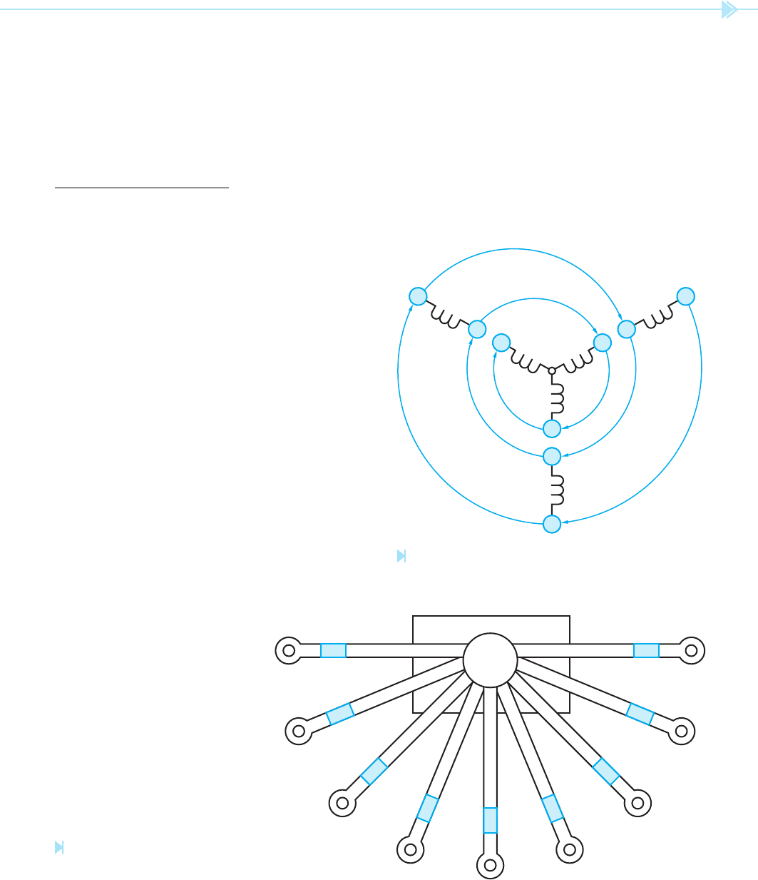
is a schematic diagram, and that when connecting
a three-phase motor for operation at the proper
voltage, the leads will look more like Figure 14–3.
This gure illustrates the leads coming out of the
terminal connection box on the motor. Some leads
are numbered with metal or plastic bands on the
wires, and some leads have numbers printed on the
insulation of the wire.
Figure 14–4 shows the stator connection for
operation on a 480-volt line. Figure 14–5 shows
the synchronous speeds for motors with different
numbers of poles.
2 Poles 3,600 RPM
4 Poles 1,800 RPM
6 Poles 1,200 RPM
8 Poles 900 RPM
STATOR WINDINGS
The stator windings of three-phase motors are con-
nected in either a wye or delta. Some stators are
designed in such a manner as to be connected in
either wye or delta, depending on the operation of
the motor. Some motors, for example, are started as a
wye-connected stator to help reduce starting current,
and then changed to a delta connection for running.
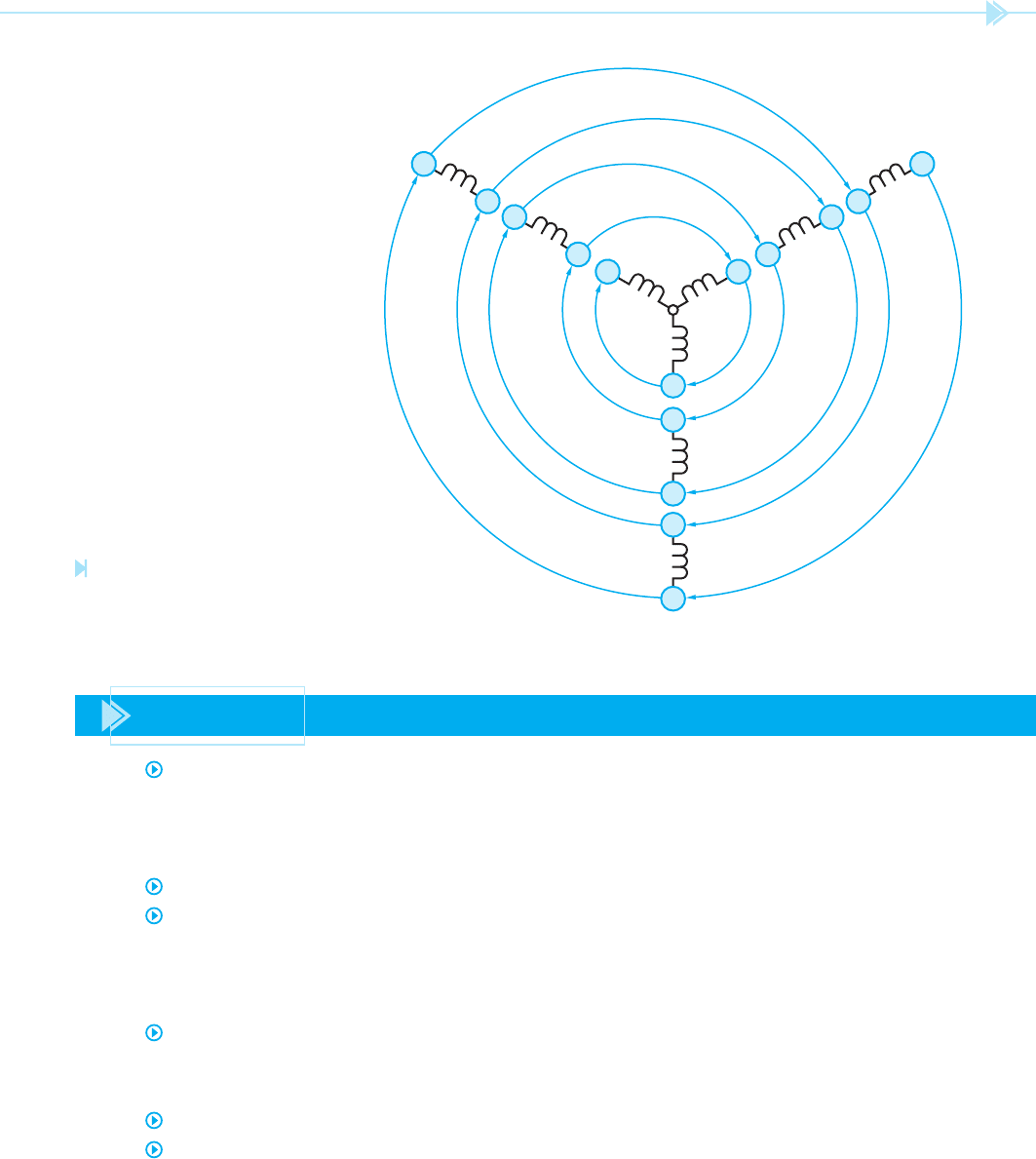
Many three-phase motors have dual-voltage sta-
tors. These stators are designed to be connected to
240 volts or 480 volts. The leads of a dual-voltage
stator use a standard numbering system. Figure 14–2
shows a dual-voltage wye-connected stator. Notice
the stator leads have been numbered in a spiral. This
diagram shows that numbers 1 and 4 are opposite
ends of the same coil. Lead number 7 begins another
coil, and this coil is to be connected to the same
phase as 1 and 4. Leads 2 and 5 are opposite ends
of the same coil. Coil number 8 must be connected
with the same phase as leads 2 and 5. Leads 3 and
6 are opposite ends of a coil and must be connected
with lead number 9. Keep in mind that Figure 14–2
8
2
5
3
6
9
7
4
1
Figure 14–2
Numbering a dual-voltage stator. (Source: Delmar/Cengage
Learning)
3
4
1
6
9
7
8
5
2
Figure 14–3
Leads of a dual-voltage motor.
(Source: Delmar/Cengage Learning)

154 SECTION 3 Motors
the schematic equivalent of this connection. Notice
that the windings have been connected in series.
Figure 14–6 shows the stator connection for opera-
tion on a 240-volt line. Figure 14–7 shows the
schematic equivalent of this connection. When
the motor is to be operated on 240 volts, the stator
windings are connected in parallel. Notice that leads
4, 5, and 6 are connected together to form another
center point. This centerpoint is electrically the same
as the point where leads 7, 8, and 9 join together.
Figure 14–8 shows the equivalent circuit.
L
1
1
4
7
L
2
2
5
8
L
3
3
6
9
Figure 14–4
High-voltage connection. (Source: Delmar/Cengage Learning)
8
2
5
3
6
9
7
4
1
Figure 14–5
Windings connected in series. (Source: Delmar/Cengage Learning)
L
1
1
4
7
L
2
2
5
8
L
3
3
6
9
Figure 14–6
Low-voltage connection. (Source: Delmar/Cengage Learning)
8
2
5
3
L
3
L
1
L
2
6
9
7
4
1
Figure 14–7
Windings connected in parallel.
(Source: Delmar/Cengage Learning)
When a motor is operated on a 240-volt line,
the current draw of the motor is double the current
draw of a 480-volt connection. For example, if a
motor draws 10 amps of current when connected
to 240 volts, it will draw 5 amps when connected
to 480 volts. The reason for this is the difference of
impedance in the windings between a 240-volt con-
nection and a 480-volt connection. For instance,
assume the stator windings of a motor have an
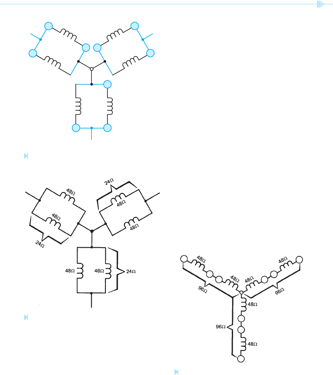
UNIT 14 Three-Phase Motor Principles 155
Rt ⫽
48 ⫻ 48
________
48 ⫹ 48
Rt ⫽
2304
_____
96
Rt ⫽ 24 ohms
If 240 volts is applied to this connection, 10 amps of
current will ow.
I ⫽
E
__
R
I ⫽
240
____
24
I ⫽ 10 amps
If the windings are connected in series for operation
on a 480-volt line as shown in Figure 14–10, the
total impedance of the winding is 96 ohms.
Rt ⫽ R1 ⫹ R2
Rt ⫽ 48 ⫹ 48
Rt ⫽ 96 ohms
If 480 volts is applied to this winding, 5 amps of
current will ow.
I ⫽
E
__
R
I ⫽
480
____
96
I ⫽ 5 amps
8 2
5
L
2
L
3
L
1
6
9
3
4
1
7
Figure 14–8
Equivalent parallel circuit. (Source: Delmar/Cengage Learning)
Figure 14–9
Total impedance of a parallel connection.
(Source: Delmar/
Cengage Learning)
impedance of 48 ohms. If the stator windings are
connected in parallel as shown in Figure 14–9, the
total impedance of the windings is 24 ohms.
Rt ⫽
R1 ⫻ R2
________
R1 ⫹ R2
Figure 14–10
Impedance adds in series. (Source: Delmar/Cengage Learning)
156 SECTION 3 Motors
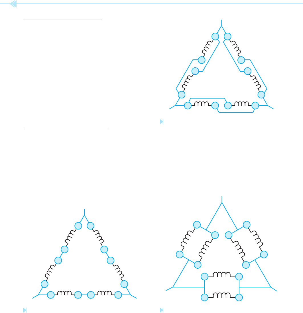
DELTA CONNECTIONS
Three-phase motors are also connected in delta. The
same standard numbering system is used for delta-
connected motors. If a dual-voltage motor is to be
connected in delta, there must be 12 leads instead of
9 leads brought out at the terminal box.
Figure 14–11 shows the schematic diagram of
a motor connected for operation as a high-voltage
delta. Notice that the stator windings for each phase
have been connected in series for operation on high
voltage. If the motor is to be connected for operation
on a low voltage, the windings will be connected in
parallel as shown in Figure 14–12. Figure 14–13
shows an equivalent parallel connection.
SPECIAL CONNECTIONS
Some three-phase motors designed for operation on
voltages higher than 600 volts may have more than
9 or 12 leads brought out at the terminal box. A motor
with 15 or 18 leads can be found in high-voltage
installations. A 15-lead motor has 3 coils per phase
instead of 2. Figure 14–14 shows the proper number
sequence for a 15-lead motor. Notice the leads are
numbered in the same spiral as a 9-lead motor.
811 25
L
3
L
2
L
1
310
6
7
94
12 1
Figure 14–11
High-voltage delta connection. (Source: Delmar/Cengage Learning)
811 25
310
6
7
94
12 1
Figure 14–12
Low-voltage delta connection. (Source: Delmar/Cengage Learning)
2
8
11
5
9
12
7
1
10
4
6
3
Figure 14–13
Equivalent parallel delta connection. (Source: Delmar/Cengage
Learning)
UNIT 14 Three-Phase Motor Principles 157
14
8
11
2
5
13
10
7
4
1
15
12
9
6
3
Figure 14–14
Fifteen-lead motor.
(Source: Delmar/Cengage Learning)
SUMMARY
The three basic types of three-phase motors are:
A. Squirrel-cage induction.
B. Wound rotor induction.
C. Synchronous.
All three-phase motors operate on the principle of a rotating magnetic eld.
Three factors that cause a magnetic eld to rotate are:
A. The voltages of a three-phase system are 120° out of phase with each other.
B. The three voltages change polarity at regular intervals.
C. The arrangement of the stator winding around the inside of the motor.
The speed of the rotating magnetic eld is determined by two factors:
A. The number of stator poles.
B. The frequency of the applied voltage.
The ends of the stator windings are numbered in a standard manner.
The stator windings of some three-phase motors are connected in a wye con guration and
some are connected in a delta con guration.

158 SECTION 3 Motors
When a dual-voltage motor is to be connected for operation at low voltage, the stator
windings will be connected in parallel.
When a dual-voltage motor is to be connected for operation on high voltage, the stator
windings will be connected in series.
KEY TERMS
rotating magnetic eld
synchronous speed
three-phase motors
REVIEW QUESTIONS
1. What are the three basic types of three-phase motors?
2. Name three factors that produce a rotating magnetic eld.
3. What is synchronous speed?
4. What two factors determine the synchronous speed of a three-phase motor?
5. How is the direction of rotation of a three-phase motor changed?
6. What is the synchronous speed of a four-pole motor when connected to a
60-Hz line?
7. A dual-voltage three-phase motor has a current draw of 50 amps when connected to
a 240-volt line. How much current will ow if the motor is connected for operation
on 480 volts?
8. If the stator windings of a three-phase motor are connected for operation on high
voltage, will the windings be connected in series or parallel?
9. If a dual-voltage motor is connected for operation on low voltage, and the motor is
then connected to high voltage, will the motor operate at a faster speed?
10. Why does a dual-voltage motor draw more current when connected to low voltage
than it does when connected to high voltage?

159
The squirrel-cage induction motor receives
its name from the fact that the rotor contains a set
of bars that resemble a squirrel cage. If the soft-iron
laminations were to be removed from the rotor,
it would be seen that the rotor contains a set of
metal bars joined together at each end by a metal
ring, Figure 15–1. Figure 15–2 shows a complete
squirrel-cage rotor and stator winding.
PRINCIPLE OF OPERATION
The squirrel-cage motor is an induction motor. This
means that the current ow in the rotor is produced
by induced voltage from the rotating magnetic eld
of the stator. In Figure 15–3, a squirrel-cage rotor
is shown inside the stator winding of a three-phase
motor. It will be assumed that the motor shown in
Figure 15–3 contains four poles per phase, which
The
Squirrel-Cage
Induction
Motor
UNIT 15
OBJECTIVES
After studying this unit the student should
be able to:
Discuss the principle of operation
of a squirrel-cage three-phase motor
List the factors that determine the
amount of torque developed by
a squirrel-cage motor
Discuss code letters and their meaning
Perform an ohmmeter test on a three-
phase squirrel-cage motor