Stephen L. Herman, Bennie Sparkman. Electricity and Controls for HVAC-R (6th edition)
Подождите немного. Документ загружается.

180 SECTION 3 Motors
wound rotor motor is that it limits the amount of
inrush current when the motor is rst started. This
eliminates the need for reduced voltage starters or
wye-delta starting.
Another advantage of the wound rotor motor is
its high starting torque. Because resistors are used
to limit current ow in the rotor, the phase angle
between the stator current and the rotor current
is close to 90°. The schematic symbol for a wound
rotor motor is shown in Figure 16–4.
MOTOR OPERATION
When power is applied to the stator winding, a rotat-
ing magnetic eld is created in the motor. This mag-
netic eld cuts through the windings of the rotor and
induces a voltage into them. The amount of voltage
induced in the rotor windings is determined by the
same three factors that determined the amount
of voltage induced in the squirrel-cage rotor. The
amount of current ow in the rotor is determined by
the amount of induced voltage and the amount of
resistance connected to the rotor (I ⫽ E/R). When
current ows through the rotor, a magnetic eld
is produced. This magnetic eld is attracted to the
rotating magnetic eld of the stator.
As the rotor speed increases, the induced voltage
decreases because of less cutting action between
the rotor windings and rotating magnetic eld.
This produces less current ow in the rotor and,
therefore, less torque. If resistance is reduced, more
current can ow, which will increase motor torque,
and the rotor will increase in speed. This action
continues until the rotor is operating at maximum
speed and all resistance has been shorted out of the
rotor circuit. When all of the resistance has been
a schematic diagram of the stator connection and
rotor connection of a wound rotor motor. Notice
that the wye-connected stator winding is connected
directly to the incoming power. The wye-connected
rotor is connected to three variable resistors. The
dashed line drawn between the resistors indicates
that they are mechanically connected together. If
the resistance of one is changed, the resistance of
the other two changes also.
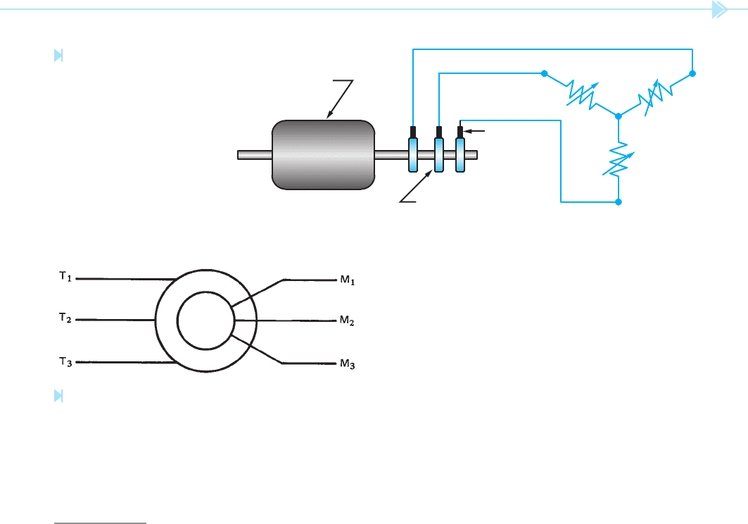
Resistance is connected to the slip rings by means
of
carbon brushes as shown in Figure 16–3.
Because the resistance connection to the rotor is
external, the amount of resistance used in the cir-
cuit can be controlled. This permits the amount
of current
ow in the rotor to be controlled. If the
current ow in the rotor is limited by the amount
of resistance connected in the circuit, the stator
current is limited also. A great advantage of the
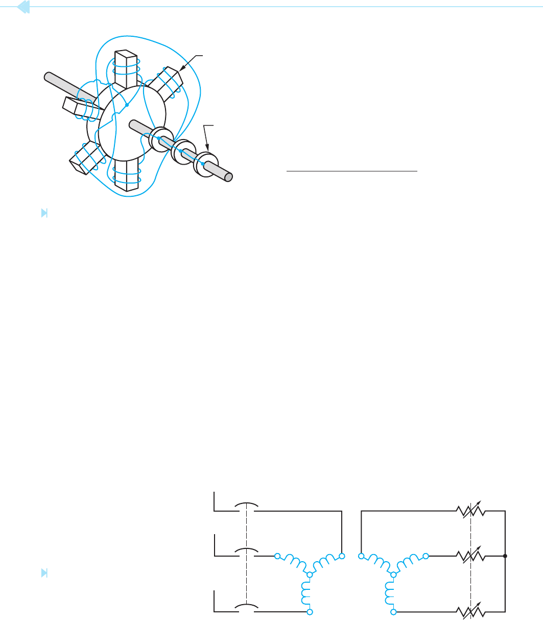
Figure 16–1
A wound rotor. (Source: Delmar/Cengage Learning)
POLE PIECE
SLIP RING
STATOR ROTOR
L
2
L
1
L
3
Figure 16–2
A wye-connected stator and
wye-connected rotor.
(Source: Delmar/Cengage Learning)
UNIT 16 The Wound Rotor Induction Motor 181
current ow to the stator. This method is known
as current limit control. Another method detects
the speed of the rotor. This method is known as
slip frequency control. One of the most common
methods uses time relays to control when resistance
is shorted out of the circuit. This method is known
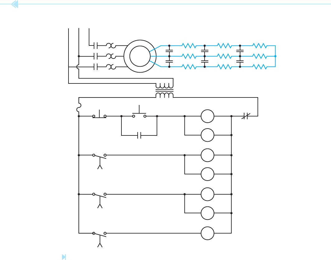
as de nite time control. Figure 16–5 shows a
schematic diagram of a time-controlled starter for
a wound rotor motor. In this schematic, the motor
circuit is shown at the top of the diagram. A control
transformer is used to step the line voltage down to
the value of voltage used in the control circuit. The
operation of the circuit is as follows:
1. When the start button is pressed, a circuit
is completed through M motor starter coil,
TR1 coil, and the overload contact. When M
coil energizes, all M contacts close. The three
large load contacts located at the top of the
diagram close and connect the stator winding
to the line. The M contact located beneath
the start button is known as the holding,
sealing, or maintaining contact. Its
job is to provide a continued circuit to the M
coil when the start button is released. The
motor now begins to run in its lowest speed.
Maximum resistance is connected in the
rotor circuit.
2. TR1 relay is a timer. For this example, it shall
be assumed that all timers are set for a delay
of 3 seconds. When TR1 coil energizes, it
begins a time operation. After 3 seconds, TR1
contact closes. This completes a circuit to S1
coil and TR2 coil.
shorted out, the motor operates like a squirrel-cage
induction motor.
STARTING
Most large wound rotor motors use a method of
step starting as opposed to actual variable resis-
tors. Step starting is similar to shifting the gears
in the transmission of an automobile. The trans-
mission is placed in rst gear when the car is rst
started. As the car gains speed, the transmission is
shifted to second gear, then third gear, and so on
until the car is operating in its highest gear. When
a wound rotor motor is step started, it begins with
maximum resistance connected in the rotor circuit.
As the motor speed increases, resistance is shorted
out of the circuit until the windings of the rotor are
shorted together. The number of steps can vary from
one motor to another, depending on the size of the
motor and how smooth a starting action is desired.
There are different control methods used to short
out the steps of resistance when starting a wound
rotor motor. Some controllers sense the amount of
Wound Rotor
Slip Rings
Brushes
External Resistors
Figure 16–3
External resistance is con-
nected to the rotor circuit
with brushes and slip rings.
(Source: Delmar/Cengage Learning)
Figure 16–4
Schematic symbol of a wound rotor induction motor.
(Source: Delmar/Cengage Learning)
182 SECTION 3 Motors
6. After a 3-second time period, contact TR3
closes and provides a complete circuit for coil
S3. This causes both S3 contacts to close and
short out the last set of resistors. The motor
now accelerates to its highest speed.
7. When the stop button is pressed, the circuit
to coil M and coil TR1 is broken. When coil M
deenergizes, all M contacts open. This discon-
nects the stator winding from the line. When
TR1 coil deenergizes, contact TR1 opens
immediately. This deenergizes coil S1 and
coil TR2. When coil S1 deenergizes, both S1
contacts return to their open position.
3. When S1 coil energizes, both S1 contacts
close and short out the last three resistors in
the rotor circuit. This causes the motor to
accelerate to the next higher speed. When
TR2 coil energizes, it begins timing.
4. At the end of a 3-second time period, TR2
contact closes and completes a circuit to coil
S2 and TR3.
5. When S2 coil energizes, both S2 contacts
close and short out the next set of resistors.
This permits the motor to accelerate to a
higher speed. When TR3 coil energizes, it
begins its timing sequence.
T
3
T
2
T
1
L
1
L
2
L
3
M
3
M
S
3
S
2
S
1
M
2
M
1
S
3
S
2
S
1
M
M
CONTROL
TRANSFORMER
OL
M
TR
1
S
1
TR
2
S
2
TR
3
S
3
M
START
STOP
FUSE
TR
1
TR
2
TR
3
Figure 16–5
Defi nite time starting for a wound rotor motor. (Source: Delmar/Cengage Learning)
UNIT 16 The Wound Rotor Induction Motor 183
When coil TR1 deenergizes, contact TR2
opens immediately. When contact TR2
opens, it breaks the circuit to coil S2 and coil
TR3. When coil S2 deenergizes, both S2 con-
tacts reopen. Contact TR3 opens immediately
when coil TR3 deenergizes. This causes coil
S3 to deenergize and open both S3 contacts.
8. If the fuse should blow, or the overload con-
tact open, it has the same effect as pressing
the stop button.
TESTING A WOUND ROTOR
MOTOR
Because the stator winding of the wound rotor
motor is the same as the squirrel-cage motor, the
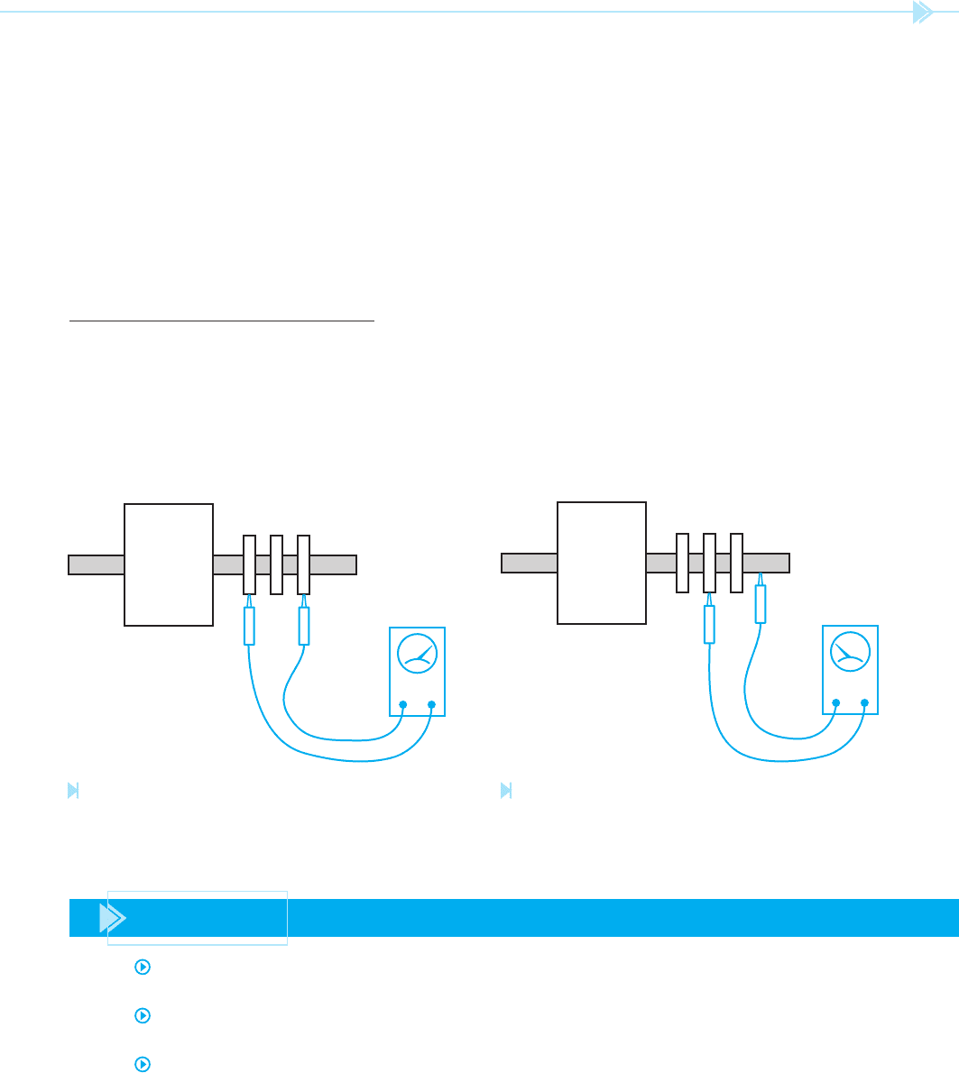
OHMMETER
Figure 16–6
Testing a rotor for an open winding. (Source: Delmar/Cengage
Learning)
OHMMETER
Figure 16–7
Testing a rotor for a grounded winding. (Source: Delmar/
Cengage Learning)
same test procedure can be followed. Testing the
rotor of a wound rotor motor is very similar to test-
ing the stator. The rotor can be tested for an open
winding with an ohmmeter by checking the conti-
nuity between each of the slip rings, Figure 16–6.
The resistance readings should be the same between
each pair of slip rings. To test the rotor for a ground,
connect one ohmmeter lead to the shaft, and con-
nect the other lead to each one of the slip rings,
Figure 16–7. The ohmmeter should show no conti-
nuity between the rotor windings and ground. Like
the stator winding, the rotor is dif cult to test for
a shorted winding. To test the rotor for a shorted
winding it is generally necessary to use equipment
that will measure the inductance of the winding
instead of its resistance.
SUMMARY
The stator winding of a wound rotor induction motor is the same as the stator winding of
a squirrel-cage induction motor.
The rotor of a wound rotor induction motor contains windings instead of squirrel-cage
bars.
The rotor of a wound rotor induction motor will contain as many poles per phase as the
stator winding.

184 SECTION 3 Motors
The nish ends of each winding of a wound rotor are connected together to form a wye
connection and the other ends of each winding are connected to a slip ring on the shaft.
Wound rotor induction motors are sometimes called slip ring motors because they contain
three slip rings on their shaft.
Wound rotor induction motors have a higher starting torque per amp of starting current
than any other type of three-phase motor.
The speed of a wound rotor induction motor can be controlled by permitting resistance to
remain in the rotor circuit during operation.
The brushes of a wound rotor induction motor are used to provide connection of the rotor
windings to external resistors.
The stator winding leads of a wound rotor induction motor are labeled T
1
, T
2
, and T
3
.
The rotor leads of a wound rotor induction motor are labeled M
1
, M
2
, and M
3
.
KEY TERMS
REVIEW QUESTIONS
1. How many slip rings are located on the shaft of the rotor of a wound rotor induction
motor?
2. What is the purpose of the slip rings?
3. Name two advantages of the wound rotor motor over the squirrel-cage motor.
4. What two factors determine the amount of current ow in the rotor of a wound rotor
motor?
5. What does the dashed line drawn between the three resistors shown in Figure 16–2
indicate?
6. Why is the starting torque of a wound rotor induction motor higher than the starting
torque of a squirrel-cage induction motor?
7. The stator of a wound rotor motor has a synchronous speed of 1,200 RPM when
connected to a 60-Hz line. How many poles per phase are there in the rotor?
8. Refer to Figure 16–5. Describe what would happen in this circuit if coil S1 should be
open when the motor started.
9. Refer to Figure 16–5. Describe what would happen in this circuit if coil TR2 should be
open when the motor is started.
10. Refer to Figure 16–5. Describe what would happen in this circuit if holding contact M
should become stuck together when the motor is started and not open.
carbon brushes
de nite time control
holding, sealing, or
maintaining contact
slip ring
step starting
wound rotor induction
motor

UNIT 16 The Wound Rotor Induction Motor 185
TROUBLESHOOTING QUESTIONS
Refer to the schematic shown in Figure 16–5 to answer the following questions. It is to be assumed
that all timers are set for a delay of 3 seconds.
1. When the start button is pressed, the motor starts in its lowest speed. After a delay of
6 seconds, the motor accelerates to third speed and 3 seconds later accelerates to the
fourth or highest speed. Which of the following could cause this problem?
A. Coil TR
1
is open.
B. Timed contact TR
1
did not close.
C. Coil S
1
is open.
D. Coil TR
2
is open.
2. When the start button is pressed, the motor starts and accelerates through all speeds
normally. When the stop button is pressed, the motor continues to operate normally.
Which of the following could cause this condition?
A. The start button is shorted. (Shorted means contacts welded together.)
B. The stop button is shorted.
C. M auxiliary contact is shorted.
D. Any of the above.
3. When the start button is pressed, the motor accelerates through the rst three steps of
speed normally. When the motor tries to accelerate to the fourth speed, however, the
motor stops. It is found that the control circuit fuse has blown. Which of the following
conditions could cause this problem?
A. The overload (OL) contact has shorted.
B. Coil S
2
is shorted.
C. Coil TR
3
is shorted.
D. Coil S
3
is shorted.
4. When the start button is pressed, the motor immediately starts operating in third speed.
Three seconds later, the motor accelerates to fourth speed. Which of the following could
cause this condition?
A. TR
2
timed contact is shorted.
B. TR
3
timed contact is shorted.
C. S
2
load contacts are shorted.
D. None of the above.
5. When the start button is pressed, the motor will not start. Which of the following could
cause this condition?
A. The control transformer is defective.
B. The control circuit fuse is blown.
C. The overload contact is open.
D. All of the above.

The third type of three-phase motor to be discussed is
the synchronous motor. This motor has several
characteristics that no other type of motor has. Some
of the characteristics of a synchronous motor are:
1. The synchronous motor is not an induction
motor. This means that it does not depend on
induced voltage from the stator to produce a
magnetic eld in the rotor.
2. The synchronous motor will run at a con-
stant speed from no load to full load.
3. The synchronous motor has the ability to not
only correct its own power factor, but can
also correct the power factor of other motors
connected to the same line.
The synchronous motor has the same type
of stator windings as the other two three-phase
motors. The rotor of a synchronous motor has
The
Synchronous
Motor
OBJECTIVES
After studying this unit the student should
be able to:
Describe the construction of a
synchronous motor
Compare the operating characteristics
of a synchronous motor with those of a
squirrel-cage induction motor and
a wound rotor induction motor
Discuss the starting and running
characteristics of a synchronous motor
Describe the function of the fi eld
discharge resistor
Discuss power factor correction using
the synchronous motor
Perform an ohmmeter test of
a synchronous motor
186
UNIT 17
UNIT 17 The Synchronous Motor 187
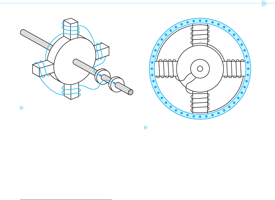
slip rings on the rotor shaft, Figure 17–3. When
DC is applied to the rotor, the windings on the rotor
become electromagnets. The electromagnetic
eld of the rotor locks in step with the rotating
magnetic eld of the stator. The rotor will now turn
at the same speed as the rotating magnetic eld.
When the rotor begins to turn at the synchronous
speed of the eld, there is no more cutting action
between the eld and the amortisseur winding. This
causes the current ow in the amortisseur winding
to cease.
Notice that the synchronous motor starts as a
squirrel-cage induction motor. Because the rotor
bars used are type “A,” they have a relatively high
resistance, which gives the motor good starting
torque and low starting current. A synchronous
motor must never be started with DC connected to
the rotor. If DC is applied to the rotor, the eld poles
of the rotor become electromagnets. When the sta-
tor is energized, the rotating magnetic eld begins
turning at synchronous speed. The electromagnets
of the rotor are attracted to the rotating magnetic
eld of the stator and are alternately attracted and
repelled 60 times a second. As a result, the rotor
does not turn.
windings similar to the wound rotor induction
motor, Figure 17–1. Notice that the winding in the
rotor of a synchronous motor is different, however.
The winding of a synchronous motor is one con-
tinuous set of coils instead of three different sets as
is the case with the wound rotor motor. Notice also
that the synchronous motor has only two slip rings
on its shaft as opposed to three on the shaft of a
wound rotor motor.
STARTING A SYNCHRONOUS
MOTOR
The rotor of a synchronous motor also contains
a set of type “A” squirrel-cage bars. This set of
squirrel-cage bars is used to start the motor and is
known as the amortisseur winding, Figure 17–2.
When power is rst connected to the stator, the
rotating magnetic eld cuts through the type “A”
squirrel-cage bars. The cutting action of the eld
induces a current into the squirrel-cage bars.
The current ow through the amortisseur winding
produces a rotor magnetic eld that is attracted to
the rotating magnetic eld of the stator. This causes
the rotor to begin turning in the direction of rotation
of the stator eld. When the rotor has accelerated
to a speed that is close to the synchronous speed of
the eld, DC is connected to the rotor through the
Figure 17–1
Rotor. (Source: Delmar/Cengage Learning)
Figure 17–2
Amortisseur winding. (Source: Delmar/Cengage Learning)
188 SECTION 3 Motors
does not depend on induced voltage from the stator
eld to produce a magnetic eld in the rotor. The
magnetic eld of the rotor is produced by external
DC applied to the rotor. This is the reason that the
synchronous motor has the ability to operate at the
speed of the rotating magnetic eld. As load is added
to the motor, the magnetic eld of the rotor remains
locked with the rotating magnetic eld and the rotor
continues to turn at the same speed.
POWER FACTOR CORRECTION
The power factor of the synchronous motor can be
changed by adjusting the DC excitation cur-
rent to the rotor. When the DC is adjusted to the
point that the motor current is in phase with the
voltage, the motor has a power factor of 100%. This
is considered to be normal excitation for the motor.
For this example, assume this current to be 10 amps.
If the DC power supply is adjusted to a point that the
excitation current is less than 10 amps, the rotor
is under excited. This causes the motor to have a
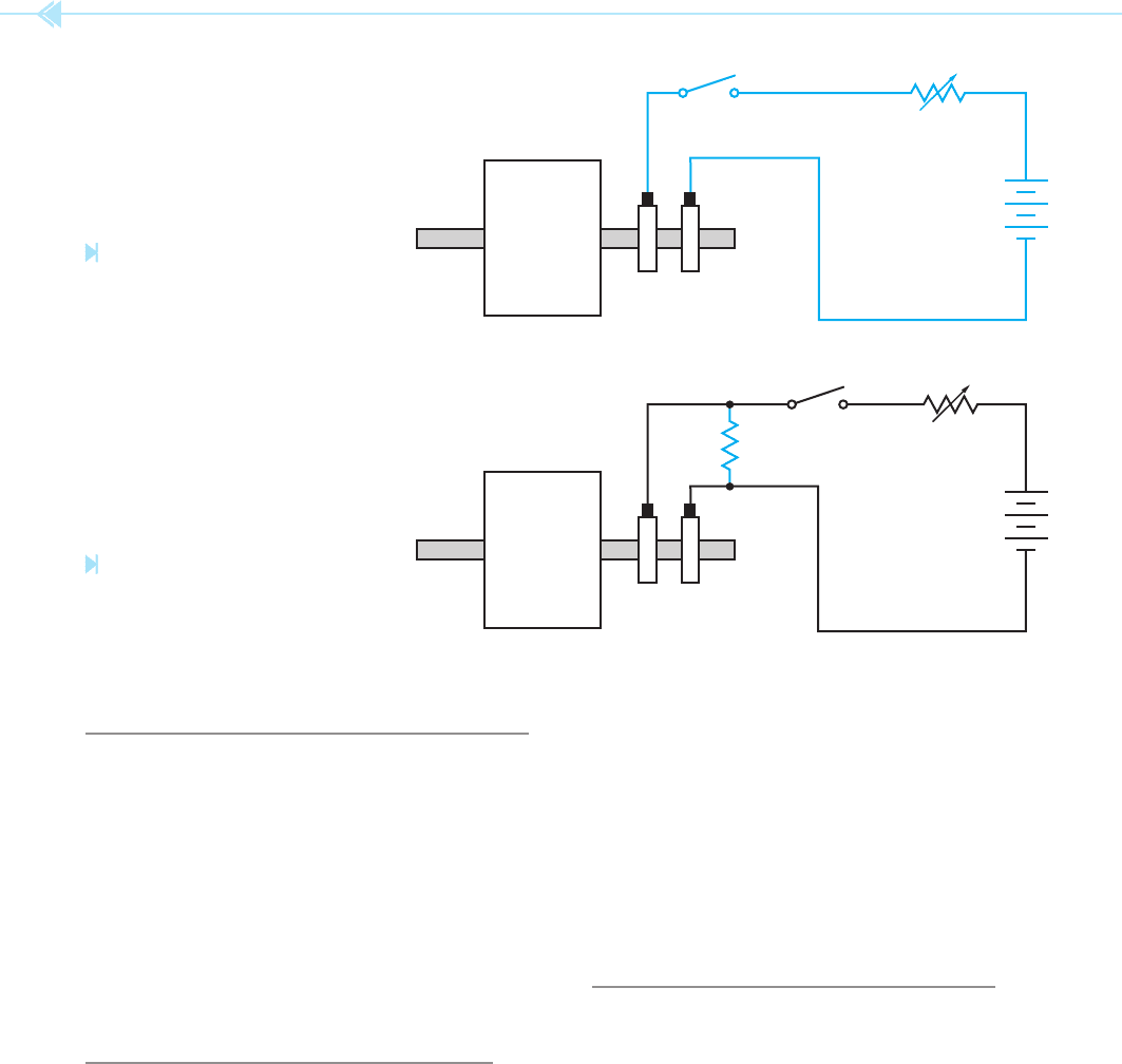
THE FIELD DISCHARGE RESISTOR
When the stator winding is rst energized, the rotat-
ing magnetic eld cuts through the rotor winding at
a fast rate of speed. This causes a large amount of
voltage to be induced into the winding of the rotor.
To prevent this voltage from becoming excessive, a
resistor is connected across the winding. This resis-
tor is known as the eld discharge resistor,
Figure 17–4. It also helps to reduce the voltage
induced into the rotor by the collapsing magnetic
eld when the DC is disconnected from the rotor.
CONSTANT SPEED OPERATION
Although the synchronous motor starts as an
induction motor, it does not operate as one. After
the amortisseur winding has been used to accelerate
the rotor to about 95% of the speed of the rotating
magnetic eld, direct current is connected to the
rotor and the electromagnets lock in step with the
rotating eld. Notice that the synchronous motor
+
Figure 17–3
Direct current is applied to the
rotor through the slip rings.
(Source: Delmar/Cengage Learning)
FIELD DISCHARGE RESISTOR
+
Figure 17–4
A fi eld discharge resistor protects
the rotor circuit. (Source: Delmar/Cengage
Learning)
UNIT 17 The Synchronous Motor 189
the ohmmeter. In coils designed for DC current,
the resistance of the wire is used to limit the ow
of current. For example, assume the speci ca-
tions of a synchronous motor indicate that the DC
excitation voltage should be 125 volts, and that
maximum rotor current should be 10 amps. The
resistance of the rotor can now be calculated by
using Ohm’s law:
R
E
__
I
R
125
____
10
R 12.5 ohms
If the ohmmeter measures a rotor resistance close
to 12.5 ohms, the rotor is good. If the ohmmeter
measures a much lower resistance, however, the
rotor is shorted.
lagging power factor like an induction motor. If the
excitation current is adjusted above 10 amps, the
rotor is overexcited. This causes the motor to have
a leading power factor like a capacitor. When a syn-
chronous motor is operated at no load and used for
power factor correction, it is generally referred to as
a synchronous condenser. Utility companies
generally charge industries extra for poor power
factor in the plant. For this reason, synchronous
motors are often used when a large horsepower
motor must be used. Commercial and industrial air
conditioning systems are often the largest single
load in a plant or building. It is not uncommon to
nd synchronous motors being used to operate the
compressors of large air-conditioning systems.
THE POWER SUPPLY
DC power supply of a synchronous motor can be pro-
vided by several methods. The most common of these
methods is either a small DC generator mounted to
the shaft of the motor, or an electronic power supply
that converts the AC line voltage to DC voltage.
TESTING THE SYNCHRONOUS
MOTOR
The procedure for testing the stator winding of a
synchronous motor is the same as that described
for testing the stator of a squirrel-cage induction
motor. The rotor can be tested with an ohmmeter
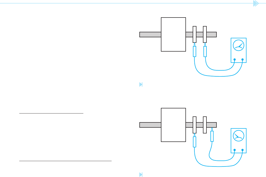
for an open winding or a grounded winding. To
test the rotor for an open winding, connect one of
the ohmmeter leads to each of the slip rings on the
rotor shaft, Figure 17–5. Since the rotor winding of
a synchronous motor is intended for DC current, the
resistance of the wire will be high as compared with
the wire resistance of a wound rotor motor. Owing
to the fact that alternating current ows in the rotor
of a wound rotor motor, the current is limited by the
inductance of the coil and not its resistance.
To test the rotor for a grounded winding, connect
one ohmmeter lead to the shaft of the motor, and the
other lead to one of the slip rings. There should be
no continuity between the winding and the motor
shaft, Figure 17–6.
Because the resistance of the rotor is relatively
high, a shorted winding can often be found with
Figure 17–5
Testing the rotor for an open winding.
(Source: Delmar/Cengage
Learning)
Figure 17–6
Testing the rotor for a grounded winding. (Source: Delmar/
Cengage Learning)