Stephen L. Herman, Bennie Sparkman. Electricity and Controls for HVAC-R (6th edition)
Подождите немного. Документ загружается.

210 SECTION 4 Transformers
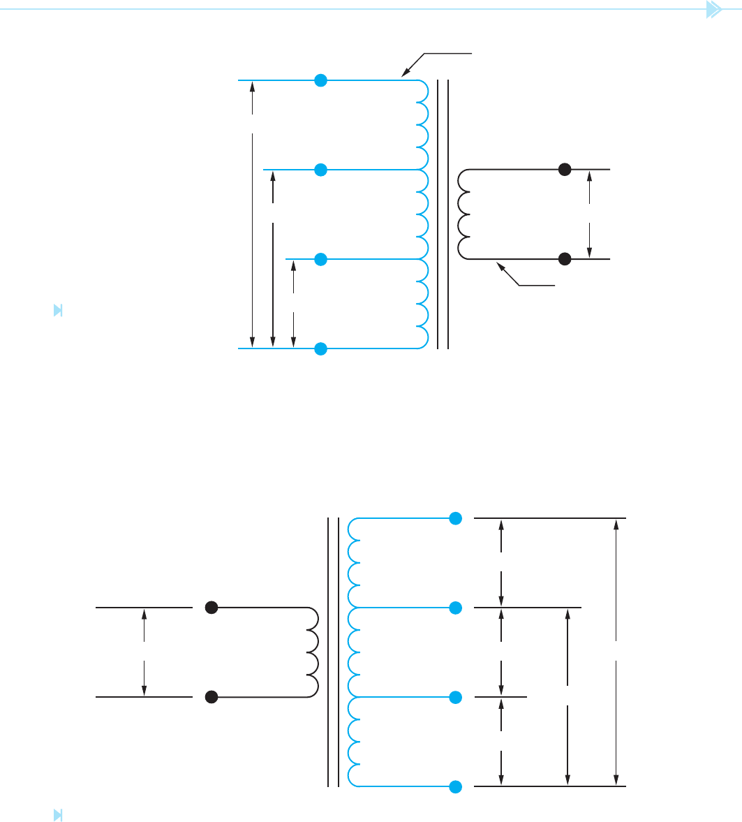
designed in such a manner that it can be connected
to different primary voltages without changing the
value of the secondary voltage. In this example, it
is assumed that the secondary winding has a total
of 120 turns of wire. To maintain the proper turns
ratio, the primary would have 600 turns of wire
between C and 120; 1,040 turns between C and
208; and 1,200 turns between C and 240.
The transformer shown in Figure 19–19 contains
a single primary winding. The secondary winding,
however, has been tapped at several points. One of
the secondary lead wires is labeled C and is com-
mon to the other lead wires. When rated voltage
is applied to the primary, voltages of 12, 24, and
48 volts can be obtained at the secondary. It should
also be noted that this arrangement of taps permits
the transformer to be used as a center tapped trans-
former for two of the voltages. If a load is placed
across the lead wires labeled C and 24, the lead wire
labeled 12 becomes a center tap. If a load is placed
across the C and 48 lead wires, the 24-lead wire
becomes a center tap.
In this example, it is assumed the primary wind-
ing has 300 turns of wire. In order to produce the
proper turns ratio, it would require 30 turns of wire
between C and 12, 60 turns of wire between C and
24, and 120 turns of wire between C and 48.
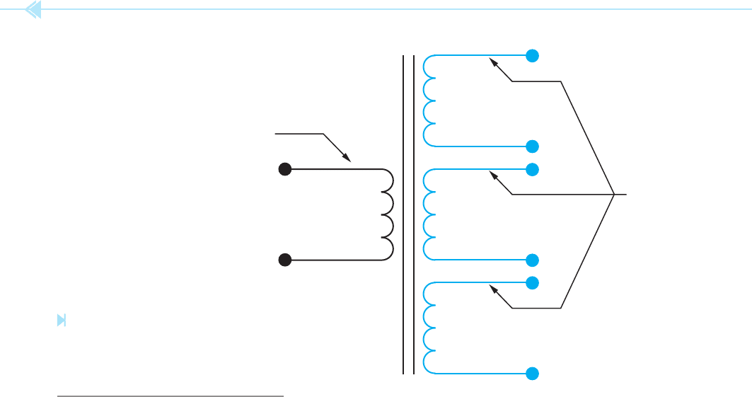
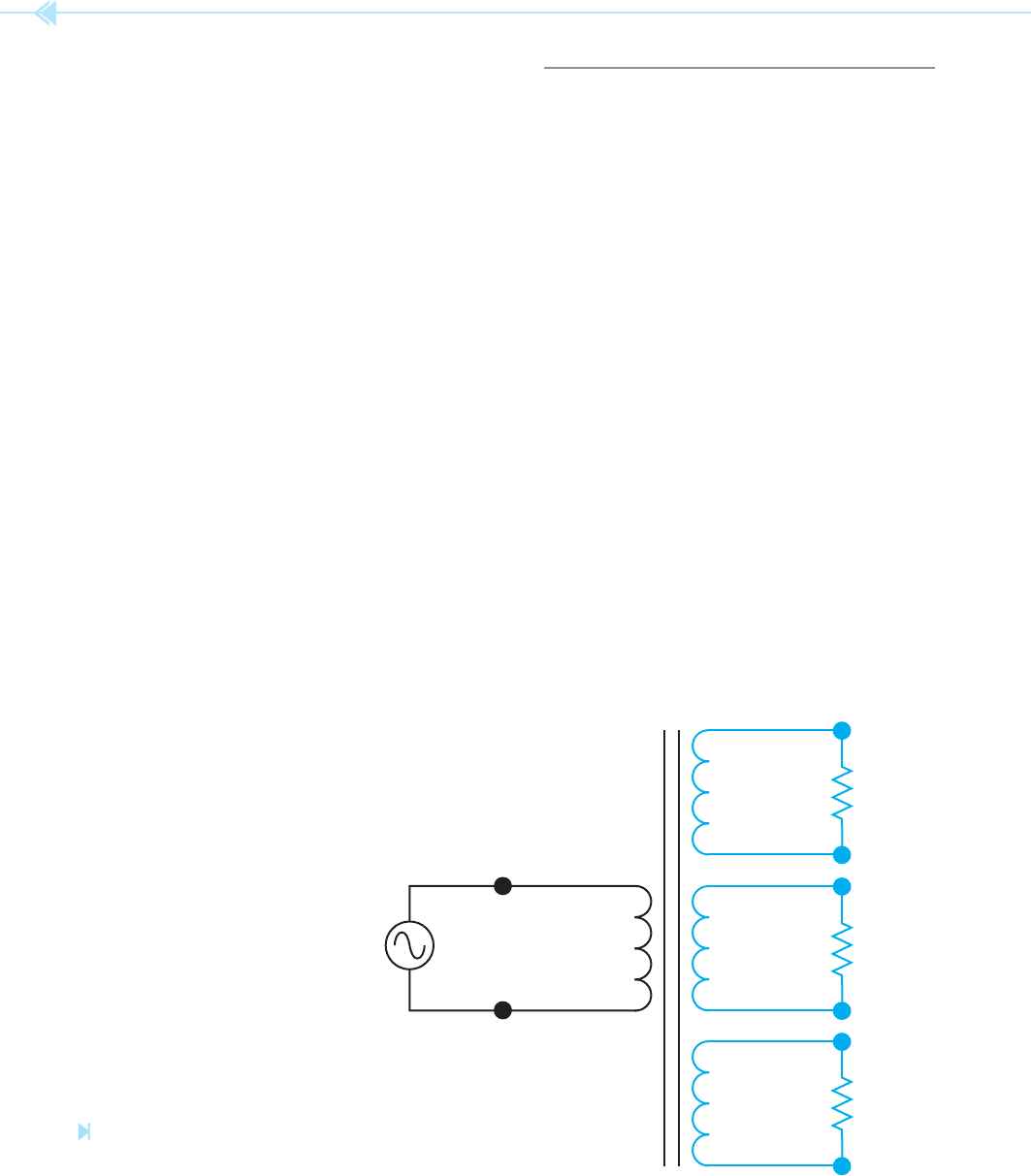
The transformer shown in Figure 19–20 is similar
to the transformer in Figure 19–19. The transformer
in Figure 19–20, however, has multiple secondary
windings instead of a single secondary winding with
multiple taps. The advantage of the transformer in
Figure 19–20 is that the secondary windings are
electrically isolated from each other. These secondary
windings can be either step-up or step-down depend-
ing on the application of the transformer.
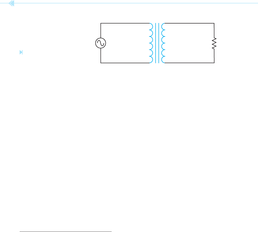
To check this answer, compute the volt amps of
both windings.
Primary
120 1.74 208.8
Secondary
500 0.417 208.8
The slight difference in answers is caused by round-
ing off the values.
Because the primary voltage is less than the
secondary voltage, the turns of wire in the primary
will be less also. The primary turns will be found by
dividing the turns of wire in the secondary by the
turns ratio.
N
P
N
S
__________
Turns Ratio
N
P
800
_____
4.17
N
P
192 turns
Figure 19–17 shows the transformer with all
completed values.
MULTIPLE TAPPED WINDINGS
It is not uncommon for transformers to be designed
with windings that have more than one set of lead
wires connected to the primary or secondary. The
transformer shown in Figure 19–18 contains a
secondary winding rated at 24 volts. The primary
winding contains several taps, however. One of the
primary lead wires is labeled C and is the common
for the other leads. The other leads are labeled 120,
208, and 240, respectively. This transformer is
E
S
500
I
S
0.417
N
S
800
E
P
120
I
P
1.74
N
P
192
Z = 1-200Ω
RATIO: 1:4.17
Figure 19–17
Transformer with completed
values. (Source: Delmar/Cengage Learning)
UNIT 19 Isolation Transformers 211
24 V 120 TURNS
240V
208V
120V
C
1200 TURNS
1040 TURNS
600 TURNS
PRIMARY WINDING
SECONDARY WINDING
Figure 19–18
Transformer with multiple
tap primary winding.
(Source:
Delmar/Cengage Learning)
120V300 TURNS
48V
24V
12V
C
120 TURNS
60 TURNS
30 TURNS
30 TURNS
60 TURNS
Figure 19–19
Transformer secondary with multiple taps. (Source: Delmar/Cengage Learning)
212 SECTION 4 Transformers
The current ow in the rst secondary can be com-
puted using Ohm’s law.
I
S1
560
_____
1000
I
S1
0.56 amps
The number of turns of wire in the rst second-
ary winding will be found using the turns ratio.
Because this secondary has a higher voltage than
the primary, it must have more turns of wire. The
number of primary turns will be multiplied by the
turns ratio.
N
S1
N
P
Turns Ratio
N
S1
300 4.67
N
S1
1,401 turns
The amount of primary current needed to supply
this secondary winding can be found using the turns
ratio also. Because the primary has less voltage, it
will require more current. The primary current can
be determined by multiplying the secondary current
by the turns ratio.
I
P(FIRST SECONDARY)
I
S1
Turns Ratio
I
P(FIRST SECONDARY)
0.56 4.67
I
P(FIRST SECONDARY)
2.61 amps
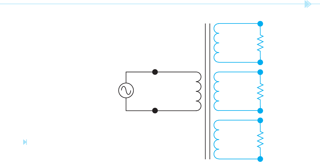
COMPUTING VALUES FOR
TRANSFORMERS WITH
MULTIPLE SECONDARIES
When computing the values of a transformer with
multiple secondary windings, each secondary must
be treated as a different transformer. For example, the
transformer in Figure 19–21 contains one primary
winding and three secondary windings. The primary
is connected to 120 volts AC and contains 300 turns
of wire. One secondary has an output voltage of
560 volts and a load impedance of 1,000 . The sec-
ond secondary has an output voltage of 208 volts and a
load impedance of 400 , and the third secondary has
an output voltage of 24 volts and a load impedance of
6 . The current, turns of wire, and ratio for each sec-
ondary and the current of the primary will be found.
SOLUTION: The fi rst step will be to compute the turns
ratio of the fi rst secondary. The turns ratio can be
found by dividing the smaller voltage into the larger.
Ratio
E
S1
___
E
P
Ratio
560
____
120
Ratio 1:4.67
PRIMARY
WINDING
SECONDARY
WINDINGS
Figure 19–20
Transformer with
multiple secondary
windings. (Source: Delmar/
Cengage Learning)
UNIT 19 Isolation Transformers 213
computed by multiplying the secondary current by
the turns ratio.
I
P(SECOND SECONDARY)
I
S2
Turns Ratio
I
P(SECOND SECONDARY)
0.52 1.732
I
P(SECOND SECONDARY)
0.9 amp
The turns ratio of the third secondary winding
will be computed in the same way as the other two.
The larger voltage will be divided by the smaller.
Ratio
120
____
24
Ratio 5:1
The primary current will be found using Ohm’s
law.
I
S3
24
___
6
I
S3
4 amps
Because the output voltage of the third secondary is
less than that of the primary, the number of turns
of wire for this secondary will be fewer than the pri-
mary turns. To nd the number of secondary turns,
divide the primary turns by the turns ratio.
N
S3
N
P
__________
Turns Ratio
The turns ratio of the second secondary winding
will be found by dividing the higher voltage by the
lower voltage.
Ratio
208
____
120
Ratio 1:1.73
The amount of current ow in this secondary can be
determined using Ohm’s law.
I
S2
208
____
400
I
S2
0.52 amp
Because the voltage of this secondary is greater
than the primary, it will have more turns of wire
than the primary. The turns of this secondary will
be found by multiplying the turns of the primary by
the turns ratio.
N
S2
N
P
Turns Ratio
N
S2
300 1.73
N
S2
519 turns
The voltage of the primary is less than this
secondary. The primary will, therefore, require a
greater amount of current. The amount of primary
current required to operate this secondary will be
E
S
1 = 560
I
S
1
N
S
1
RATIO
E
S
2 = 208
I
S
2
N
S
2
RATIO
Z
1
= 1,000 Ω
E
P
= 120
I
P
N
P
= 300T
Z
2
= 400 Ω
E
S
3 = 24
I
S
3
N
S
3
RATIO
Z
3
= 6 Ω
Figure 19–21
Computing values for a trans-
former with multiple secondary
windings. (Source: Delmar/Cengage Learning)
214 SECTION 4 Transformers
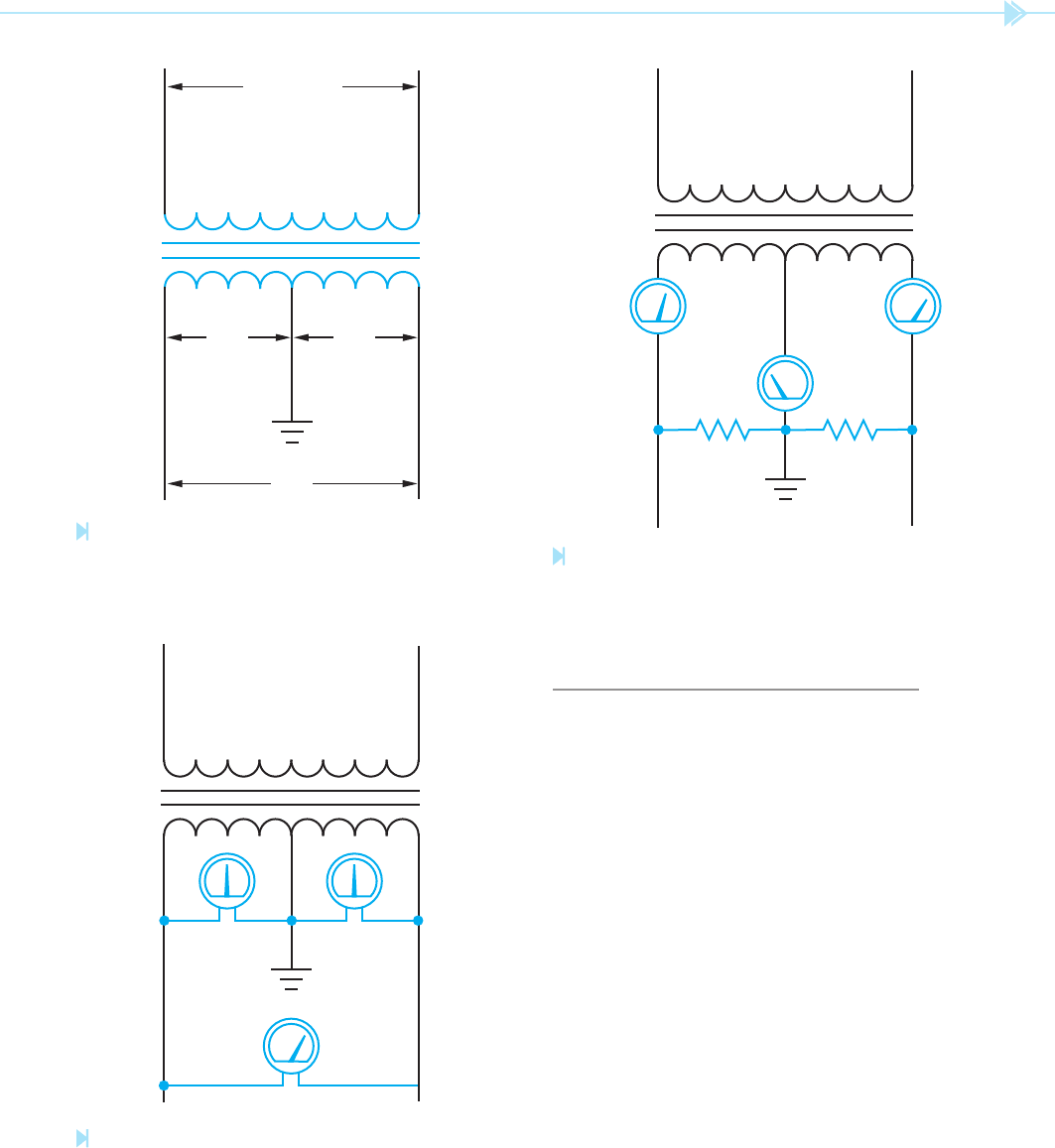
DISTRIBUTION TRANSFORMERS
A very common type of isolation transformer is the
distribution transformer, Figure 19–23. This trans-
former is used to supply power to most homes and
many businesses. In this example, it is assumed that
the primary is connected to a 7,200 volt line. The
secondary is 240 volts with a center tap. The center
tap is grounded and becomes the neutral conduc-
tor. If voltage is measured across the entire second-
ary, a voltage of 240 volts will be seen. If voltage is
measured from either line to the center tap, half of
the secondary voltage, or 120 volts, will be seen,
Figure 19–24. Loads that are intended to operate on
240 volts, such as water heaters, electric resistance
heating units, and central air conditioners are con-
nected directly across the lines of the secondary.
Loads intended to operate on 120 volts connect from
the center tap or neutral to one of the secondary
lines. The function of the neutral is to carry the dif-
ference in current between the two secondary lines
and maintain a balanced voltage. In the example
shown in Figure 19–25, it is assumed that one of
the secondary lines has a current ow of 30 amperes
and the other has current ow of 24 amperes. The
neutral will conduct the sum of the unbalanced load.
N
S3
300
____
5
N
S3
60 turns
The primary has a higher voltage than this second-
ary. The primary current will, therefore, be less than
the secondary current by the amount of the turns
ratio.
I
P(THIRD SECONDARY)
I
S3
__________
Turns Ratio
I
P(THIRD SECONDARY)
4
__
5
I
P(THIRD SECONDARY)
0.8 amp
The primary must supply current to each of
the three secondary windings. Therefore, the total
amount of primary current will be the sum of the
currents required to supply each secondary.
I
P(TOTAL)
I
P1
I
P2
I
P3
I
P(TOTAL)
2.61 0.9 0.8
I
P(TOTAL)
4.31 amps
The transformer with all computed values is shown
in Figure 19–22.
E
S
1 = 560
I
S
1 = 0.56
N
S
1 = 1401
RATIO 1:4.67
E
S
2 = 208
I
S
2 = 0.52
N
S
2 = 519
RATIO 1:1.73
Z
1
= 1,000 Ω
E
P
= 120
I
P
= 4.31
N
P
= 300T
Z
2
= 400 Ω
E
S
3 = 24
I
S
3 = 4
N
S
3 = 60
RATIO 5:1
Z
3
= 6 Ω
Figure 19–22
The transformer with all computed
values. (Source: Delmar/Cengage Learning)
UNIT 19 Isolation Transformers 215
In this example, the neutral current will be 6 amperes
(30 – 24 6).
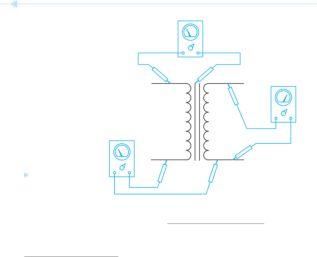
TESTING THE TRANSFORMER
There are several tests that can be made to deter-
mine the condition of the transformer. A simple
test for grounds, shorts, or opens can be made with
an ohmmeter, Figure 19–26. Ohmmeter A is con-
nected to one lead of the primary and one lead of
the secondary. This test checks for shorted windings
between the primary and secondary. The ohmmeter
should indicate in nity. If there is more than one
primary or secondary winding, all isolated windings
should be tested for shorts. Ohmmeter B illustrates
testing the windings for grounds. One lead of the
ohmmeter is connected to the case of the trans-
former and the other is connected to the winding.
All windings should be tested for grounds and the
ohmmeter should indicate in nity for each wind-
ing. Ohmmeter C illustrates testing the windings
for continuity. The wire resistance of the winding
should be indicated by the ohmmeter. Each winding
should be tested for continuity. If the transformer
appears to be in good condition after the ohmmeter
120120
240
7,200 VAC
Figure 19–23
Distribution transformer. (Source: Delmar/Cengage Learning)
120 VOLTS120 VOLTS
240 VOLTS
Figure 19–24
The voltage from either line to neutral is 120 volts.
The voltage across the entire secondary winding is
240 volts. (Source: Delmar/Cengage Learning)
120 VAC120 VAC
24A 30A
6A
Figure 19–25
The neutral carries the sum of the unbalanced current.
(Source: Delmar/Cengage Learning)
216 SECTION 4 Transformers
DETERMINING MAXIMUM
CURRENT
Notice that the nameplate does not list the current
rating of the windings. Because power input must
equal power output, the current rating for a wind-
ing can be determined by dividing the kVA rating
by the winding voltage. For example, assume a
transformer has a kVA rating of 0.5 kVA, a primary
voltage of 480 volts, and a secondary voltage of
120 volts. To determine the maximum current that
can be supplied by the secondary, divide the kVA
rating by the secondary voltage.
I
S
kVA
____
E
S
I
S
500
____
120
I
S
4.16 amps
test, it should then be tested for shorts and grounds
with a megohmmeter or “megger.” A megger will
reveal problems of insulation breakdown that an
ohmmeter will not.
TRANSFORMER RATINGS
Most transformers contain a nameplate that lists
information concerning the transformer. The infor-
mation listed is generally determined by the size,
type, and manufacturer. Almost all nameplates will
list the primary voltage, secondary voltage, and kVA
rating. Transformers are rated in kilovolt amps and
not kilowatts because the true power is determined
by the power factor of the load. Other information
that may or may not be listed is frequency, tempera-
ture rise in °C, % impedance (%Z), type of insulating
oil, gallon of insulating oil, serial number, type num-
ber, model number, and whether the transformer is
single phase or three phase.
B
C
A
Figure 19–26
Testing a transformer with
an ohmmeter. (Source: Delmar/
Cengage Learning)
UNIT 19 Isolation Transformers 217
direction of current ow causes the molecules of
iron in the core to realign themselves each time the
current changes direction. The molecules of iron
are continually rubbing against each other as they
realign magnetically. The friction of the molecules
rubbing together causes heat, which is a power
loss. Hysteresis loss is proportional to frequency.
The higher the frequency, the greater the loss. A
special steel called silicon steel is often used in
transformer cores to help reduce hysteresis loss. The
power loss due to hysteresis and eddy currents is
often called core loss.
Magnetic ux leakage does not produce heat, but
does constitute a power loss. Flux leakage is caused
by magnetic lines of ux radiating away from the
transformer and not cutting the secondary wind-
ings. Flux leakage can be reduced by better core
designs.
The primary current can be computed in the
same way.
I
P
kVA
____
E
P
I
P
500
____
480
I
P
1.04 amps
Transformers with multiple secondary windings
will generally have the current rating listed with the
voltage rating.
TRANSFORMER LOSSES
Although transformers are probably the most ef -
cient machines known, they are not perfect. A
transformer operating at 90% ef ciency has a power
loss of 10%. Some of these losses are I
2
R losses, eddy
current losses, hysteresis losses, and magnetic ux
leakage. Most of these losses result in heat produc-
tion. Recall that I
2
R is one of the formulas for nd-
ing power or watts. In the case of a transformer, it
describes the power loss associated with heat due
to the resistance of the wire in both primary and
secondary windings.
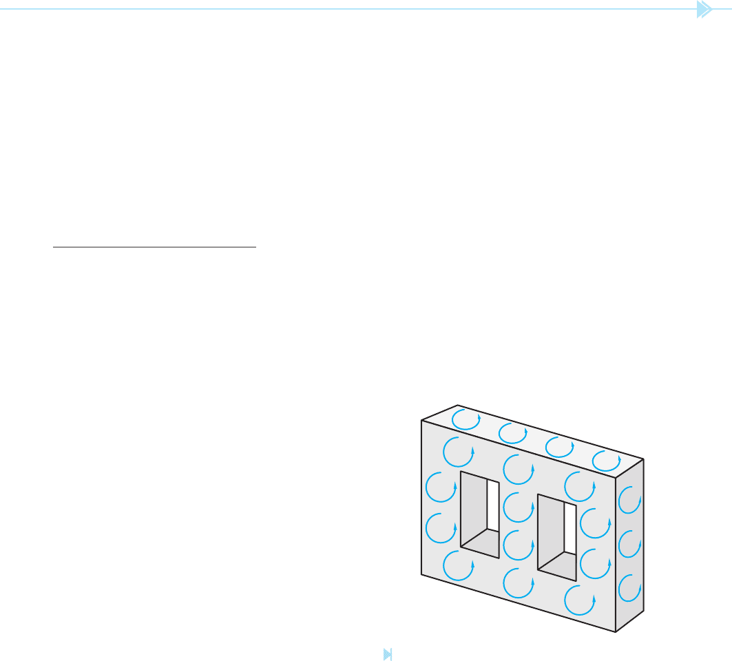
Eddy currents are currents that are induced into
the metal core material by the changing magnetic
eld as alternating current produces a changing
ux. Eddy currents are so named because they cir-
culate around inside the metal in a similar manner
as the swirling eddies in a river, Figure 19–27. These
swirling currents produce heat, which is a power
loss. Transformers are constructed with laminated
cores to help reduce eddy currents. The surface of
each lamination forms a layer of iron oxide, which
acts as an insulator to help prevent the formation of
eddy currents.
Hysteresis losses are losses due to molecular fric-
tion. As discussed previously, the reversal of the
Figure 19–27
Eddy currents circulate inside the core material. (Source:
Delmar/Cengage Learning)

218 SECTION 4 Transformers
SUMMARY
All values of voltage, current, and impedance in a transformer are proportional to the
turns ratio.
Transformers can change values of voltage, current, and impedance, but cannot change
the frequency.
The primary winding of a transformer is connected to the power line.
The secondary winding is connected to the load.
A transformer that has a lower secondary voltage than primary voltage is a step-down
transformer.
A transformer that has a higher secondary voltage than primary voltage is a step-up
transformer.
An isolation transformer has its primary and secondary windings electrically and
mechanically separated from each other.
When a coil induces a voltage into itself, it is known as self-induction.
When a coil induces a voltage into another coil, it is known as mutual induction.
Either winding of a transformer can be used as the primary or secondary as long as its
voltage or current ratings are not exceeded.
Isolation transformers help lter voltage and current spikes between the primary and sec-
ondary side.
KEY TERMS
core transformer mutual induction step-down transformer
E-I core self-induction step-up transformer
excitation current shell transformer tape wound or toroid
isolation transformer
silicon steel core
REVIEW QUESTIONS
1. What is a transformer?
2. What are common ef ciencies for transformers?
3. What is an isolation transformer?
4. All values of a transformer are proportional to its ___________ ___________
5. A transformer has a primary voltage of 480 volts and a secondary voltage of 20 volts.
What is the turns ratio of the transformer?
6. If the secondary of the transformer in question 5 supplies a current of 9.6 amperes to
a load, what is the primary current? (Disregard excitation current.)
7. Explain the difference between a step-up and a step-down transformer.
UNIT 19 Isolation Transformers 219
8. A transformer has a primary voltage of 240 volts and a secondary voltage of 48 volts.
What is the turns ratio of this transformer?
9. A transformer has an output of 750 volt amps. The primary voltage is 120 volts.
What is the primary current?
10. A transformer has a turns ratio of 1:6. The primary current is 18 amperes. What is
the secondary current?
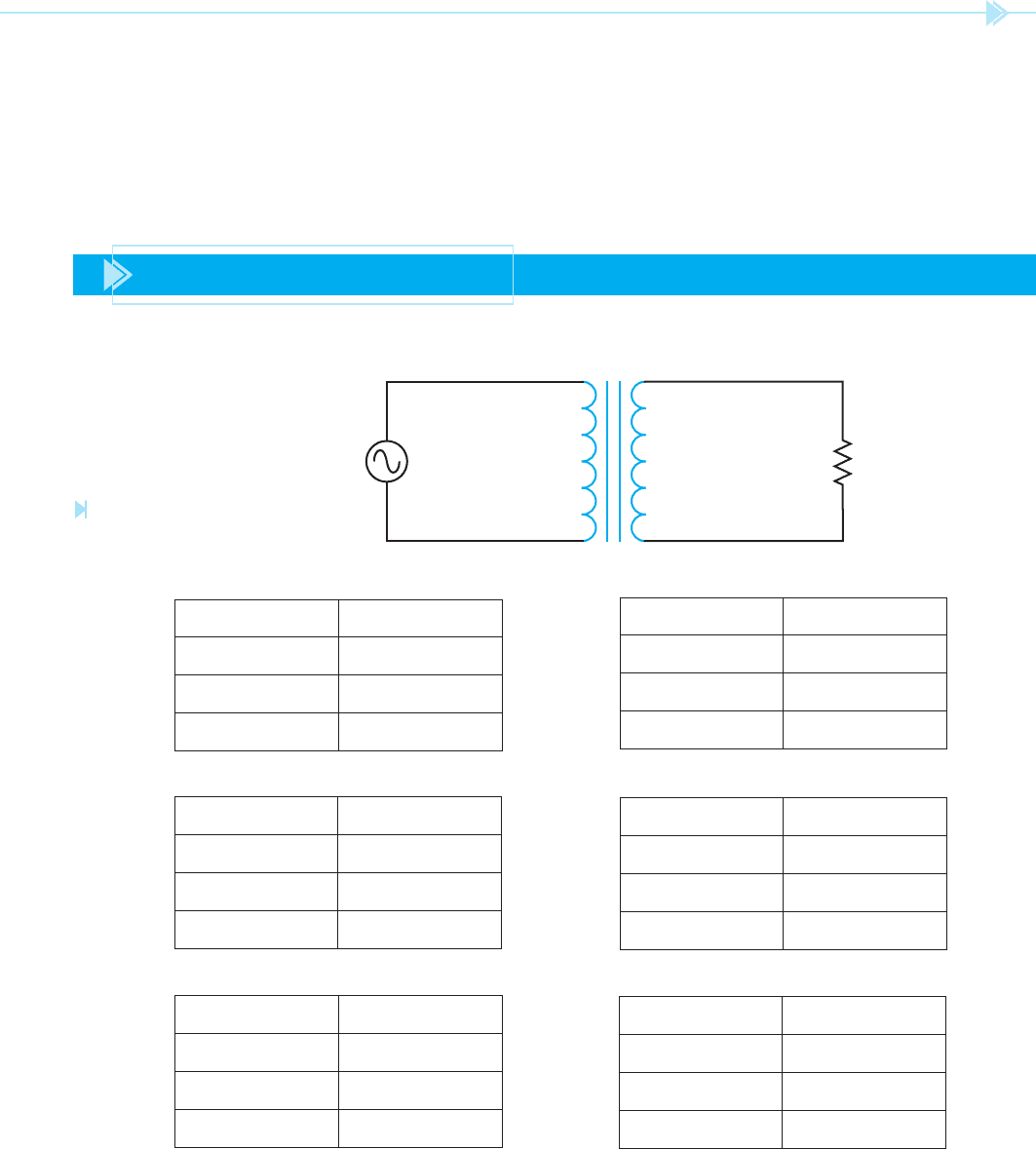
PRACTICE PROBLEMS
Refer to Figure 19–28 to answer the following questions. Find all missing values.
E
S
__________
I
S
__________
N
S
__________
E
P
__________
I
P
__________
N
P
__________
Z __________ Ω
RATIO: __________
Figure 19–28
Practice problems 1 through 6.
(Source: Delmar/Cengage Learning)
1.
3.
5.
E
P
120 E
S
24
I
P
I
S
N
P
300 N
S
Ratio: Z 3
Ω
E
P
_____
E
S
160
I
P
_____
I
S
_____
N
P
_____
N
S
80
Ratio: 1:2.5 Z 12
Ω
E
P
_____
E
S
_____
I
P
16.5 I
S
3.25
N
P
_____
N
S
450
Ratio:
_____
Z 56
Ω
2.
E
P
240 E
S
320
I
P
I
S
N
P
N
S
280
Ratio: Z 500
Ω
4.
E
P
48 E
S
240
I
P
_____
I
S
_____
N
P
220 N
S
_____
Ratio:
_____
Z 360
Ω
6.
E
P
480 E
S
_____
I
P
_____
I
S
_____
N
P
275 N
S
525
Ratio: Z 1.2 k
Ω