Stephen L. Herman, Bennie Sparkman. Electricity and Controls for HVAC-R (6th edition)
Подождите немного. Документ загружается.

220 SECTION 4 Transformers
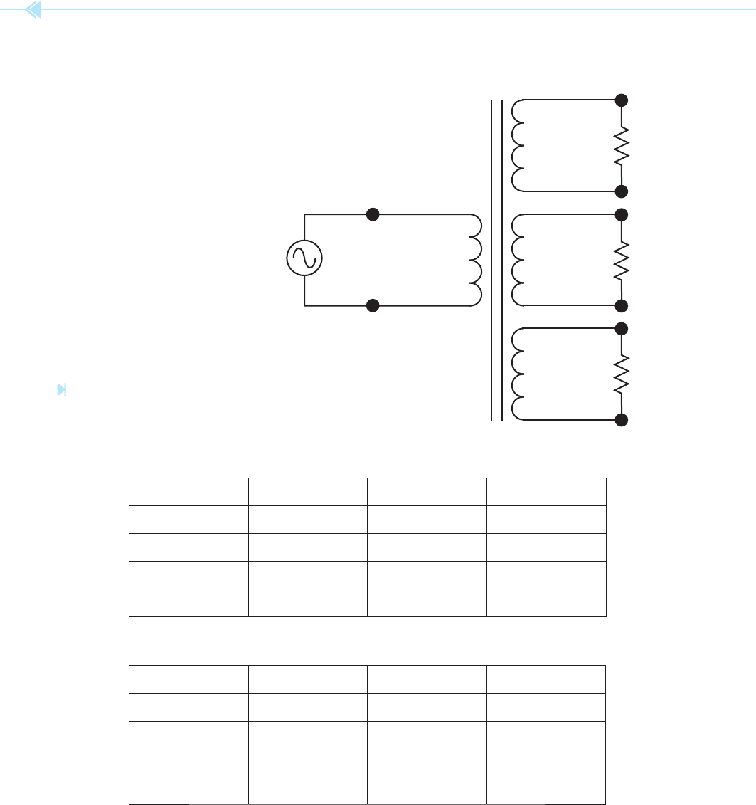
Refer to Figure 19–29 to answer the following questions. Find all missing values.
E
S
1 _________
I
S
1 _________
N
S
1 _________
R AT I O _________
E
S
2 _________
I
S
2 _________
N
S
2 _________
R AT I O _________
Z
1
_________ Ω
E
P
____________
I
P
____________
N
P
____________
Z
2
_________ Ω
E
S
3 _________
I
S
3 _________
N
S
3 _________
R AT I O _________
Z
3
_________ Ω
Figure 19–29
Practice problems 7 and 8. (Source:
Delmar/Cengage Learning)
7.
8.
E
P
208 E
S1
320 E
S2
120 E
S3
24
I
P
____ I
S1
____ I
S2
____ I
S3
____
N
P
800 N
S1
____ N
S2
____ N
S3
____
Ratio
1
____ Ratio
2
____ Ratio
3
____
R
1
12 k
Ω
R
2
6
Ω
R
3
8
Ω
E
P
277 E
S1
480 E
S2
208 E
S3
120
I
P
____ I
S1
____ I
S2
____ I
S3
____
N
P
350 N
S1
____ N
S2
____ N
S3
____
Ratio
1
____ Ratio
2
____ Ratio
3
____
R
1
200
Ω
R
2
60
Ω
R
3
24
Ω

221
The word auto means self. An autotransformer is
literally a self-transformer. It uses the same
winding as both the primary and secondary. Recall
that the de
nition of a primary winding is a
winding that is connected to the source of power,
and the de nition of a secondary winding is a
winding that is connected to a load. Autotransform-
ers have very high ef ciencies, most in the range of
95% to 98%.
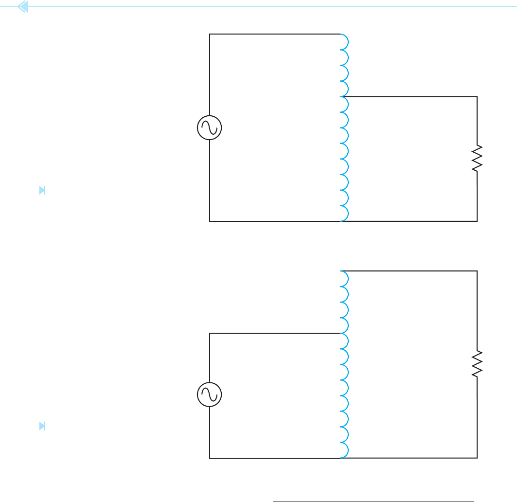
In Figure 20–1, the entire winding is connected
to the power source, and part of the winding is con-
nected to the load. In this illustration, all the turns
of wire form the primary and part of the turns form
the secondary. Because the secondary part of the
winding contains fewer turns than the primary sec-
tion, the secondary will produce less voltage. This
autotransformer is a
step-down transformer.
OBJECTIVES
After reading this unit the student should
be able to:
Discuss the operation of an
autotransformer
List differences between isolation
transformers and autotransformers
Compute values of voltage, current,
and turns ratios for autotransformers
Connect an autotransformer for
operation
Autotransformers
UNIT 20
222 SECTION 4 Transformers
SECONDARY
WINDING
PRIMARY
WINDING
Figure 20–1
Autotransformer used as a
step-down transformer.
(Source: Delmar/Cengage Learning)
Figure 20–2
Autotransformer used as a
step-up transformer.
(Source: Delmar/Cengage Learning)
SECONDARY
WINDING
PRIMARY
WINDING
In Figure 20–2, the primary section is connected
across part of a winding and the secondary is con-
nected across the entire winding. In this illustration
the secondary section contains more windings than
the primary. This autotransformer is a step-up
transformer. Notice that autotransformers, like iso-
lation transformers, can be used as step-up or step-
down transformers.
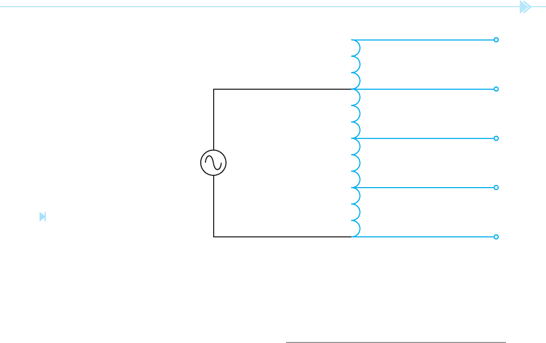
DETERMINING VOLTAGE VALUES
Autotransformers are not limited to a single second-
ary winding. Many autotransformers have mul-
tiple taps to provide different voltages as shown in
Figure 20–3. In this example, there are 40 turns of
wire between taps A and B, 80 turns of wire between
taps B and C, 100 turns of wire between taps C and D,
UNIT 20 Autotransformers 223
Figure 20–3
Autotransformer with multiple taps.
(Source: Delmar/Cengage Learning)
60 TURNS
E
PRIMARY
WINDING
D
100 TURNS
C
80 TURNS
B
40 TURNS
A
and 60 turns of wire between taps D and E. The pri-
mary section of the windings is connected between
taps B and E. It will be assumed that the primary
is connected to a source of 120 volts. The voltage
across each set of taps will be determined.
There is generally more than one method that can
be employed to determine values of a transformer.
Because the number of turns between each tap is
known, the volts-per-turn method will be used in
this example. The volts-per-turn for any transformer is
determined by the primary winding.
In this illustration,
the primary winding is connected across taps B and E.
The primary turns are, therefore, the sum of the turns
between taps B and E (80 100 60 240 turns).
Because 120 volts is connected across 240 turns,
this transformer will have a volts-per-turn ratio of
0.5 (240 turns/120 volts 0.5 volts-per-turn). To
determine the amount of voltage between each set
of taps, it becomes a simple matter of multiplying the
number of turns by the volts-per-turn.
A–B (40 turns 0.5 20 volts)
A–C (120 turns 0.5 60 volts)
A–D (220 turns 0.5 110 volts)
A–E (280 turns 0.5 140 volts)
B–C (80 turns 0.5 40 volts)
B–D (180 turns 0.5 90 volts)
B–E (240 turns 0.5 120 volts)
C–D (100 turns 0.5 50 volts)
C–E (160 turns 0.5 80 volts)
D–E (60 turns 0.5 30 volts)
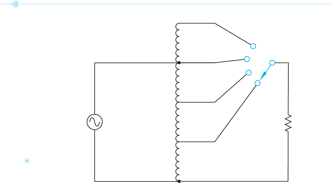
USING TRANSFORMER FORMULAS
The values of voltage and current for autotrans-
formers can also be determined by using standard
transformer formulas. The primary winding of the
transformer shown in Figure 20–4 is between points
B and N, and has a voltage of 120 volts applied to it.
If the turns of wire are counted between points B
and N, it can be seen that there are 120 turns of
wire. Now assume that the selector switch is set to
point D. The load is now connected between points
D and N. The secondary of this transformer contains
40 turns of wire. If the amount of voltage applied to
the load is to be computed, the following formula
can be used.
E
P
__
E
S
N
P
___
N
S
120
____
E
S
120
____
40
120 E
S
4800
E
S
40 volts
224 SECTION 4 Transformers
40 TURNS
D
40 TURNS
C
40 TURNS
B
40 TURNS
A
A
N
120 VAC
LOAD
B
C
D
Assume that the load connected to the secondary
has an impedance of 10 Ω. The amount of current
ow in the secondary circuit can be computed using
the formula:
I
E
__
Z
I
40
___
10
I 4 amps
The primary current can be computed by using the
same formula that was used to compute primary
current for an isolation type of transformer.
E
P
__
E
S
I
S
__
I
P
120 I
P
160
120
____
40
4
__
I
p
I
P
1.333 amps
The amount of power input and output for the auto-
transformer must also be the same.
Figure 20–4
Determining voltage
and current values.
(Source: Delmar/Cengage Learning)
Primary
120 1.333 160 volt-amps
Secondary
40 4 160 volt-amps
Now assume that the rotary switch is connected to
point A. The load is now connected to 160 turns
of wire. The voltage applied to the load can be
computed by:
E
P
__
E
S
N
P
___
N
S
120
____
E
S
120
____
60
120 E
S
19,200
E
S
160 volts
The amount of secondary current can be computed
using the formula:
I
E
__
Z
I
160
____
10
I 16 amps
UNIT 20 Autotransformers 225
The primary current can be computed using the
formula:
E
P
__
E
S
I
S
__
I
P
120
____
160
16
___
I
P
120 I
P
2,560
I
P
21.333 amps
The answers can be checked by determining if
the power in and power out are the same.
Primary
120 21.333 2,560 volt-amps
Secondary
160 16 2,560 volt-amps
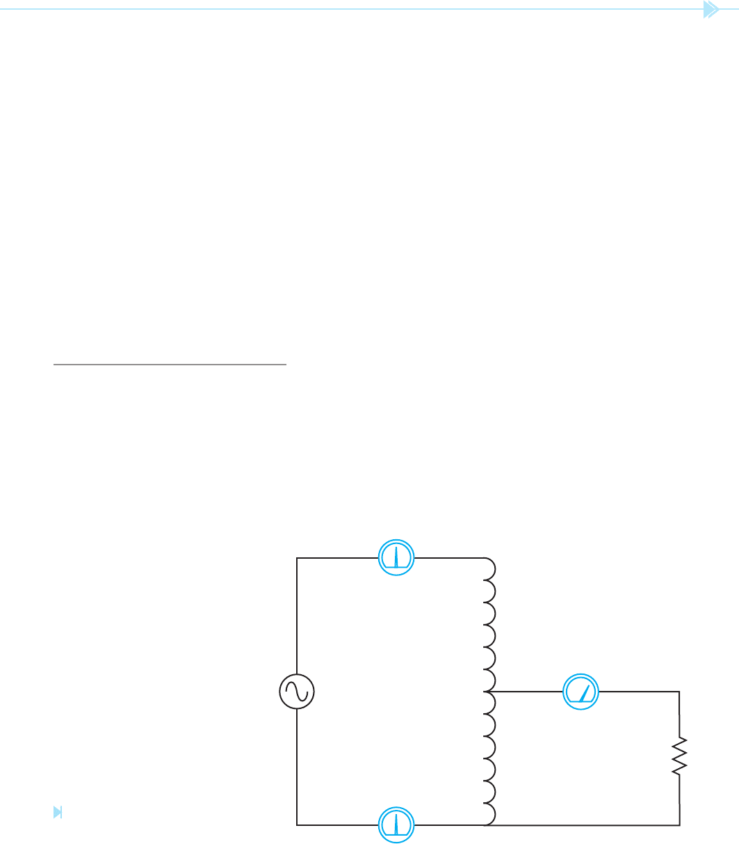
CURRENT RELATIONSHIPS
An autotransformer with a 2:1 turns ratio is shown
in Figure 20–5. It is assumed that a voltage of
480 volts is connected across the entire winding.
Because the transformer has a turns ratio of 2:1,
a voltage of 240 volts will be supplied to the load.
Ammeters connected in series with each winding
indicate the current ow in the circuit. It is assumed
that the load produces a current ow of 4 amperes
on the secondary. Note that a current ow of
2 amperes is supplied to the primary.
I
PRIMARY
I
SECONDARY
________
Ratio
I
p
4
__
2
I
p
2 amperes
If the rotary switch shown in Figure 20–4 were to
be removed and replaced with a sliding tap that
made contact directly to the transformer winding,
the turns ratio could be adjusted continuously.
This type of transformer is commonly referred to
as a Variac or Powerstat depending on the man-
ufacturer. The windings are wrapped around a
tape-wound toroid core inside a plastic case. The
tops of the windings have been milled at, similar
to a commutator. A carbon brush makes con-
tact with the windings. When the brush is moved
across the windings, the turns ratio changes, which
changes the output voltage. This type of autotrans-
former provides a very ef cient means of controlling
AC voltage.
Autotransformers are often used by power com-
panies to provide a small increase or decrease to the
line voltage. They help provide voltage regulation to
large power lines.
SECONDARY
WINDING
240 VAC
480 VAC
PRIMARY
WINDING
2 AMPS
2 AMPS
4 AMPS
Figure 20–5
Current divides between primary and
secondary. (Source: Delmar/Cengage Learning)

226 SECTION 4 Transformers
SUMMARY
The autotransformer has only one winding that is used as both the primary and secondary.
Autotransformers have ef ciencies that range from about 95% to 98%.
Values of voltage, current, and turns can be computed in the same manner as an isolation
transformer.
Autotransformers can be step-up or step-down transformers.
Autotransformers can be made to provide a variable output voltage by connecting a
sliding tap to the windings.
Autotransformers have the disadvantage of no line isolation between primary and secondary.
One of the simplest ways of computing values of voltage for an autotransformer when the
turns are known is to use the volts-per-turn method.
KEY TERMS
The autotransformer does have one disadvan-
tage. Because the load is connected to one side of
the power line, there is no
line isolation between
the incoming power and the load. This can cause
problems with certain types of equipment and must
be a consideration when designing a power system.
line isolation
multiple taps
primary winding
secondary winding
self-transformer
step-down
step-up
volts-per-turn
REVIEW QUESTIONS
1. An AC power source is connected across 325 turns of an autotransformer and the
load is connected across 260 turns. What is the turns ratio of this transformer?
2. Is the transformer in question 1 a step-up or a step-down transformer?
3. An autotransformer has a turns ratio of 3.2:1. A voltage of 208 volts is connected
across the primary. What is the voltage of the secondary?
4. A load impedance of 52 Ω is connected to the secondary winding of the transformer
in question 3. How much current will ow in the secondary?
5. How much current will ow in the primary of the transformer in question 4?
6. The autotransformer shown in Figure 20–3 has the following number of turns
between windings: A–B (120 turns), B–C (180 turns), C–D (250 turns), and D–E
(300 turns). A voltage of 240 volts is connected across B and E. Find the voltages
between each of the following pairs of points:
A–B ________ A–C ________ A–D ________ A–E ________
B–C ________ B–D ________ B–E ________ C–D ________
C–E ________ D–E ________

227
Current transformers differ from voltage transform-
ers in that the primary winding is generally part of
the power line. The primary winding of a current
transformer must be connected in series with the
load, Figure 21–1. Current transformers are used
to change the full scale range of AC ammeters.
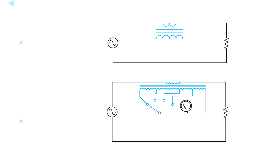
Most
in-line ammeters (ammeters that must be
connected directly into the line) that have multiple
range values used a current transformer to provide
the different ranges, Figure 21–2. The full scale value
of the ammeter is changed by changing the turns
ratio. Assume that the ammeter illustrated in Fig-
ure 21–2 is to provide range values of
5 amperes,
2.5 amperes, 1 ampere, and 0.5 ampere. Also
assume that the meter movement requires a current
ow of 100 mA (0.100) to de ect the meter full scale
and that the primary of the current transformer
contains 5 turns of wire. Transformer formulas can
OBJECTIVES
After studying this unit the student should
be able to:
Discuss the operation of a current
transformer
Describe how current transformers
differ from voltage transformers
Discuss safety precautions that should
be observed when using current
transformers
Connect a current transformer in
a circuit
Current
Transformers
UNIT 21
228 SECTION 4 Transformers
LOAD
CURRENT TRANSFORMER
LOADALTERNATOR
AC AMMETER
CURRENT TRANSFORMER
be used to determine the number of secondary turns
needed to produce the desired ranges. Turns needed
for a full scale range of 5 amperes.
N
P
___
N
S
⫽
I
S
__
I
P
5
___
N
S
⫽
0.1
____
5
0.1N
S
⫽ 25
N
S
⫽ 250 turns
Turns needed for a full scale range of 2.5 amperes.
5
___
N
S
⫽
0.1
____
2.5
0.1N
S
⫽ 12.5
N
S
⫽ 125 turns
Turns needed for a full scale range of 1 ampere.
5
___
N
S
⫽
0.1
____
1
0.1N
S
⫽ 5
N
S
⫽ 50 turns
Turns needed for a full scale range of
0.5 ampere.
5
___
N
S
⫽
0.1
____
0.5
0.1N
S
⫽ 2.5
N
S
⫽ 25 turns
When a large amount of AC current must be
measured, a different type of current transformer
is connected in the power line. These transform-
ers have ratios that start at 100:5 and can have
ratios of several thousand to ve. These current
transformers, generally referred to in industry
as CTs, have a standard secondary current rating
of 5 amps AC. They are designed to be operated
with a 5 amp AC ammeter connected directly to
their secondary winding, which produces a short
circuit. CTs are designed to operate with the sec-
ondary winding shorted. The secondary winding
of a CT should never be opened when there is
power applied to the primary. This will cause the
transformer to produce a step-up in voltage which
could be high enough to kill anyone who comes in
contact with it.
Figure 21–1
The primary winding of a current
transformer is connected in series
with a load. (Source: Delmar/Cengage
Learning)
Figure 21–2
A current transformer is used
to change the range of an
AC ammeter. (Source: Delmar/Cengage
Learning)
UNIT 21 Current Transformers 229
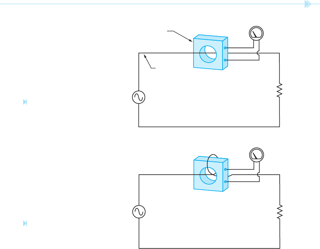
Figure 21–3
Current transformer used to
change the scale factor of an
AC ammeter. (Source: Delmar/Cengage
Learning)
Figure 21–4
The primary conductor loops through
the CT to produce a second turn,
changing the turns ratio. (Source: Delmar/
Cengage Learning)
LOAD
ALTERNATOR
CURRENT
TRANSFORMER
POWER LINE
ACTS AS A
PRIMARY WINDING
OF ONE TURN
5 AMPS AC
LOAD
ALTERNATOR
5 AMPS AC
A current transformer of this type is basically
a toroid transformer. A toroid transformer is con-
structed with a hollow core similar to a donut in that
it has a hole in the middle. When current transform-
ers are used, the main power line is inserted through
the opening in the transformer, Figure 21–3. The
power line acts as the primary of the transformer
and is considered to be one turn.
The turns ratio of the transformer can be changed
by looping the power wire through the opening in
the transformer to produce a primary winding of
more than one turn. For example, assume a current
transformer has a ratio of 600:5. If the primary
power wire is inserted through the opening, it will
require a current of 600 amps to de ect the meter
full scale. If the primary power conductor is looped
around and inserted through the window a sec-
ond time, the primary now contains two turns of
wire instead of one, Figure 21–4. It now requires
300 amps of current ow in the primary to de ect
the meter full scale. If the primary conductor is
looped through the opening a third time, it would
require only 200 amps of current ow to de ect the
meter full scale.