Stephen L. Herman, Bennie Sparkman. Electricity and Controls for HVAC-R (6th edition)
Подождите немного. Документ загружается.


Transformers are one of the most common devices
found in the HVAC eld. They range in size from
occupying a space of less than 1 cubic inch to
requiring rail cars to move them after they have
been broken into sections. Their ratings can range
from mVA (millivolt amps) to GVA (gigavolt amps).
A transformer is a magnetically operated machine
that can change values of voltage, current, and
impedance without a change of frequency.
Transformers are the most ef cient machines
known. Their ef ciencies commonly range from
90% to 99% at full load. Transformers can be
divided into several classi cations such as:
A. Isolation.
B. Auto.
C. Current.
200
OBJECTIVES
After studying this unit the student should
be able to:
Discuss the different types of
transformers
Calculate values of voltage, current,
and turns for single-phase transformers
using formulas
Calculate values of voltage, current,
and turns for a single-phase
transformer using the turns ratio
Connect a transformer and test the
voltage output of different windings
UNIT 19
Isolation
Transformers
UNIT 19 Isolation Transformers 201
N
S
Number of turns in the secondary
E
P
Voltage of the primary
E
S
Voltage of the secondary
I
P
Current in the primary
I
S
Current in the secondary
E
P
__
E
S
N
P
___
N
S
E
P
__
E
S
I
S
__
I
p
N
P
___
N
S
I
S
__
I
p
or
E
P
N
S
E
S
N
P
E
P
I
P
E
S
I
S
N
P
I
P
N
S
I
S
The primary winding of a transformer is the
power input winding. It is the winding that is con-
nected to the incoming power supply. The second-
ary winding is the load winding or output winding.
It is the side of the transformer that is connected
to the driven load, Figure 19–2. Any winding of a
transformer can be used as a primary or secondary
winding provided its voltage or current rating is not
exceeded. Transformers can also be operated at a
lower voltage than their rating indicates, but they
cannot be connected to a higher voltage. Assume
the transformer shown in Figure 19–2, for example,
has a primary voltage rating of 480 volts and the
secondary has a voltage rating of 240 volts. Now
assume that the primary winding is connected to
a 120-volt source. No damage would occur to the
transformer, but the secondary winding would pro-
duce only 60 volts.
ISOLATION TRANSFORMERS
The transformers shown in Figures 19–1 and 19–2
are isolation transformers. This means that
the secondary winding is physically and electri-
cally isolated from the primary winding. There is
A basic law concerning transformers is that all
values of a transformer are proportional to its turns
ratio
. This does not mean that the exact number
of turns of wire on each winding must be known
to determine different values of voltage and cur-
rent for a transformer. What must be known is the
ratio of turns. For example, assume a transformer
has two windings. One winding, the primary, has
1,000 turns of wire and the other, the secondary,
has 250 turns of wire, Figure 19–1. The turns ratio
of this transformer is 4 to 1 or 4:1 (1,000/250 4).
This indicates there are four turns of wire on the pri-
mary for every one turn of wire on the secondary.
TRANSFORMER FORMULAS
There are different formulas that can be used to nd
the values of voltage and current for a transformer.
The following is a list of standard formulas:
Where:
N
P
Number of turns in the primary
SECONDARY
250 TURNS
PRIMARY
1,000 TURNS
Figure 19–1
All values of a transformer are proportional to its turns
ratio. (Source: Delmar/Cengage Learning)
SECONDARY LOADPRIMARY
Figure 19–2
Isolation transformer.
(Source: Delmar/Cengage Learning)
202 SECTION 4 Transformers
no electrical connection between the primary and
secondary winding. This transformer is magneti-
cally coupled, not electrically coupled. This “line
isolation” is often a very desirable characteristic.
Because there is no electrical connection between
the load and power supply, the transformer becomes
a lter between the two. The isolation transformer
will greatly reduce any voltage spikes that originate
on the supply side before they are transferred to the
load side. Some isolation transformers are built with
a turns ratio of 1:1. A transformer of this type will
have the same input and output voltage and is used
for the purpose of isolation only.
The reason that the transformer can greatly
reduce any voltage spikes before they reach the
secondary is because of the rise time of current
through an inductor. The current in an inductor
rises at an exponential rate, Figure 19–3. As the
current increases in value, the expanding magnetic
eld cuts through the conductors of the coil and
induces a voltage that is opposed to the applied volt-
age. The amount of induced voltage is proportional
to the rate of change of current. This simply means
EXPONENTIAL CURVE
CURRENT
TIME
Figure 19–3
The current through
an inductor rises at
an exponential rate.
(Source: Delmar/Cengage
Learning)
that the faster the current attempts to increase, the
greater the opposition to that increase will be. Spike
voltages and currents are generally of very short
duration, which means that they increase in value
very rapidly, Figure 19–4. This rapid change of value
causes the opposition to the change to increase just
as rapidly. By the time the spike has been transferred
to the secondary winding of the transformer, it has
been eliminated or greatly reduced, Figure 19–5.
Another purpose of isolation transformers is to
remove some piece of electrical equipment from
ground. It is sometimes desirable that a piece of
electrical equipment not be connected directly to
ground. This is often done as a safety precaution
to eliminate the hazard of an accidental contact
between a person at ground potential and the
ungrounded conductor. If the case of the equipment
should come in contact with the ungrounded con-
ductor, the isolation transformer would prevent a
circuit being completed to ground through someone
touching the case of the equipment. Many alter-
nating current circuits have one side connected to
ground. A familiar example of this is the common
UNIT 19 Isolation Transformers 203
TRANSFORMER CONSTRUCTION
The basic construction of an isolation transformer is
shown in Figure 19–7. A metal core is used to provide
good magnetic coupling between the two windings.
The core is generally made of laminations stacked
together. Laminating the core helps reduce power
losses due to eddy current induction. Figure 19–7
shows the basic design of electrically separated
winding.
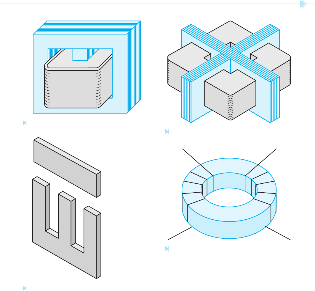
TRANSFORMER CORE TYPES
There are several different types of cores used in the
construction of transformers. Most cores are made
from thin steel punchings laminated together to
form a solid metal core. Laminated cores are pre-
ferred because a thin layer of oxide forms on the sur-
face of each lamination, which acts as an insulator
to reduce the formation of eddy currents inside the
core material. The amount of core material needed
for a particular transformer is determined by the
power rating of the transformer. The amount of core
material must be suf cient to prevent saturation
at full load. The type and shape of the core gener-
ally determines the amount of magnetic coupling
between the windings and to some extent the ef -
ciency of the transformer.
DURATION OF
VOLTAGE SPIKE
SINE WAVE
VOLTAGE
SPIKE VOLTAGE
Figure 19–4
Voltage spikes are generally of short duration.
(Source: Delmar/Cengage Learning)
SECONDARY LOADPRIMARY
Figure 19–5
The isolation transformer greatly reduces
the voltage spike. (Source: Delmar/Cengage Learning)
120-volt circuit with a grounded neutral conduc-
tor, Figure 19–6. An isolation transformer can be
used to remove a piece of equipment from circuit
ground.
204 SECTION 4 Transformers
shell type has a metal core piece through the middle
of the window, Figure 19–9. The primary and sec-
ondary windings are wound around the center core
piece with the low voltage winding being closest to
the metal core. This arrangement permits the trans-
former to be surrounded by the core, which provides
The transformer illustrated in Figure 19–8 is known
as a core transformer. The windings are placed
around each end of the core material. The metal core pro-
vides a good magnetic path between the two windings.
The shell transformer is constructed in a
similar manner as the core type, except that the
120 VAC
EQUIPMENT
EQUIPMENT HAS
NO CONNECTION
T
O GROUND
GROUNDED LINE
UNGROUNDED LINE
Figure 19–6
Isolation transformer
used to remove a
piece of electrical
equipment from
ground. (Source: Delmar/
Cengage Learning)
WINDING
IRON CORE
WINDING
Figure 19–7
Basic construction of an isolation
transformer. (Source: Delmar/Cengage
Learning)
COIL
COIL
CORE
Figure 19–8
Core-type transformer. (Source: Delmar/Cengage
Learning)
UNIT 19 Isolation Transformers 205
through its center around which the primary and
secondary windings are wound. The H core, how-
ever, surrounds the windings on four sides instead
of two. This extra metal helps reduce stray leakage
ux and improve the ef ciency of the transformer.
The H-type core is often found on high voltage dis-
tribution transformers.
The tape wound or toroid core, Figure 19–12,
is constructed by tightly winding one long continu-
ous silicon steel tape into a spiral. The tape may or
may not be housed in a plastic container depend-
ing on the application. This type core does not
require steel punchings that are then laminated
together. Because the core is one continuous length
excellent magnetic coupling. When the trans-
former is in operation, all the magnetic ux
must
pass through the center core piece. It then divides
through the two outer core pieces. Shell type cores
are sometimes referred to as E-I cores because the
steel punchings used to construct the core are in the
shape of an E and an I, Figure 19–10.
The H-type core shown in Figure 19–11 is simi-
lar to the shell type core in that it has an iron core
Figure 19–9
Shell-type transformer. (Source: Delmar/Cengage Learning)
I LAMINATION
E LAMINATION
Figure 19–10
Shell-type cores are made of E and I laminations.
(Source: Delmar/Cengage Learning)
Figure 19–11
Transformer with H-type core. (Source: Delmar/Cengage Learning)
Figure 19–12
Toroid transformer. (Source: Delmar/Cengage Learning)
206 SECTION 4 Transformers
transformers with a large kVA rating will appear to
be almost a short circuit when measured with an
ohmmeter. When connected to power, however, the
actual no load current is generally relatively small.
EXCITATION CURRENT
There will always be some amount of current ow in
the primary of a transformer even if there is no load
connected to the secondary. This is called the exci-
tation current of the transformer. The excitation
current is the amount of current required to magne-
tize the core of the transformer. The excitation cur-
rent remains constant from no load to full load. As
a general rule, the excitation current is such a small
part of the full load current, it is often omitted when
making calculations.
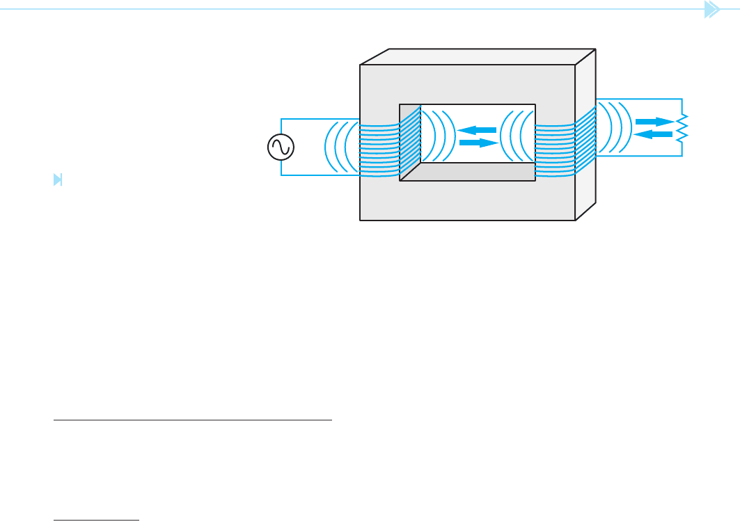
MUTUAL INDUCTION
Because the secondary windings are wound on the
same core as the primary, the magnetic eld pro-
duced by the primary winding cuts the windings
of the secondary also, Figure 19–14. This continu-
ally changing magnetic eld induces a voltage into
the secondary winding. The ability of one coil to
induce a voltage into another coil is called mutual
induction. The amount of voltage induced in
the secondary is determined by the number of
turns of wire in the secondary as compared with
of metal, ux leakage is kept to a minimum. The tape
wound core is one of the most ef cient core designs
available.
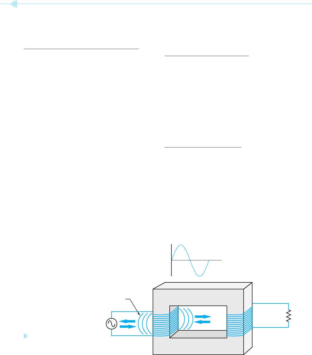
BASIC OPERATING PRINCIPLES
In Figure 19–13, one winding of the transformer
has been connected to an alternating current sup-
ply, and the other winding has been connected to
a load. As current increases from zero to its peak
positive point, a magnetic eld expands outward
around the coil. When the current decreases from
its peak positive point toward zero, the magnetic
eld collapses. When the current increases toward
its negative peak, the magnetic eld again expands,
but with an opposite polarity of that previously. The
eld again collapses when the current decreases
from its negative peak toward zero. This continually
expanding and collapsing magnetic eld cuts the
windings of the primary and induces a voltage into
it. This induced voltage opposes the applied voltage
and limits the current ow of the primary. When
a coil induces a voltage into itself, it is known as
self-induction. It is this induced voltage, induc-
tive reactance, that limits the
ow of current in the
primary winding. If the resistance of the primary
winding is measured with an ohmmeter, it will indi-
cate only the resistance of the wire used to construct
the winding and will not give an indication of the
actual current limiting effect of the winding. Most
MAGNETIC
FIELD
Figure 19–13
Magnetic fi eld produced
by alternating current.
(Source: Delmar/Cengage Learning)
UNIT 19 Isolation Transformers 207
next problem is to calculate the current ow in the
secondary and primary windings. The current ow
of the secondary can be computed using Ohm’s law
since the voltage and impedance are known.
I
E
__
Z
I
30
___
5
I 6 amps
Now that the amount of current ow in the second-
ary is known, the primary current can be computed
using the formula:
E
P
__
E
S
I
S
__
I
P
120
____
30
6
__
I
P
120 I
P
180
I
P
1.5 amps
Notice that the primary voltage is higher than the
secondary voltage, but the primary current is much
less than the secondary current. A good rule for
transformers is that power in must equal power out.
If the primary voltage and current are multiplied
together, it should equal the product of the voltage
and current of the secondary:
Primary
120 1.5 180 volt amps
Secondary
30 6 180 volt amps
the primary. For example, assume the primary has
240 turns of wire and is connected to 120 volts
AC. This gives the transformer a volts-per-turn
ratio of 0.5 (120 volts per 240 turns 0.5 volt per
turn). Now assume the secondary winding contains
100 turns of wire. Because the transformer has a
volts-per-turn ratio of 0.5, the secondary voltage
will be 50 volts (100 0.5 50).
TRANSFORMER CALCULATIONS
In the following examples, values of voltage, cur-
rent, and turns for different transformers will be
computed.
EXAMPLE
Assume the isolation transformer shown in
Figure 19–2 has 240 turns of wire on the primary
and 60 turns of wire on the secondary. This is a ratio
of 4:1 (240/60 4). Now assume that 120 volts is
connected to the primary winding. What is the volt-
age of the secondary winding?
E
P
__
E
S
N
P
___
N
S
120
____
E
S
240
____
60
E
S
30 volts
The transformer in this example is known as a
step-down transformer because it has a lower
secondary voltage than primary voltage.
Now assume that the load connected to the
secondary winding has an impedance of 5 . The
Figure 19–14
The magnetic fi eld of the primary
induces a voltage into the
secondary. (Source: Delmar/Cengage Learning)
208 SECTION 4 Transformers
120 I
P
150
I
P
1.25 amps
Notice that the amount of power input equals the
amount of power output.
Primary
120 1.25 150 volt amps
Secondary
600 0.25 150 volt amps
CALCULATING TRANSFORMER
VALUES USING THE TURNS RATIO
As illustrated in the previous examples, transformer
values of voltage, current, and turns can be com-
puted using formulas. It is also possible to compute
these same values using the turns ratio. There are
several ways in which turns ratios can be expressed.
One method is to use a whole number value such as
13:5 or 6:21. The rst ratio indicates that one wind-
ing has 13 turns of wire for every 5 turns of wire in
the other winding. The second ratio indicates that
there are 6 turns of wire in one winding for every
21 turns in the other.
A second method is to use the number 1 as a
base. When using this method, the number 1 is
always assigned to the winding with the lowest volt-
age rating. The ratio is found by dividing the higher
voltage by the lower voltage. The number on the
left side of the ratio represents the primary winding,
and the number on the right of the ratio represents
the secondary winding. For example, assume a
transformer has a primary rated at 240 volts and
a secondary rated at 96 volts, Figure 19–15. The
EXAMPLE
In the next example, assume that the primary wind-
ing contains 240 turns of wire and the secondary
contains 1,200 turns of wire. This is a turns ratio of
1:5 (1,200/240 5). Now assume that 120 volts
is connected to the primary winding. Compute the
voltage output of the secondary winding.
E
P
__
E
S
N
P
___
N
S
120
____
E
S
240
_____
1200
240 E
S
144,000
E
S
600 volts
Notice that the secondary voltage of this trans-
former is higher than the primary voltage. This type of
transformer is known as a step-up transformer.
Now assume that the load connected to the
secondary has an impedance of 2,400 . Find the
amount of current
ow in the primary and second-
ary windings. The current ow in the secondary
winding can be computed using Ohm’s law.
I
E
__
Z
I
600
_____
2400
I 0.25 amp
Now that the amount of current ow in the second-
ary is known, the primary current can be computed
using the formula:
E
P
__
E
S
I
S
__
I
P
120
____
600
0.25
_____
I
P
LOAD
24 OHMS
240 VAC 96 VAC
RATIO: 2.5:1
Figure 19–15
Computing transformer values using
the turns ratio. (Source: Delmar/Cengage
Learning)

UNIT 19 Isolation Transformers 209
Now assume that the secondary winding contains
150 turns of wire. The primary turns can also
be found by using the turns ratio. Because the
primary voltage is higher than the secondary volt-
age, the primary must have more turns of wire.
Because the primary must contain more turns of
wire, the secondary turns will be multiplied by the
turns ratio.
N
P
N
S
Turns Ratio
N
P
150 2.5
N
P
375 turns
In the next example, assume a transformer has
a primary voltage of 120 volts and a secondary
voltage of 500 volts. The secondary has a load
impedance of 1,200 . The secondary contains
800 turns of wire, Figure 19–16. The turns ratio
can be found by dividing the higher voltage by the
lower voltage.
Ratio
500
____
120
Ratio 1:4.17
The secondary current can be found using
Ohm’s law.
I
S
500
_____
1200
I
S
0.417 amp
In this example, the primary voltage is lower
than the secondary voltage. Therefore, the primary
current must be higher. To nd the primary current,
multiply the secondary current by the turns ratio.
I
P
I
S
Turns Ratio
I
P
0.417 4.17
I
P
1.74 amps
turns ratio can be computed by dividing the higher
voltage by the lower voltage.
Ratio
240
____
96
Ratio 2.5:1
Notice in this example that the primary winding has
the higher voltage rating and the secondary has the
lower. Therefore, the 2.5 is placed on the left and the
base unit, 1, is placed on the right. This ratio indicates
that there are 2.5 turns of wire in the primary winding
for every 1 turn of wire in the secondary.
Now assume that there is a resistance of 24
connected to the secondary winding. The amount of
secondary current can be found using Ohm’s law.
I
S
96
___
24
I
S
4 amps
The primary current can be found using the turns
ratio. Recall that the volt amps of the primary must
equal the volt amps of the secondary. Because the pri-
mary voltage is greater, the primary current will have
to be less than the secondary current. Therefore, the
secondary current will be divided by the turns ratio.
I
P
I
S
__________
Turns Ratio
I
P
4
___
25
I
P
1.6 amps
To check the answer, nd the volt amps of the
primary and secondary.
Primary
240 1.6 384
Secondary
96 4 384
E
S
120
I
S
N
S
800
E
P
120
I
P
N
P
Z = 1200Ω
RATIO:
Figure 19–16
Calculating transformer values.
(Source: Delmar/Cengage Learning)