Stephen L. Herman, Bennie Sparkman. Electricity and Controls for HVAC-R (6th edition)
Подождите немного. Документ загружается.

170 SECTION 3 Motors
TR
CONTROL TRANSFORMER
S
TR
S
2C
TR
THERMOSTAT
1C
2C
OL
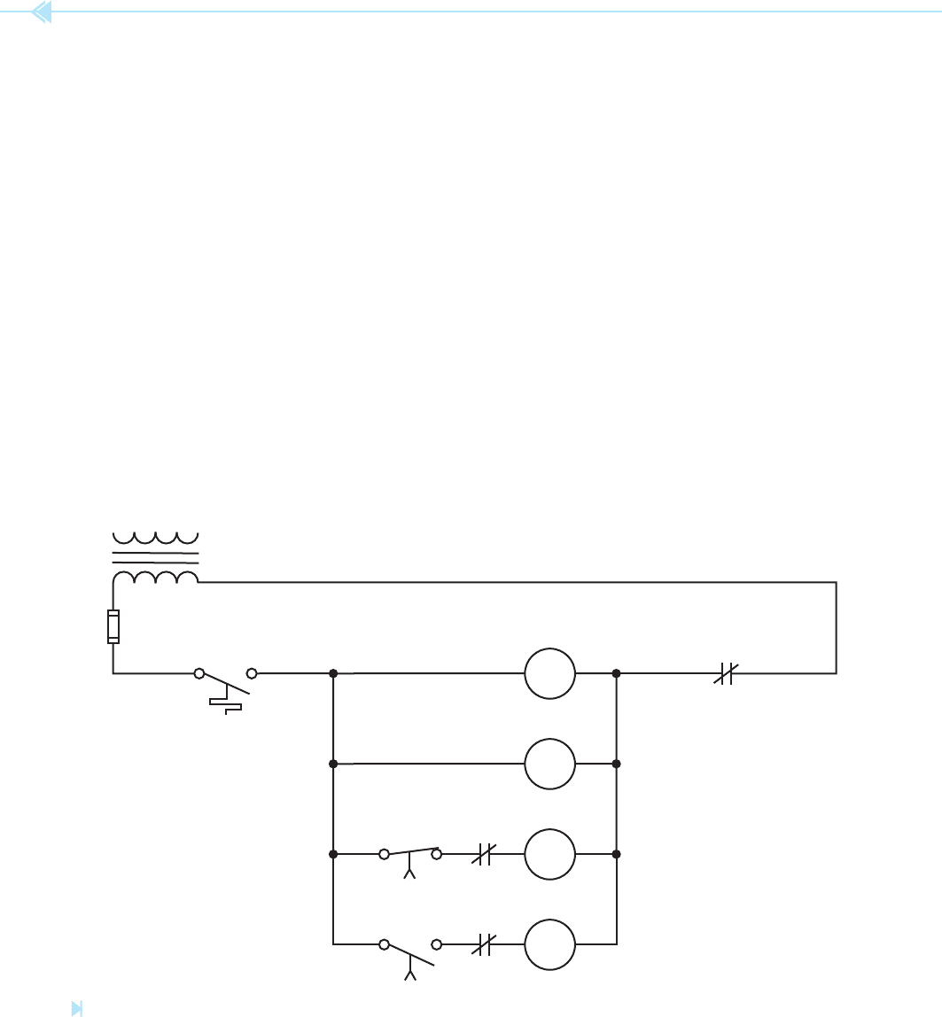
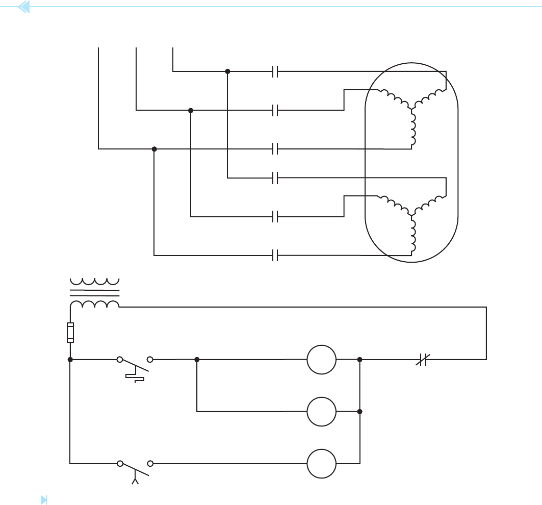
A basic control schematic for a wye-delta starter
is shown in Figure 15–22. To understand the opera-
tion of this circuit assume that timer TR has been set
for a delay of 3 seconds.
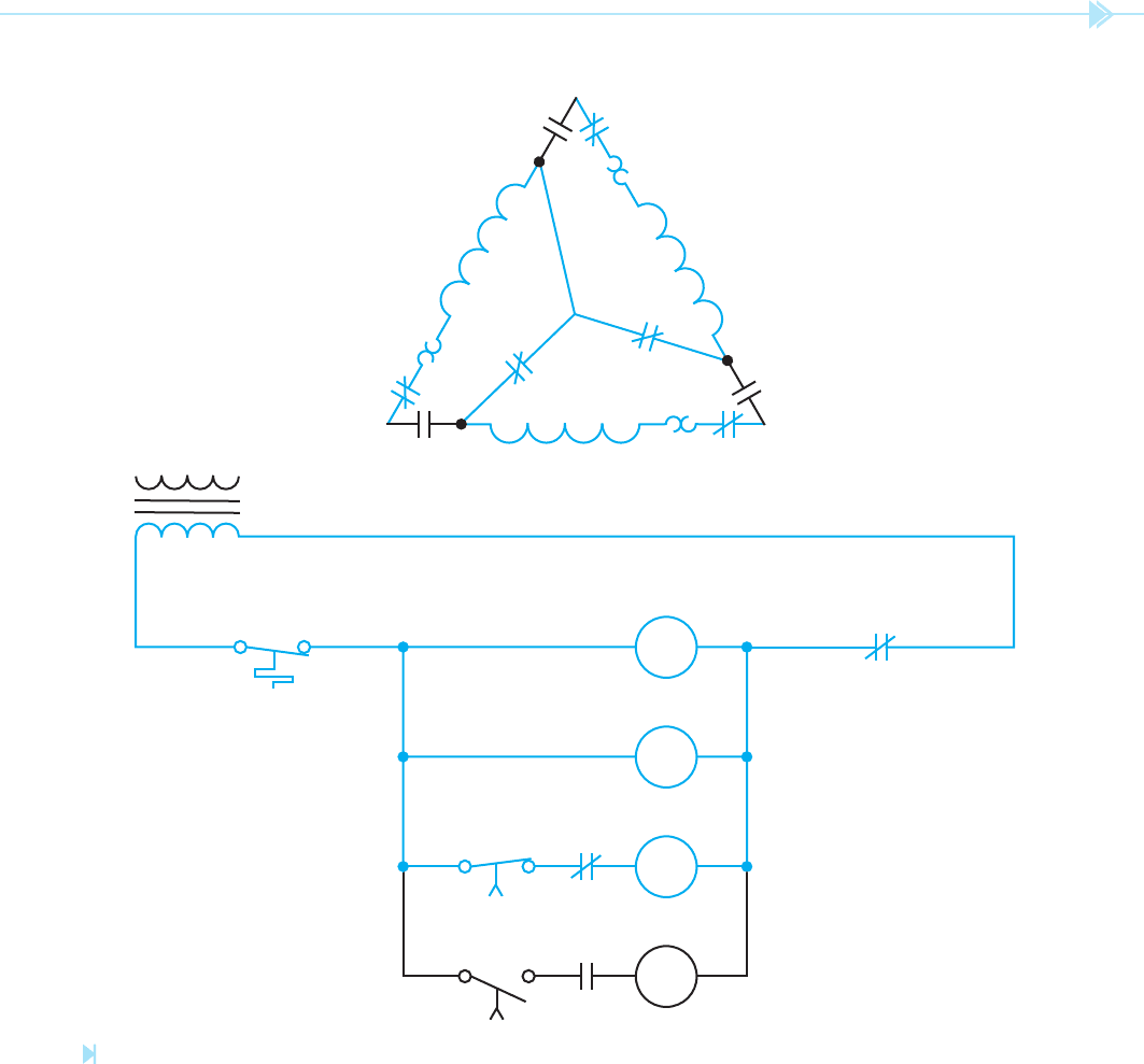
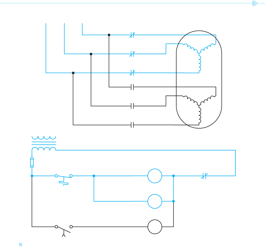
• When the thermostat contact closes, a current path
exists through coils 1C, TR, and S, Figure 15–23.
• The 1C load contacts close to supply power to the
motor T leads.
• The S contacts change position also. The two S
load contacts close and connect the stator wind-
ing in a wye con guration by shorting T4, T5,
and T6 together. The normally open S contact
connected in series with coil 2C opens to provide
interlocking protection.
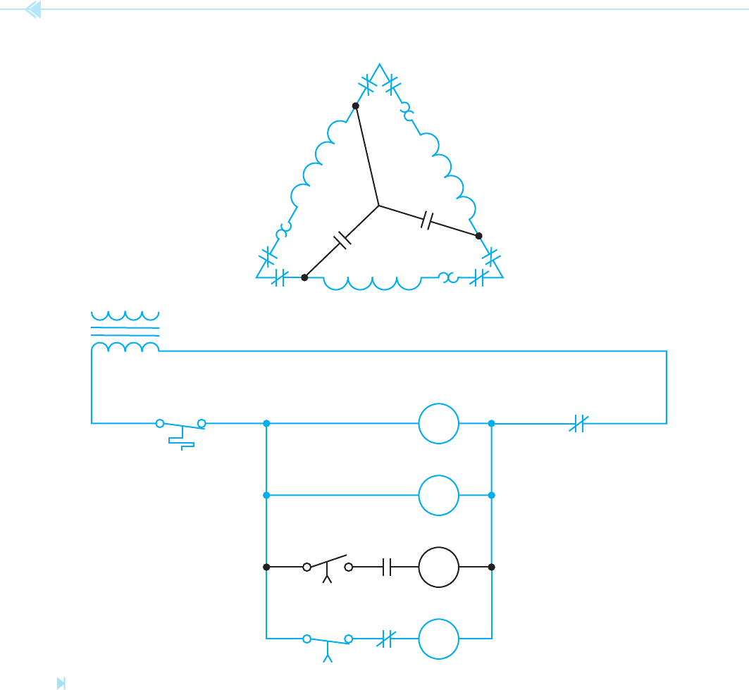
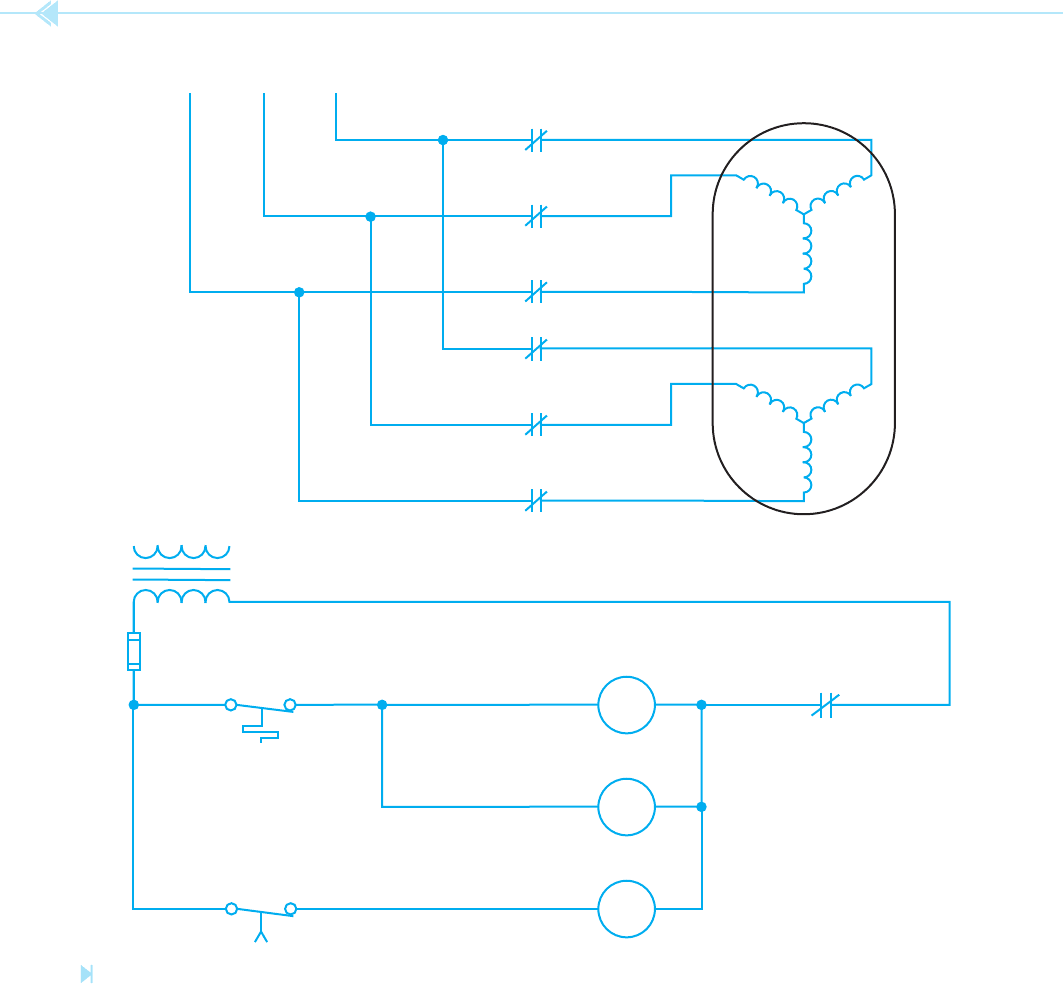
• After a delay of 3 seconds, both TR contacts
change position, Figure 15–24.
• The normally closed TR contact connected in
series with S coil opens and deenergizes S contactor
causing all S contacts to return to their normal
position. The normally closed S contact connected
in series with coil 2C recloses to provide a current
path to coil 2C.
• When the normally open TR contact connected
in series with coil 2C closes, coil 2C energizes
causing all 2C contacts to change position. The
2C load contacts close and reconnect the motor
stator windings in a delta con guration. The nor-
mally closed 2C contact connected in series with
S coil opens to provide interlocking protection.
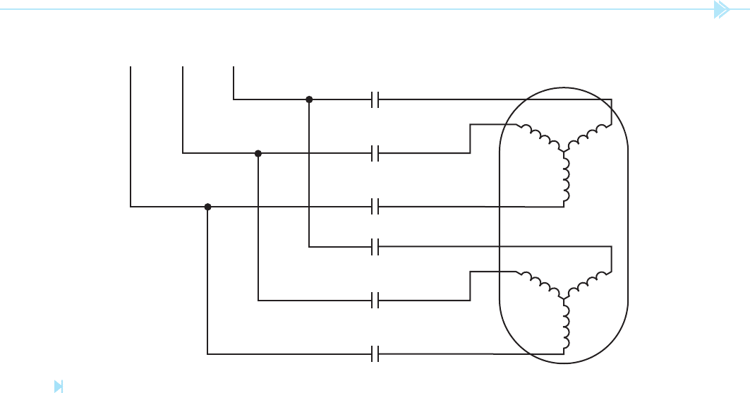
Part Winding Starters
Another method for reducing the starting current
of large three-phase squirrel-cage motors is part
winding starting. Motors intended for use with
part winding starting contains two separate stator
windings, Figure 15–25. Each winding is rated for
Figure 15–22
Basic control schematic for wye-delta starting. (Source: Delmar/Cengage Learning)
UNIT 15 The Squirrel-Cage Induction Motor 171
L
3
L
1
L
2
2C 1C
T
4
OL
T
5
T
2
T
1
OL
1C
2C 1C
OL
T
3
T
6
S
S
2C
TR
CONTROL TRANSFORMER
S
TR
S
2C
TR
THERMOSTAT
1C
2C
OL
Figure 15–23
The stator windings are connected in wye during starting. (Source: Delmar/Cengage Learning)
172 SECTION 3 Motors
L
3
L
1
L
2
2C 1C
T
4
OL
T
5
T
2
T
1
OL
1C
2C 1C
OL
T
3
T
6
S
S
2C
TR
CONTROL TRANSFORMER
S
TR
S
2C
TR
THERMOSTAT
1C
2C
OL
Figure 15–24
The stator windings are connected in delta during the run period.
(Source: Delmar/Cengage Learning)
UNIT 15 The Squirrel-Cage Induction Motor 173
2C
T
7
2C
T
8
2C
T
9
1C
L
3
L
2
L
1
T
1
1C
T
2
1C
T
3
the intended line voltage. The impedance of a sin-
gle stator winding is double that of the two wind-
ings connected in parallel. Dual voltage motors
can also be used for part winding starting provided
the line voltage corresponds to the low voltage
rating of the motor. A 480/240-volt motor could
employ part winding starting provided the motor
is connected to 240 volts and not 480 volts. In
this situation T4, T5, and T6 are connected and
power is connected to T1, T2, and T3 during the
starting period. After some period of time, power
is also connected to T7, T8, and T9. This has the
same effect as connecting the stator windings in
parallel.
A basic circuit for part winding starting is shown
in Figure 15–26. To understand the operation of
the circuit, assume that timer TR has been set for a
delay of 3 seconds.
• When the thermostat contact closes power is provided
to coils C1 and TR, Figure 15–27. All 1C contacts
close and connect T1, T2, and T3 to the power line.
• After a delay of 3 seconds, the normally open TR
contact connected in series with 2C closes and
energizes coil 2C, Figure 15–28.
• When the 2C load contacts close, power is con-
nected to T7, T8, and T9. This has the same effect
as connecting the two windings in parallel.
Figure 15–25
A motor intended for part windings starting contains two stator windings. (Source: Delmar/Cengage Learning)
174 SECTION 3 Motors
2C
T
7
2C
T
8
2C
T
9
1C
L
3
L
2
L
1
T
1
1C
T
2
1C
T
3
CONTROL TRANSFORMER
TR
THERMOSTAT
1C
TR
2C
OL
Figure 15–26
Basic part winding starting circuit. (Source: Delmar/Cengage Learning)
UNIT 15 The Squirrel-Cage Induction Motor 175
CONTROL TRANSFORMER
TR
THERMOSTAT
1C
TR
2C
OL
2C
T
7
2C
T
8
2C
T
9
1C
L
3
L
2
L
1
T
1
1C
T
2
1C
T
3
Figure 15–27
During the starting period only one stator winding is energized.
(Source: Delmar/Cengage Learning)
176 SECTION 3 Motors
CONTROL TRANSFORMER
TR
THERMOSTAT
1C
TR
2C
OL
2C
T
7
2C
T
8
2C
T
9
1C
L
3
L
2
L
1
T
1
1C
T
2
1C
T
3
Figure 15–28
During the run period both stator windings are connected.
(Source: Delmar/Cengage Learning)

UNIT 15 The Squirrel-Cage Induction Motor 177
SUMMARY
The squirrel-cage motor receives its name from the fact that the rotor contains a set of bars
connected together at each end, and the entire assembly resembles a squirrel cage.
Three factors that determine the amount of voltage induced into the rotor are:
A. The strength of the magnetic eld of the stator.
B. The number of stator bars contained in the rotor.
C. The difference in speed between the speed of the rotating magnetic eld and the speed
of the rotor.
The greatest amount of current draw for a squirrel-cage motor is during the starting
period.
Three factors that determine the amount of torque produced by a squirrel-cage motor
are:
A. The strength of the magnetic eld of the stator.
B. The strength of the magnetic eld of the rotor.
C. The phase angle difference between stator current and rotor current.
The direction of rotation of a squirrel-cage motor can be changed by reversing any two
stator leads.
The code letter found on the motor nameplate indicates the type of bars used in the con-
struction of the rotor.
The simplest method of starting a squirrel-cage motor is across-the-line starting.
Resistor/reactor starting is accomplished by connecting resistors or inductors in series
with the motor during the starting period.
Autotransformer starting reduces starting current by lowering the applied voltage to the
motor during the starting period.
If the applied voltage is reduced by 50% of normal during the starting period, the starting
torque is reduced to 25% of normal.
Wye-delta starting is accomplished by connecting the stator windings in wye during the
starting period and changing them to a delta connection during the normal run time.
A motor will draw one-third as much current during the starting period with its windings
connected in wye as it will if they are connected in delta.
Two requirements for motors intended for wye-delta starting are:
A. All stator winding leads must be brought out at the terminal connection box.
B. The motor must be designed to run with its stator windings connected in delta.
Motors intended to be used for part winding starting have two separate stator windings.
Dual voltage motors can be used for part winding starting provided the motor is connected
for low voltage operation.
178 SECTION 3 Motors
KEY TERMS
code letter
interlocking
locked rotor current
nameplates
rotor bars
squirrel-cage induction motor
REVIEW QUESTIONS
1. What three factors determine the amount of torque produced by an AC induction
motor?
2. When does an AC induction motor draw more current when starting than it does
when running?
3. Why does the current ow to the motor increase when load is added to the motor?
4. What does the code letter found on the nameplate of the motor indicate?
5. At what degree angle between the stator current and the rotor current is the maxi-
mum torque developed?
6. What type of squirrel-cage rotor has the highest starting torque?
7. What type of squirrel-cage rotor has the best speed regulation?
8. Why can an induction motor never operate at synchronous speed?
9. What does the locked rotor current of a motor indicate?
10. The nameplate of a squirrel-cage motor indicates that the motor has a full-load speed
of 875 RPM. How many poles per phase does the motor have?
11. What is the simplest of all starting methods for a squirrel-cage motor?
12. Explain interlocking.
13. How does autotransformer starting differ from resistor/reactor starting?
14. A three-phase squirrel-cage induction motor has its stator windings connected in
a delta connection. During the starting period, the motor has a current draw of
360 amperes. If the stator windings were reconnected to form a wye connection dur-
ing the starting period how much starting current would the motor draw?
15. What two conditions must be met before a motor can be used with a wye-delta
starter?

Another type of three-phase induction motor used
for operating large air conditioning units is the
wound rotor induction motor. The stator
winding of this motor is the same as the stator of
a squirrel-cage induction motor. The rotor of the
wound rotor motor, however, does not contain
squirrel-cage bars. The rotor of this motor contains
wound coils of wire as illustrated in Figure 16–1.
The rotor will contain as many poles as there are
stator poles. The motor shown in Figure 16–1
would be for a two-pole stator. Notice that there are
three separate windings on the rotor. The nish end
of each winding is connected together. This forms
a wye connection for the rotor winding. The start
end of each winding is connected to a separate
slip
ring on the rotor shaft.
The slip rings permit the connection of external
resistance to the rotor windings. Figure 16–2 shows
The Wound
Rotor Induction
Motor
179
UNIT 16
OBJECTIVES
After studying this unit the student should be
able to:
Describe the construction of a wound
rotor induction motor
Discuss the difference in operation
between wound rotor and squirrel-cage
induction motors
Discuss the starting and running
characteristics of a wound rotor induction
motor
Connect a wound rotor induction motor
for operation
Draw the standard schematic symbol for
a wound rotor induction motor
Perform an ohmmeter test on a wound
rotor induction motor