Stephen L. Herman, Bennie Sparkman. Electricity and Controls for HVAC-R (6th edition)
Подождите немного. Документ загружается.

140 SECTION 3 Motors
the transistor is on for one-third of the time and off
for two-thirds of the time. The voltage applied to the
motor would be 210 volts (630/3).
Advantages and Disadvantages
of IGBT Drives
A great advantage of drives using IGBTs is the
fact that SCRs are generally not used in the power
supply and this greatly reduces problems with line
harmonics. The greatest disadvantage is that the
fast switching rate of the transistors can cause volt-
age spikes in the range of 1,600 volts to be applied
to the motor. These voltage spikes can destroy some
motors. Line length from the drive to the motor is of
great concern with drives using IGBTs. The shorter
the line length the better.
Inverter Rated Motors
Because of the problem of excessive voltage spikes
caused by IGBT drives, some manufacturers pro-
duce a motor that is “inverter rated.” These motors
are speci cally designed to be operated by variable
have an insulated gate very similar to some types
of eld effect transistors (FETs). Because the gate
is insulated, it has a very high impedance. The
IGBT is a voltage controlled device, not a current
controlled device. This gives it the ability to turn off
very quickly. IGBTs can be driven into saturation
to provide a very low voltage drop between emitter
and collector, but they do not suffer from the slow
recovery time of common junction transistors.
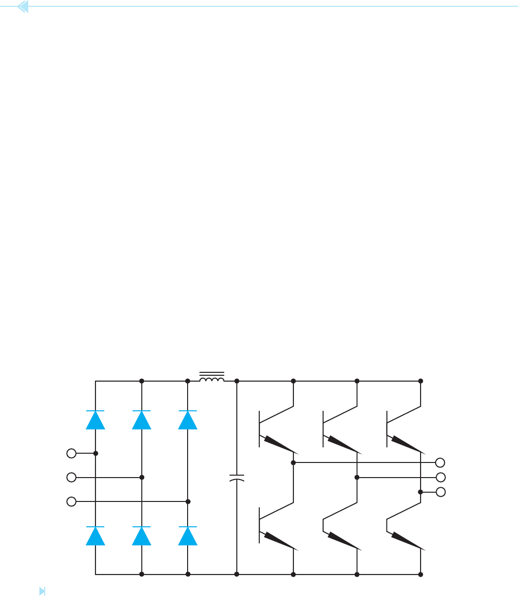
Drives using IGBTs generally use diodes to rectify
the AC voltage into DC, not SCR, Figure 13–9. The
three-phase recti er supplies a constant DC volt-
age to the transistors. The output voltage to the
motor is controlled by
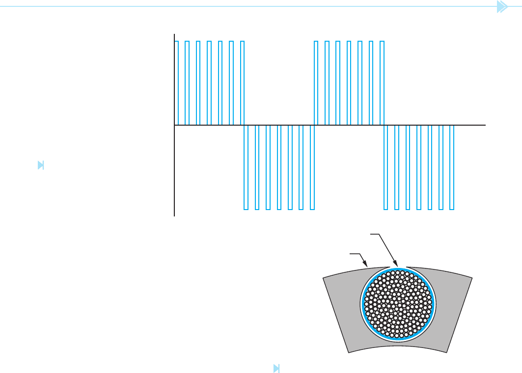
pulse width modulation
(PWM). PWM is accomplished by turning the tran-
sistor on and off several times during each half cycle,
Figure 13–10. The output voltage is an average of
the peak or maximum voltage and the amount of
time the transistor is turned on or off. Assume that
480 volts 3 phase AC is recti
ed to DC and ltered.
The DC voltage applied to the IGBTs is approxi-
mately 630 volts. The output voltage to the motor
is controlled by the switching of the transistors.
Assume that the transistor is on for 10 microsec-
onds and off for 20 microseconds. In this example
TO
MOTOR
IGBTs
CHOKE
DIODES
LINE
Figure 13–9
Variable frequency drives using IGBTs generally use diodes in the rectifi er instead of SCRs. (Source: Delmar/Cengage Learning)
UNIT 13 Multispeed Motors 141
5. The case size is larger than most three phase
motors. The case size is larger because of the
added insulating paper between the windings
and the stator core. Also, a larger case size
helps cool the motor by providing a larger
surface area for the dissipation of heat.
Variable Frequency Drives
Using SCRs and GTOs
Variable frequency drives intended to control
motors over 500 horsepower generally use SCRs
or GTOs (gate turn off device). GTOs are similar to
SCRs except that conduction through the GTO can
be stopped by applying a negative voltage, negative
with respect to the cathode, to the gate. SCRs and
frequency drives. They differ from standard motors
in several ways:
1. Many inverter rated motors contain a
separate blow to provide continuous cooling
for the motor regardless of the speed. Many
motors use a fan connected to the motor shaft
to help draw air though the motor. When
the motor speed is reduced, the fan cannot
maintain suf cient air ow to cool the motor.
2. Inverter rated motors generally have insu-
lating paper between the windings and the
stator core, Figure 13–11. The high voltage
spikes produce high currents that produce a
high magnetic eld. This increased magnetic
eld causes the motor windings to move.
This movement can eventually cause the
insulation to wear off the wire and produce
a grounded motor winding.
3. Inverter rated motors generally have phase
paper added to the terminal leads. Phase
paper is insulating paper added to the terminal
leads that exit the motor. The high voltage
spikes affect the beginning lead of a coil
much more than the wire inside the coil. The
coil is an inductor that naturally opposes a
change of current. Most of the insulation
stress caused by high voltage spikes occurs
at the beginning of a winding.
4. The magnet wire used in the construction
of the motor windings has a higher rated
insulation than other motors.
Figure 13–10
Pulse width modulation is
accomplished by turning the
voltage on and off several
times during each half cycle.
(Source: Delmar/Cengage Learning)
STATOR CORE
INSULATING PAPER
Figure 13–11
Insulating paper is between the windings
and the stator frame. (Source: Delmar/Cengage Learning)
142 SECTION 3 Motors
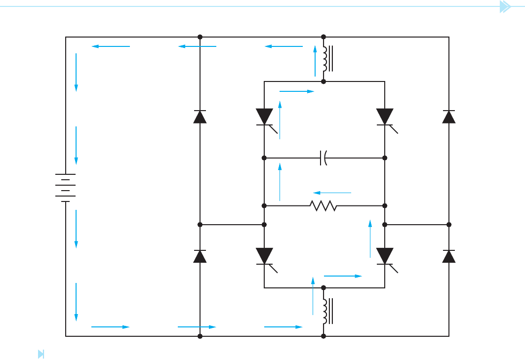
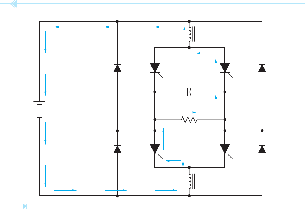
a bank of capacitors. To understand the operation
of the circuit, assume that SCRs A and A' are gated
on at the same time. Current will ow through the
circuit as shown in Figure 13–13. Notice the direc-
tion of current ow through the load, and also that
capacitor C
1
has been charged to the polarity shown.
When an SCR is gated on, it can only be turned off
by permitting the current ow through the anode-
cathode section to drop below a certain level called
the holding current level. As long as the current
continues to ow through the anode-cathode the
SCR will not turn off.
Now assume that SCRs B and B' are turned on.
Because SCRs A and A' are still turned on, two
current paths now exist through the circuit. The
positive charge on capacitor C
1
, however, causes the
negative electrons to see an easier path. The current
will rush to charge the capacitor to the opposite
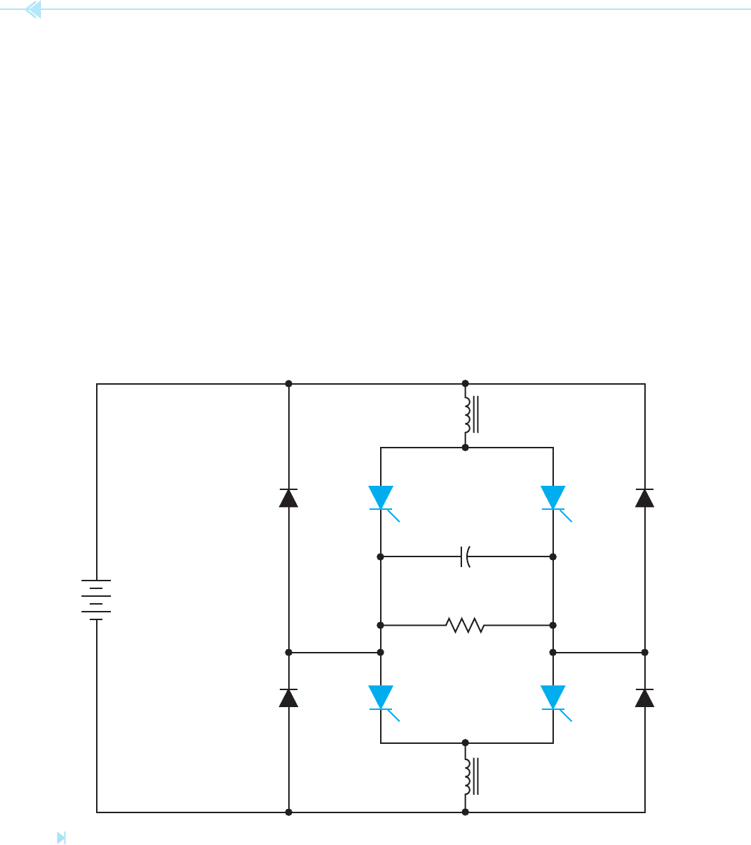
GTOs are thyristors and have the ability to handle
a greater amount of current than transistors. An
example of a single-phase circuit used to convert
DC voltage to AC voltage with SCRs is shown in
Figure 13–12. In this circuit, the SCRs are con-
nected to a control unit which controls the sequence
and rate at which the SCRs are gated on. The circuit
is constructed so that SCRs A and A' are gated on
at the same time and SCRs B and B' are gated on
at the same time. Inductors L
1
and L
2
are used for
ltering and wave shaping. Diodes D1 through D4
are clamping diodes and are used to prevent the
output voltage from becoming excessive. Capacitor
C
1
is used to turn one set of SCRs off when the other
set is gated on. This capacitor must be a true AC
capacitor because it will be charged to the alternate
polarity each half cycle. In a converter intended to
handle large amounts of power, capacitor C
1
will be
D
1
D
2
D
3
D
4
B'
LOAD
C
1
A'
L
2
AB
L
1
+
DC POWER
SUPPLY
Figure 13–12
Changing DC to AC using SCRs. (Source: Delmar/Cengage Learning)
UNIT 13 Multispeed Motors 143
is to provide speed control for an AC motor, most
drives provide functions that other types of controls
do not. Many variable frequency drives can provide
the low speed torque characteristic that is so desir-
able in DC motors. It is this feature that permits AC
squirrel-cage motors to replace DC motors for many
applications.
Many variable frequency drives also provide cur-
rent limit and automatic speed regulation for the
motor. Current limit is generally accomplished by
connecting current transformers to the input of the
drive and sensing the increase in current as load is
added. Speed regulation is accomplished by sensing
the speed of the motor and feeding this information
back to the drive.
Another feature of variable frequency drives is
acceleration and deceleration control, sometimes
polarity, stopping the current owing through SCRs
A and A' permitting them to turn off. The current
now ows through SCRs B and B' and charges the
capacitor to the opposite polarity, Figure 13–14.
Notice that the current now ows through the load
in the opposite direction, which produces alternat-
ing current across the load.
To produce the next half cycle of AC current,
SCRs A and A' are gated on again. The positively
charged side of the capacitor will now cause the
current to stop owing through SCRs B and B' per-
mitting them to turn off. The current again ows
through the load in the direction indicated in
Figure 13–14. The frequency of the circuit is deter-
mined by the rate at which the SCRs are gated on.
FEATURES OF VARIABLE FREQUENCY CONTROL. Although
the primary purpose of a variable frequency drive
D
1
D
2
D
3
D
4
B'
LOAD
+ C
1
–
A'
L
2
A B
L
1
+
DC POWER
SUPPLY
Figure 13–13
Current fl ows through SCRs A and A'. (Source: Delmar/Cengage Learning)
DESIGN SERVICES OF
144 SECTION 3 Motors
Some other adjustments that can usually be set
by changing potentiometers or programming the
unit are as follows:
Current Limit: These controls set the maxi-
mum amount of current the drive is permitted
to deliver to the motor.
Volts per Hertz: This sets the ratio by which
the voltage increases as frequency increases or
decreases as frequency decreases.
Maximum Hertz: These controls set the
maximum speed of the motor.
Minimum Hertz: This sets the minimum
speed the motor is permitted to run.
called “ramping.” Ramping is used to accelerate
or decelerate a motor over some period of time.
Ramping permits the motor to bring the load up to
speed slowly as opposed to simply connecting the
motor directly to the line. Even if the speed control
is set in the maximum position when the start
button is pressed, ramping permits the motor to
accelerate the load from zero to its maximum RPM
over several seconds. This feature can be a real
advantage for some types of loads, especially gear
drive loads. In some units the amount of accel-
eration and deceleration time can be adjusted by
setting potentiometers on the main control board.
Other units are completely digitally controlled and
the acceleration and deceleration times are pro-
grammed into the computer memory.
D
1
D
2
D
3
D
4
B'
LOAD
– C
1
+
A'
L
2
A B
L
1
+
DC POWER
SUPPLY
Figure 13–14
Current fl ows through SCRs B and B'. (Source: Delmar/Cengage Learning)

UNIT 13 Multispeed Motors 145
SUMMARY
Consequent pole motors change speed by changing the number of stator poles.
The disadvantage of consequent pole motors is that they have a wide range between
speeds.
The advantage of the consequent pole motor is that it maintains a high torque.
Consequent pole motors are generally used to operate two-speed compressors because of
their ability to maintain high torque.
Multispeed fan motors insert inductance in series with the main run winding to produce a
change of speed.
The run windings of multispeed fan motors have a high resistance so they will not
overheat when the motor slows down.
Multispeed fan motors cannot be used to operate high torque loads.
Variable frequency drives change the speed of the motor by changing the frequency of the
applied voltage.
The synchronous speed of an induction motor is the speed of the rotating magnetic eld.
Synchronous speed is determined by two factors: number of stator poles per phase, and
frequency of the applied voltage.
When the frequency to the motor is reduced, the voltage must be reduced also.
Variable frequency drives up to 500 horsepower generally use transistors to change the
DC voltage back into AC voltage.
Variable frequency drives above 500 horsepower generally use SCRs or GTOs to change
the DC voltage back into AC voltage.
Insulated gate bipolar transistors are used in many variable frequency drives because they
can be switched on or off at a faster rate.
Units employing IGBTs can produce voltage spikes on the motor as high as 1,600 volts.
Inverter rated motors are designed to operate with variable frequency drives.
Some variable frequency drives use potentiometers to change settings, and others are
digital and must have the setting programmed into the drive.
KEY TERMS
consequent pole motor multispeed AC motors silicon controlled
harmonics polarity recti ers (SCRs)
insulated gate bipolar pulse width tapped
transistors (IGBTs) modulation (PWM) two-speed compressors
variable frequency

146 SECTION 3 Motors
REVIEW QUESTIONS
1. Name two ways of changing the speed of a rotating magnetic eld.
2. How does the consequent pole motor change speed?
3. Name a disadvantage of the consequent pole motor.
4. Name an advantage of a consequent pole motor.
5. How many steps of speed are common to a multispeed fan motor?
6. Refer to Figure 13–3. Explain what would happen to motor operation if the winding
between low and medium should become open.
7. What is an advantage of the multispeed fan motor over the consequent pole motor?
8. What is a disadvantage of the multispeed fan motor when compared with the
consequent pole motor?
9. How much wire resistance is common for the run winding of most split-phase
motors?
10. How much wire resistance is common for the multispeed fan motor?
11. What is synchronous speed?
12. What is the disadvantage of a variable frequency drive unit that uses SCRs to convert
the AC voltage into DC voltage?
13. What is the disadvantage of driving a common bipolar junction transistor into
saturation?
14. What is the main advantage of the insulated grate bipolar transistor over the common
bipolar junction transistor?
15. What is an inverter rated motor?
TROUBLESHOOTING QUESTIONS
Refer to the schematic shown in Figure 13–4 to answer the following questions.
1. If the switch is set in the HI position, the thermostat will control the operation of:
A. The compressor only.
B. The fan motor only.
C. The speed of the fan motor.
D. Both the compressor and the speed of the fan motor.
2. When the switch is set in the HI position, both the fan motor and compressor operate. If
the switch is changed to the MED or LOW position, the compressor continues to operate,
but the fan motor stops. Which of the following could cause this problem?
A. The fan motor start winding is open.
B. The section of run winding between the red and blue wires is open in the fan motor.
C. The section of run winding between the blue and black wires is open in the fan motor.
D. The section of run winding between the black and white wires is open in the fan motor.

UNIT 13 Multispeed Motors 147
3. The fan motor will operate in any of its three speeds, but the compressor motor will not
start. Which of the following could cause this problem?
A. The switch is not making connection between L and C.
B. The switch is not making connection between L and LO.
C. The switch is not making connection between L and MED.
D. The switch is not making connection between L and HI.
4. If it is assumed that this unit operates on 120 volts AC, how is the neutral conductor
identi ed on the schematic shown in Figure 13–4?
A. The wire color is green.
B. The wire color is white.
C. The conductor is ribbed.
D. The conductor is plain.
5. If the unit is in operation and the overload protector should open:
A. Both the fan motor and compressor will stop operating.
B. Only the compressor will stop operating.
C. Only the fan motor will stop operating.
D. Both the fan motor and compressor will continue to operate.

148
There are three basic types of three-phase
motors. These are:
1. The squirrel-cage induction motor.
2. The wound rotor induction motor.
3. The synchronous motor.
The type of three-phase motor is determined by
the rotor or rotating member. The stator windings
for any of these motors is the same. In this unit, the
basic principles of operation for three-phase motors
will be discussed.
The principle of operation for all three-phase
motors is the
rotating magnetic eld. There
are three factors that cause the magnetic eld
to
rotate. These are:
1. The voltages of a three-phase system are
120° out of phase with each other.
OBJECTIVES
After studying this unit the student should
be able to:
List the three major types of three-
phase motors
Discuss the operating principle of a
three-phase motor
List the factors that determine
synchronous speed
Discuss the operation of dual-voltage
motors
Connect dual-voltage three-phase
motors for operation on low voltage
or high voltage
Three-Phase
Motor
Principles
UNIT 14
UNIT 14 Three-Phase Motor Principles 149
2. The three voltages change polarity at regular
intervals.
3. The arrangement of the stator windings
around the inside of the motor.
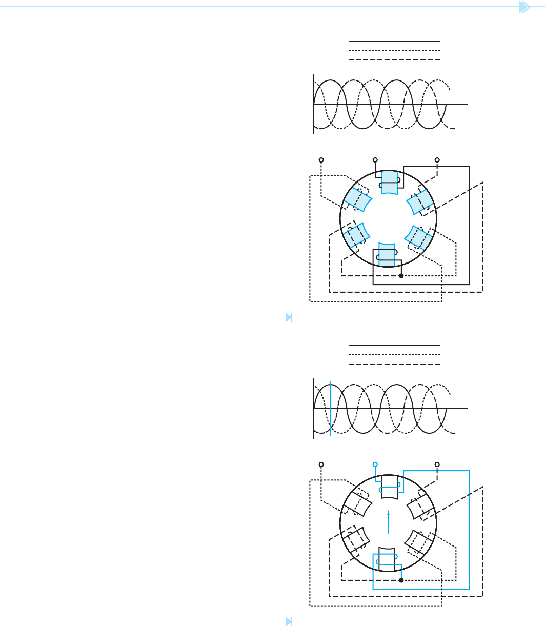
Figure 14–1A shows three AC voltages 120° out
of phase with each other, and the stator winding of
a three-phase motor. The stator illustrates a two-
pole, three-phase motor. Two-pole means that there
are two poles per phase. AC motors do not generally
have actual pole pieces as shown in Figure 14–1A,
but they will be used here to aid in understanding
how the rotating magnetic eld is created in a three-
phase motor. Notice that pole pieces 1A and 1B are
located opposite each other. The same is true for
poles 2A and 2B, and 3A and 3B. The pole pieces
1A and 1B are wound with wire that is connected to
phase one of the three-phase system. Notice also that
the pole pieces are wound in such a manner that
they will always have opposite magnetic polarities.
If pole piece 1A has a north magnetic polarity, pole
piece 1B will have a south magnetic polarity at the
same time.
The windings of pole pieces 2A and 2B are con-
nected to line 2 of the three-phase system. The
windings of pole pieces 3A and 3B are connected to
line 3 of the three-phase system. These pole pieces
are also wound in such a manner as to have the
opposite polarity of magnetism.
To understand how the magnetic eld rotates
around the inside of the motor, refer to Figure 14–1B.
Notice a line, labeled “A,” has been drawn through
the three voltages of the system. This line is used
to illustrate the condition of the three voltages
at this point in time. The arrow drawn inside
the motor indicates the greatest strength of the
magnetic field at the same point in time. It is to be
assumed that the arrow is pointing in the direction
of the north magnetic eld. Notice in Figure 14–1B,
that phase 1 is at its maximum positive peak, and
that phases 2 and 3 are less than maximum. The
magnetic eld is, therefore, strongest between pole
pieces 1A and 1B.
In Figure 14–1C, line B indicates that the voltage
of line 3 is zero. The voltage of line 1 is less than maxi-
mum positive; and line 2 is less than maximum nega-
tive. The magnetic eld at this point is concentrated
between the pole pieces of phase 1 and phase 2.
L
1
L
2
L
3
1A
2A
3A
2B
1B
3B
L
1
L
2
L
3
Figure 14–1A
Basic stator winding. (Source: Delmar/Cengage Learning)
L
1
L
2
L
3
1A
2A
3A
2B
1B
3B
L
1
L
2
L
3
A
Figure 14–1B
The magnetic fi eld is concentrated between the poles
of phase 1. (Source: Delmar/Cengage Learning)