Stephen L. Herman, Bennie Sparkman. Electricity and Controls for HVAC-R (6th edition)
Подождите немного. Документ загружается.


130 SECTION 3 Motors
The capacitor-start induction run motor develops a higher starting torque than the
resistance-start induction run motor.
The capacitor-start motor develops a higher starting torque by using the capacitor to pro-
duce a 90° phase shift between the current ow in the run winding and the current ow
in the start winding.
Maximum starting torque for the split-phase motor is produced when the run winding
current and start winding current are 90° out of phase with each other.
Permanent-split capacitor motors do not disconnect the start winding when the motor is
in operation.
Some permanent-split capacitor motors use an extra capacitor during the starting
period.
The identifying mark on an oil- lled capacitor should be connected to the line side of the
circuit.
KEY TERMS
capacitor-start
induction-run motor
capacitor-start
capacitor-run motor
centrifugal switch
permanent-split
capacitor motor (PSC)
resistance-start
induction-run motor
rotating eld speed
run winding
split-phase motor
start winding
torque
two-phase power
REVIEW QUESTIONS
1. What is a split-phase motor?
2. What are the three basic types of split-phase motors?
3. Explain the difference in construction of run windings and start windings.
4. How many degrees out of phase should the current in the start winding be with the
current in the run winding to develop maximum starting torque?
5. What type of capacitor is generally used with a capacitor start induction-run motor?
6. Can the micro-farad value of this capacitor be increased to improve starting torque?
7. What type of capacitor is used with a permanent-split capacitor motor?
8. Does the capacitor of a capacitor start induction-run motor help correct power
factor?
9. If necessary, can an AC electrolytic capacitor of higher voltage rating be used as the
starting capacitor?
10. What is a centrifugal switch used for?

The shaded-pole induction motor is another
type of AC single-phase motor used to a large extent
in the air conditioning
eld. This motor is popular
because of its simplicity and long life. The shaded-
pole motor contains no start winding or centrifugal
switch. The rotating magnetic eld is created by a
shading coil wound around one side of each pole
piece.
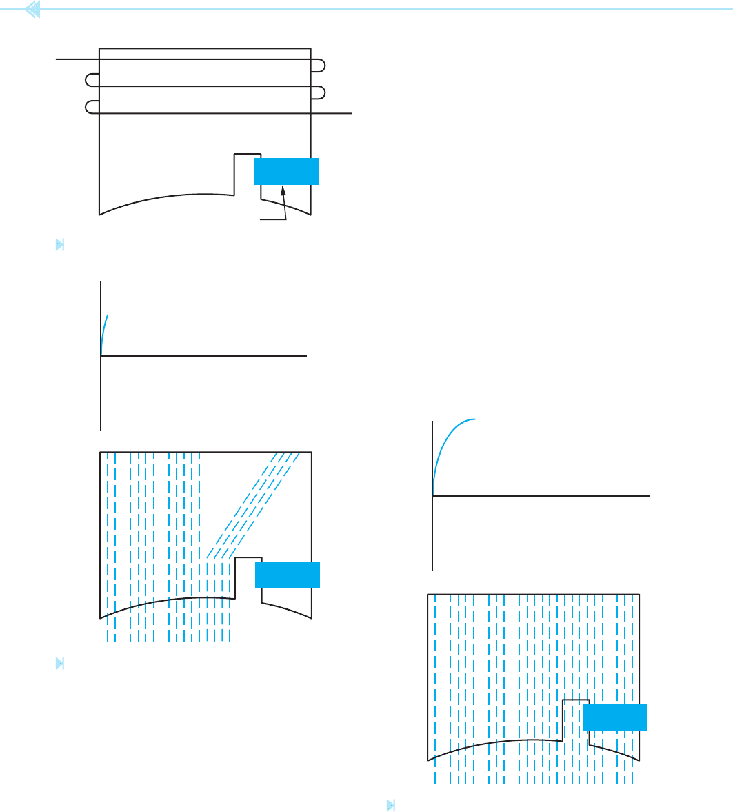
THE SHADING COIL
The shading coil is wound around one end of the
pole piece, Figure 12–1. The shading coil is actu-
ally a large loop of copper wire or a copper band.
Both ends of the loop are connected together to
form a complete circuit. The shading coil acts in
the same manner as a transformer with a shorted
secondary winding. When the voltage of the AC
The Shaded-
Pole Induction
Motor
OBJECTIVES
After studying this unit the student should
be able to:
Discuss the operation of a shaded-pole
induction motor
Defi ne a shading coil
List common uses for the shaded-pole
induction motor
131
UNIT 12
132 SECTION 3 Motors
the shading coil, there will be an opposition to the
change of magnetic ux.
When the AC voltage reaches its peak value, it is no
longer changing and there is no voltage being induced
into the shaded coil. Since there is no current ow in
the shading coil, there is no opposition to the magnetic
ux. The magnetic ux of the pole piece is now uni-
form across the pole face, Figure 12–3.
When the AC voltage begins to decrease from its
peak value back toward zero, the magnetic eld of
the pole piece begins to collapse. A current is again
induced into the shading coil. The induced current
opposes the change of magnetic ux, Figure 12–4.
This causes the magnetic ux to be concentrated in
the shaded section of the pole piece.
When the AC voltage passes through zero and
begins to increase in the negative direction, the same
set of events happen, except that the polarity of the
magnetic eld is reversed. If these events were to be
waveform increases from zero toward its positive
peak, a magnetic eld is created in the pole piece.
As magnetic lines of ux cut through the shading
coil, a voltage is induced in the coil. Because the coil
is a low-resistance short circuit, a large amount of
current ows in the loop. This current ow causes
an
opposition to the change of magnetic ux,
Figure 12–2. As long as voltage is induced into
SHADING COIL
Figure 12–1
A shaded pole.
(Source: Delmar/Cengage Learning)
0
–
+
Figure 12–2
The shading coil opposes a change of magnetic fl ux as
voltage increases. (Source: Delmar/Cengage Learning)
0
–
+
Figure 12–3
There is no opposition to magnetic fl ux when the volt-
age is not changing. (Source: Delmar/Cengage Learning)
UNIT 12 The Shaded-Pole Induction Motor 133
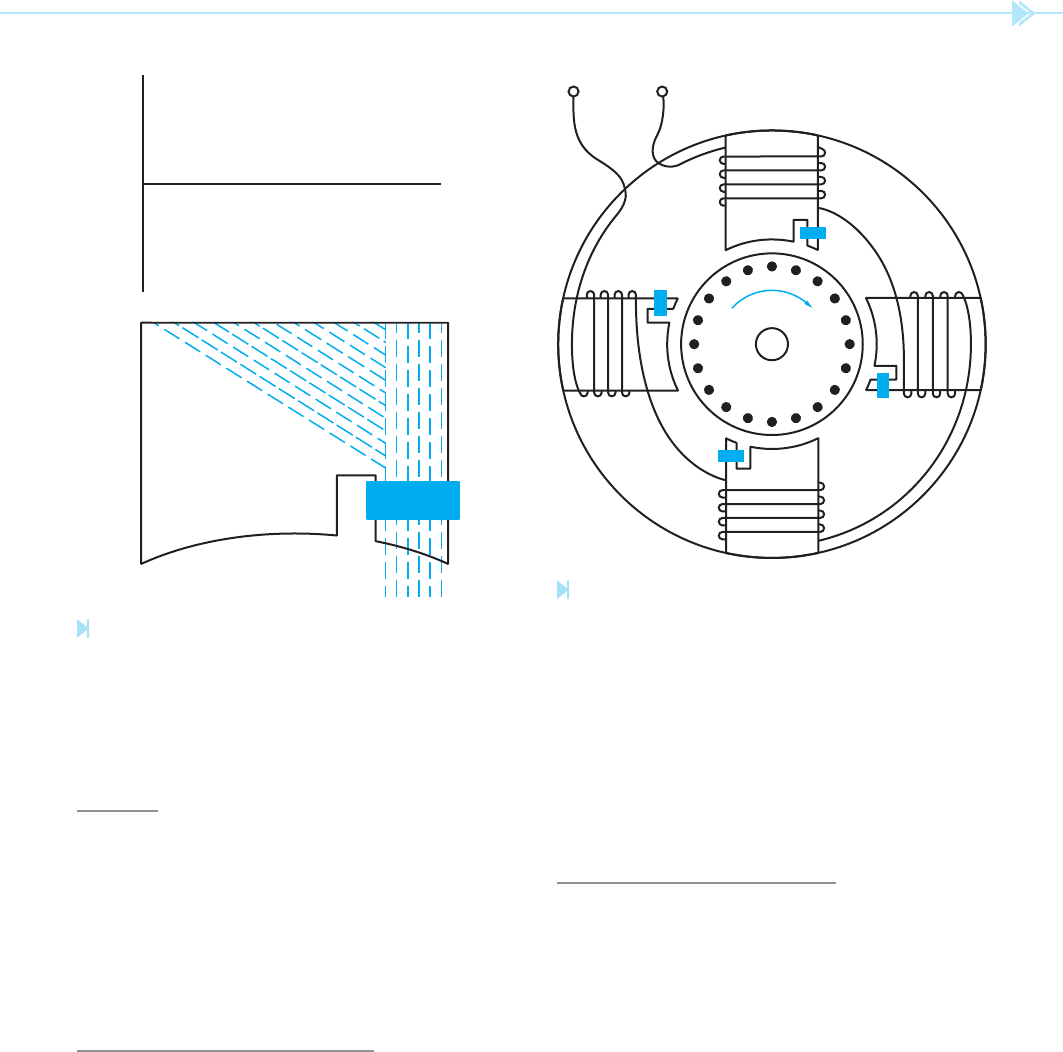
the arrow in Figure 12–5. If the direction of rotation
must be changed, it can be done by removing the
stator winding and turning it around. This is not a
common practice, however. As a general rule, the
shaded-pole induction motor is considered to be
nonreversible.
GENERAL OPERATING
CHARACTERISTICS
The shaded-pole motor contains a standard
squirrel-cage rotor. The amount of torque produced
is determined by the strength of the magnetic eld
of the stator, the strength of the magnetic eld of the
rotor, and the phase-angle difference between rotor
current and stator current. The shaded-pole motor
has a low starting torque and running torque. This
motor is generally used in applications that do not
require a large amount of starting torque, such as
fans and blowers. Figure 12–6 shows a photograph
of a shaded-pole induction motor.
seen in rapid order, it could be seen that the magnetic
eld rotates across the face of the pole piece.
SPEED
The speed of the shaded-pole induction motor is
determined by the same factors that determine
the synchronous speed of other induction motors:
frequency and number of stator poles. Shaded-pole
motors are commonly wound as four- or six-pole
motors. Figure 12–5 shows a drawing of a four-
pole motor.
REVERSING DIRECTION
OF ROTATION
The direction the magnetic eld moves across the
face of the pole piece is determined by the side of the
pole piece that has the shaded coil. The rotor will
turn in the direction of the shaded pole as shown by
0
–
+
Figure 12–4
The shading coil opposes a change of fl ux when the
voltage decreases. (Source: Delmar/Cengage Learning)
TO
AC
LINE
Figure 12–5
A four-pole shaded-pole induction motor. (Source: Delmar/
Cengage Learning)
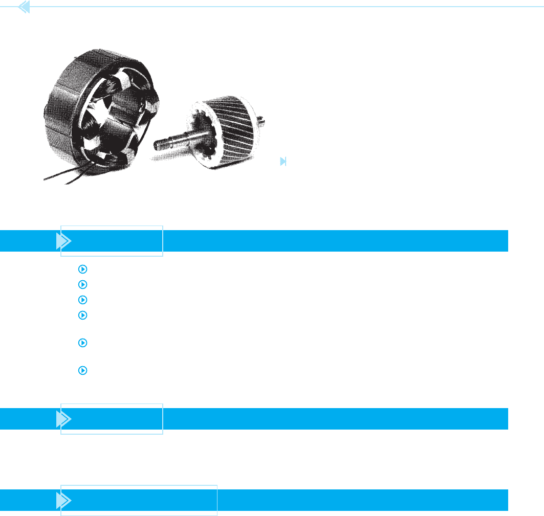
134 SECTION 3 Motors
Figure 12–6
Stator winding and rotor of a shaded-pole induction
motor.
(Courtesy of Westinghouse Electric Corp.).
SUMMARY
The shaded-pole induction motor is popular because of its simplicity and long life.
Shaded-pole induction motors do not contain a start winding or centrifugal switch.
Shaded-pole induction motors operate on the principle of a rotating magnetic eld.
A shading coil or loop is used to produce an out of phase ux across the face of the pole
piece, thus producing a rotating magnetic eld.
The speed of a shaded-pole induction motor is determined by the number of stator poles
and the frequency of the applied voltage.
Shaded-pole induction motors are generally considered to be nonreversible.
KEY TERMS
magnetic ux shaded-pole induction motor shading coil
opposition
REVIEW QUESTIONS
1. What is a shading coil?
2. What determines the synchronous speed of a shaded-pole motor?
3. In general, how is the direction of a shaded-pole induction motor reversed?
4. What type of rotor does the shaded-pole motor contain?
5. Name two advantages of the shaded-pole motor over the split-phase induction motor.

Multispeed AC motors have been used to a
great extent in the air conditioning eld for many
years. There are two basic types of multispeed
motors used. One type is known as the
conse-
quent pole motor. The other type is generally a
permanent-split capacitor motor.
THE CONSEQUENT POLE MOTOR
The speed of the rotating magnetic eld of an AC
induction motor can be changed in either of two
ways. These are:
1. Change the frequency of the AC voltage.
2. Change the number of stator poles.
The consequent pole motor changes the motor
speed by changing the number of its stator poles.
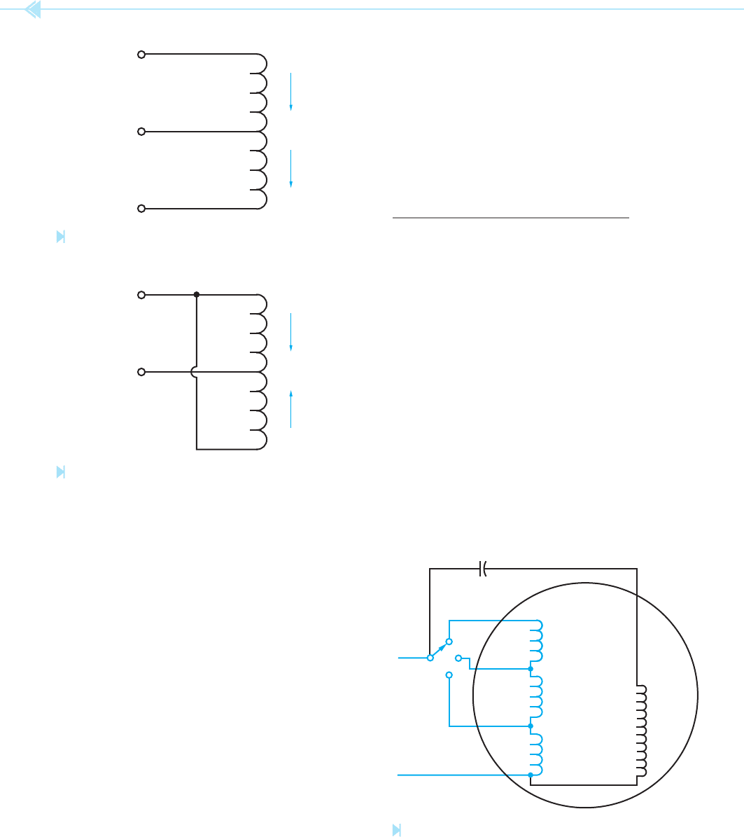
The run winding in Figure 13–1 has been
tapped
Multispeed
Motors
OBJECTIVES
After studying this unit the student should
be able to:
Discuss the operation of a consequent
pole motor
List the factors that determine the
synchronous fi eld speed of an
AC motor
Discuss the operation of multispeed
fan motors
Connect a multispeed fan motor for
operation at different speeds
135
UNIT 13
136 SECTION 3 Motors
changed by a small amount. This wide variation in
speed makes the consequent pole motor unsuitable
for some loads, such as fans and blowers.
The consequent pole motor, however, does have
some advantages over the other type of multispeed
motor. When the speed of the consequent pole motor
is reduced, its torque increases. For this reason, the
consequent pole motor can be used to operate heavy
loads, such as two-speed compressors.
MULTISPEED FAN MOTORS
Multispeed fan motors have been used in the air
conditioning industry for many years. These motors
are generally wound for two to ve steps of speed,
and are used to operate fans and squirrel-cage blow-
ers. A schematic drawing of a three-speed motor is
shown in Figure 13–3. Notice that the run winding
has been tapped to produce low, medium, and high
speed. The start winding is connected in parallel
with the run winding section. The other end of the
start lead is connected to an external oil- lled run
capacitor. This motor obtains a change in speed by
inserting inductance in series with the run winding.
The actual run winding for this motor is between
the terminals marked High and C. The windings
shown between High and Medium are connected in
series with the main run winding. When the rotary
switch is connected to the medium-speed position,
the inductive reactance of this coil limits the amount
in the center. If the AC line is connected to each end
of the winding as shown, current ows through the
winding in only one direction. Therefore, only one
magnetic
polarity is produced in the winding. If
the winding is connected as shown in Figure 13–2,
current
ows in opposite directions in each half of
the winding. Because current ows through each
half of the winding in opposite directions, the polar-
ity of the magnetic eld is different in each half of the
winding. The run winding now has two polarities
instead of one. There are now two magnetic poles
instead of one. If the windings of a two-pole motor
were to be tapped in this manner, the motor could
become a four-pole motor. The synchronous speed
of a two-pole motor is 3,600 RPM, and the synchro-
nous speed of a four-pole motor is 1,800 RPM.
The consequent pole motor has the disadvantage
of having a wide variation in speed. When the speed
is changed, it changes from a synchronous speed
of 3,600 RPM to 1,800 RPM. The speed cannot be
L
1
N
L
2
N
Figure 13–1
Center-tapped run winding.
(Source: Delmar/Cengage Learning)
L
1
S
L
2
N
Figure 13–2
Two magnetic poles are produced. (Source: Delmar/
Cengage Learning)
LOW
MED.
HIGH
COMMON
L
2
L
1
Figure 13–3
Three-speed fan motor. (Source: Delmar/Cengage Learning)
UNIT 13 Multispeed Motors 137
motor windings if the speed were to be reduced to
this extent. This motor, however, has much higher
impedance in its windings than most motors. The
run windings of most split-phase motors has a wire
resistance of 1 to 4 ohms. This motor will generally
have a resistance of 10 to 15 ohms in its run wind-
ing. It is the high impedance of the windings that
permits the motor to be operated in this manner
without damage.
Because this motor is designed to slow down
when load is added, it is not used to operate high-
torque loads. This type of motor is generally used
to operate only low-torque loads, such as fans and
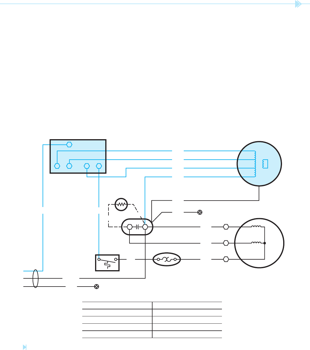
blowers. The schematic in Figure 13–4 shows a
multispeed fan motor and switch.
of current ow through the run winding. When the
current of the run winding is reduced, the strength
of the magnetic eld of the run winding is reduced
and the motor produces less torque. This causes the
motor speed to decrease.
If the rotary switch is changed to the low position,
more inductance is connected in series with the run
winding. This causes less current to ow through the
winding and another reduction in torque. When the
torque is reduced, the motor speed decreases again.
Common speeds for a four-pole motor of this
type are 1,625, 1,500, and 1,350 RPM. Notice that
this motor does not have the wide range between
speeds as the consequent pole motor does. Most
induction motors would overheat and damage the
SWITCH POSITION
LO
MED
HI
OFF
CONTACTS MADE
L to C, L to LO
L to C, L to MED
L to C, L to HI
NONE
RED
BLU
BLK
GRN
WHT
GRN
BLK
(GROUND)
LO MED
SWITCH
FAN MOTOR
COMPRESSOR
O
VERLOAD
CAPACITOR
THERMISTOR
THERMOSTAT
SERVICE CORD
HI
C
L
R
BLU
S
YELYEL
YELPLAIN
C
B
BLU
°
BLU
A
GRN
RIBBED
(GROUND)
Figure 13–4
A multispeed fan motor and switch. (Source: Delmar/Cengage Learning)
138 SECTION 3 Motors
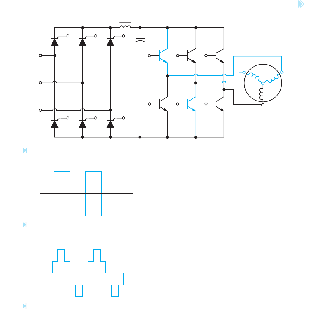
unit converts the DC voltage back into three-phase
alternating current by turning transistors on or off at
the proper time and in the proper sequence. Assume,
for example, that transistors Q1 and Q4 are switched
on at the same time. This permits stator winding T
1
to be connected to a positive voltage and T
2
to be
connected to a negative voltage. Current can ow
through Q4 to T
2
, through the motor stator winding
and through T
1
to Q1.
Now assume that transistors Q1 and Q4 are
switched off and transistors Q3 and Q6 are switched
on. Current will now ow through Q6 to stator
winding T
3
, through the motor to T
2
, and through
Q3 to the positive of the power supply.
Because the transistors are turned completely
on or completely off, the waveform produced is a
square wave instead of a sine wave, Figure 13–7.
Induction motors will operate on a square wave
VARIABLE FREQUENCY DRIVES
One of the factors that determines the speed of the
rotating magnetic eld of an AC induction motor is
the frequency of the applied voltage. If the frequency
is changed, the speed of the rotating magnetic eld
changes also. A four-pole stator will have a synchro-
nous speed (speed of the rotating magnetic eld) of
1,800 RPM when connected to a 60-Hz line. If the
frequency is lowered to 30 Hz, the synchronous
speed decreases to 900 RPM.
When the frequency is lowered, care must be
taken not to damage the stator windings. The
current ow through the winding is limited to a
great extent by inductive reactance. When the fre-
quency is lowered, inductive reactance is lowered
also (X
L
⫽ 2πFL). For this reason, variable fre-
quency drives must employ some method of lower-
ing the applied voltage to the stator as frequency is
reduced.
In the air conditioning
eld, variable frequency
drive is often used to control the speed of blower
motors. This method of controlling air ow can be
more ef cient than inserting dampers into the duct
system. Variable frequency drives are very popular
in zone controlled systems.
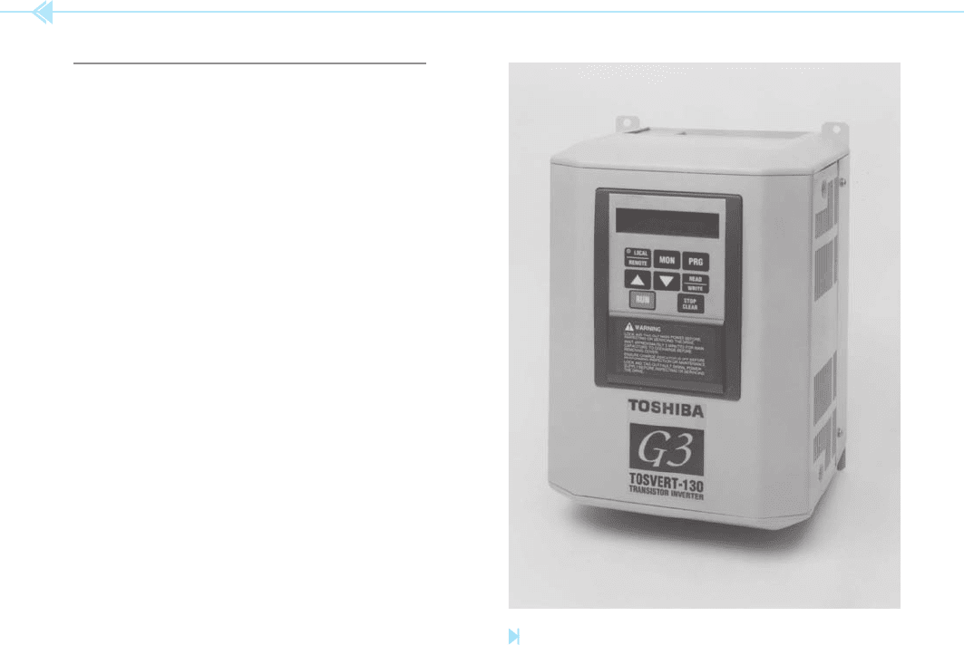
Most variable frequency drives operate by rst
changing the AC voltage into DC and then changing
it back to AC at the desired frequency. A variable fre-
quency drive is shown in Figure 13–5. There are sev-
eral methods used to change the DC voltage back into
AC. The method employed is generally determined
by the manufacturer, age of the equipment, and the
size motor the drive must control. Variable frequency
drives intended to control the speed of motors up
to 500 horsepower generally use transistors. In
the circuit shown in Figure 13–6, a three-phase
bridge changes the three-phase alternating-current
into direct current. The bridge recti er uses
SCRs
(silicon
controlled recti ers) instead of
diodes. The SCRs permit the output voltage of the
recti
er to be controlled. As the frequency decreases,
the SCRs re later in the cycle and lower the output
voltage to the transistors. A choke coil and capaci-
tor bank are used to lter the output voltage before
transistors Q1 through Q6 change the DC voltage
back into AC. An electronic control unit is connected
to the bases of transistor Q1 through Q6. The control
Figure 13–5
Variable frequency drive. (Courtesy of Toshiba Corp.).
UNIT 13 Multispeed Motors 139
Some Related Problems
The circuit illustrated in Figure 13–6 employs the
use of SCRs in the power supply and junction
transistors in the output stage. SCR power supplies
control the output voltage by chopping the incom-
ing waveform. This can cause harmonics on the
line that cause overheating of transformers and
motors, and can cause fuses to blow and circuit
breakers to trip. When bipolar junction transistors
are employed as switches, they are generally driven
into saturation by supplying them with an exces-
sive amount of base-emitter current. Saturating
the transistor causes the collector-emitter voltage
to drop to between 0.04 and 0.03 volts. This small
voltage drop allows the transistor to control large
amounts of current without being destroyed. When
a transistor is driven into saturation, however, it
cannot recover or turn off as quickly as normal.
This greatly limits the frequency response of the
transistor.
IGBTs
Many transistor-controlled variable drives now
employ a special type of transistor called an insu-
lated gate bipolar transistor (IGBT). IGBTs
MOTOR
+
–
Q1
Q2
T
1
Q3
Q4
T
2
Q5
Q6
T
3
L1
L2
L3
Figure 13–6
Variable frequency drive using bipolar transistor to change the direct current back into alternating current.
(Source: Delmar/Cengage Learning)
Figure 13–7
Square wave. (Source: Delmar/Cengage Learning)
Figure 13–8
Stepped wave.
(Source: Delmar/Cengage Learning)
without much of a problem. Some manufacturers
design units that will produce a stepped waveform
as shown in Figure 13–8. The stepped waveform is
used because it closely approximates a sine wave.