Stephen L. Herman, Bennie Sparkman. Electricity and Controls for HVAC-R (6th edition)
Подождите немного. Документ загружается.

100 SECTION 2 Control Circuits
Notice that the overload contact is connected
in series with the motor starter coil. If the overload
contact should open, it has the same effect as press-
ing the stop button. The fuse is connected in series
with both the control circuit and the motor. If the
fuse should open, it has the effect of disconnecting
power from the line.
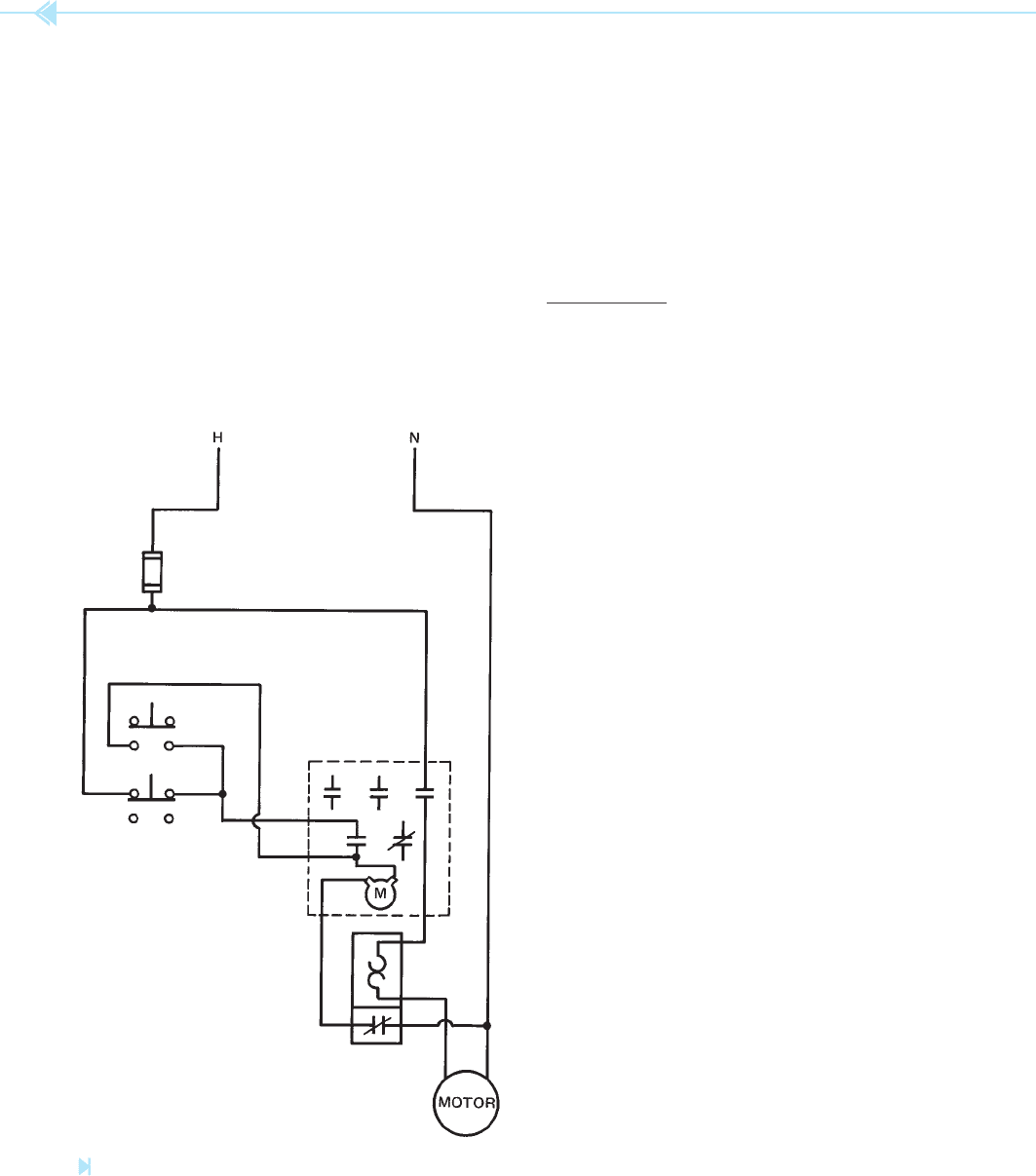
A wiring diagram for the start-stop pushbut-
ton circuit is shown in Figure 9–17. Although this
diagram looks completely different, it is electrically
the same as the schematic diagram. Notice the push
button symbols indicate double-acting push buttons.
The stop button, however, uses only the normally
closed section and the start button uses only the
Figure 9–17
Wiring diagram of start-stop pushbutton control circuit.
(Source: Delmar/Cengage Learning)
normally open section. The motor starter shows
three load contacts and two auxiliary contacts. One
auxiliary contact is open and one is closed. Notice
that only the open contact has been used.
The overload unit shows two different sections.
One section contains the thermal heater element
connected in series with the motor, and the nor-
mally closed contact is connected in series with the
coil of the M-motor starter.
EXAMPLE
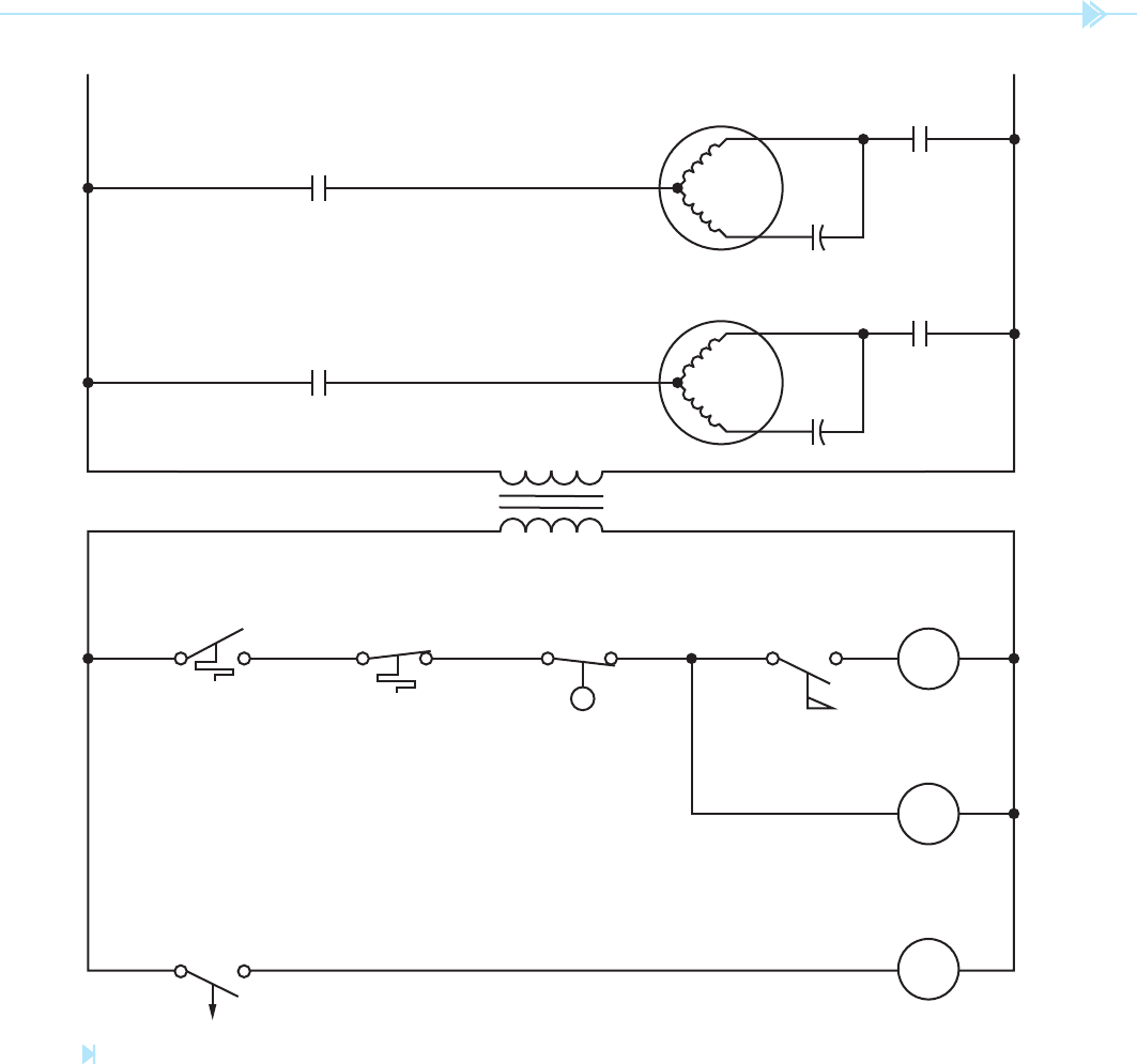
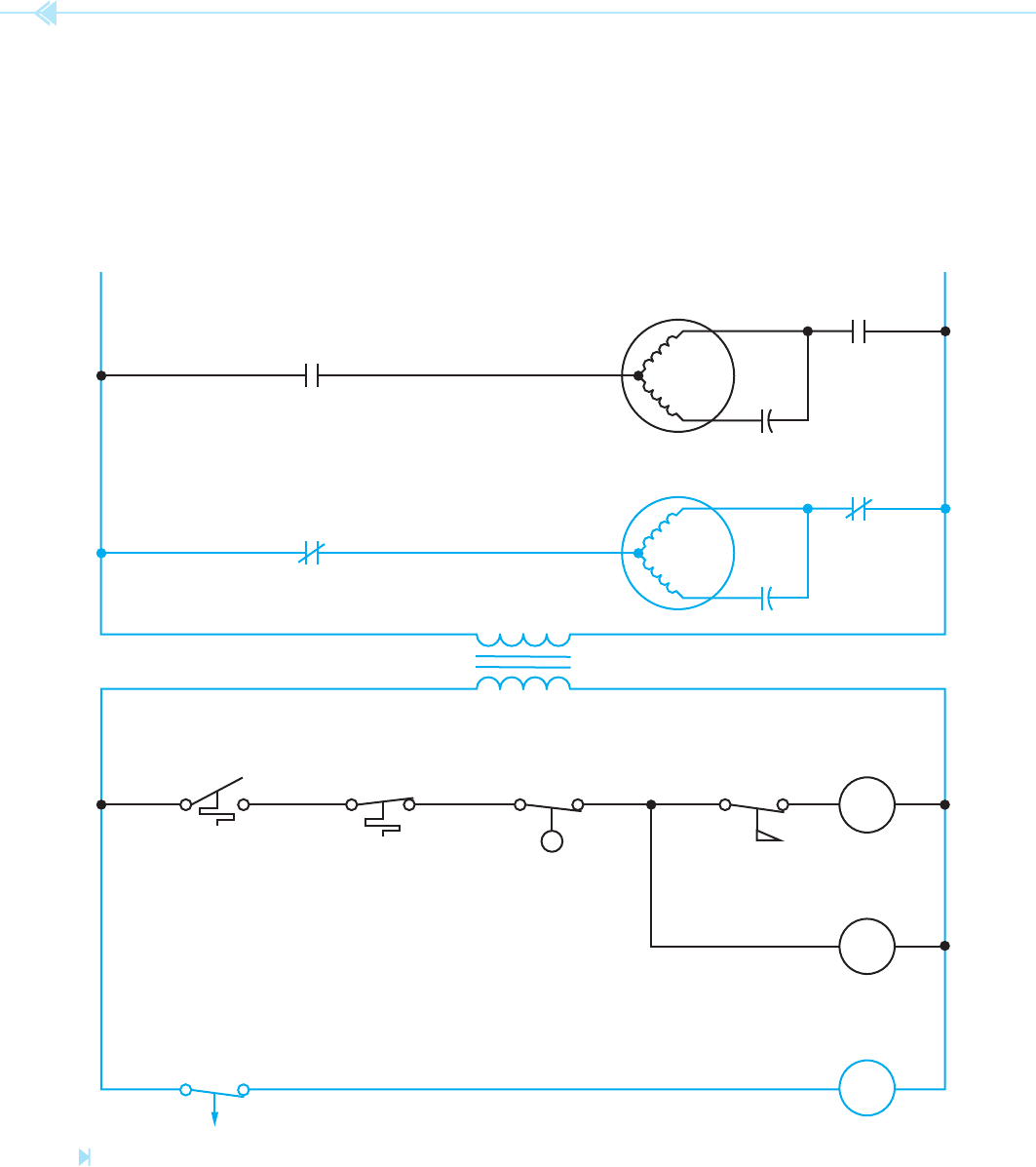
The circuit shown in Figure 9–18 controls the oper-
ation of an oil- red boiler. A high pressure pump
motor is used to inject fuel oil into a combustion
chamber where it is burned. A blower motor is used
to supply combustion air to the chamber. The circuit
will not permit fuel oil to be injected into the cham-
ber unless the blower motor is operating. The circuit
also permits the blower motor to continue operation
for a period of one minute after the thermostat is
satis ed. This permits any residual smoke or fumes
to be removed from the combustion chamber.
The rst step in understanding the operation
of the circuit is to examine the components and
determine what they control. The thermostat is a
normally closed held open switch. It is normally
closed because the movable contact is drawn above
the stationary contact. The movable contact is
not making connection to the stationary contact,
however. This indicates that the contact is being
held open. The thermal symbol indicates that the
contact is controlled by temperature. The thermal
symbol represents a bimetal helix. An increase in
temperature causes the helix to expand and push
upward on the contact. A decrease in temperature
causes the helix to contract. If the helix contracts
enough, the movable contact will make connection
with the stationary contact and close the switch.
This thermostat symbol indicates that an increase of
temperature will open the switch and a decrease of
temperature will close the switch. This is the normal
operation of a heating thermostat.
The high temperature switch is a thermally acti-
vated switch also. The switch is shown normally
closed. If the temperature should increase high
enough, the switch will open and break connection
to the high pressure pump motor relay and time
delay relay.
UNIT 9 Schematics and Wiring Diagrams 101
The low water switch is a normally open held
closed switch. The switch is normally open because
the movable contact is drawn below the stationary
contact. Because the movable contact is touching
the station contact it is being held closed. This switch
is drawn to indicate that a drop in liquid level will
cause the switch contacts to open and break the cir-
cuit to the high pressure pump motor relay and time
HPM
HPM
L2
HIGH PRESSURE PUMP
L1
BMR
THERMOSTAT
BMRBLOWER MOTOR
HIGH
TEMPERATURE
LOW
WATER
HP
PUMP
RELAY
FLOW
TRANSFORMER 240/24
HPM
OFF DELAY
TIMER 1 MINUTE
BLOWER
MOTOR
RELAY
BMR
TDR
TDR
Figure 9–18
Boiler control circuit. (Source: Delmar/Cengage Learning)
delay relay. One of the most dangerous conditions for
a boiler is a low water level. If the water level should
drop below a preset point, the switch will open.
The ow switch is normally open. A ow of air
causes the switch contacts to close. The ow switch
is used to insure that there is a ow of combustion
air into the combustion chamber before fuel oil is
injected into the chamber.
102 SECTION 2 Control Circuits
The time delay contact (TDR) is connected in
series with the blower motor relay coil. The symbol
indicates that the timer is an off delay timer. The
arrow always points in the direction the contacts
will move after the delay period. The arrow indicates
that the contacts will delay reopening after they
have changed position.
HPM
HPM
L2
HIGH PRESSURE PUMP
L1
BMR
THERMOSTAT
BMRBLOWER MOTOR
HIGH
TEMPERATURE
LOW
WATER
HP
PUMP
RELAY
FLOW
TRANSFORMER 240/24
HPM
OFF DELAY
TIMER 1 MINUTE
BLOWER
MOTOR
RELAY
BMR
TDR
TDR
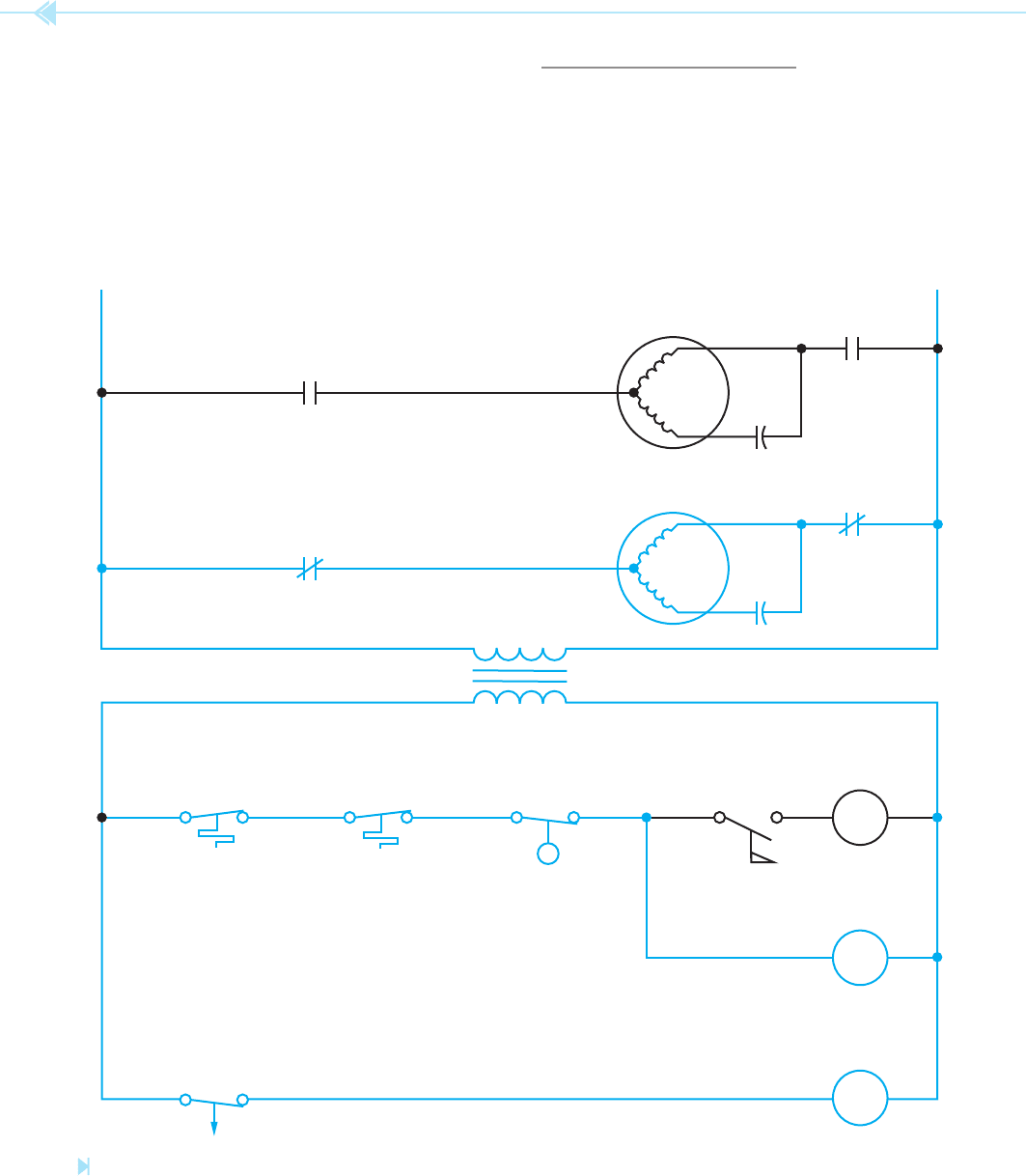
CIRCUIT OPERATION
When the thermostat contact closes, a circuit is
completed through the closed high temperature
switch, low water switch, and coil of the time delay
relay. Since the timer is an off delay timer, TDR
contacts close immediately and energize the blower
motor relay, Figure 9–19. This causes the BMR
Figure 9–19
The thermostat contacts close. (Source: Delmar/Cengage Learning)
UNIT 9 Schematics and Wiring Diagrams 103
high pressure pump to the line. The circuit is now in
full operation. The circuit will continue to operate in
this manner until the thermostat contacts reopen,
Figure 9–21. When the thermostat contacts reopen,
power is disconnected from the high pressure pump
motor relay and the time delay relay. Because the
contacts to close and connect the blower motor to
the power line.
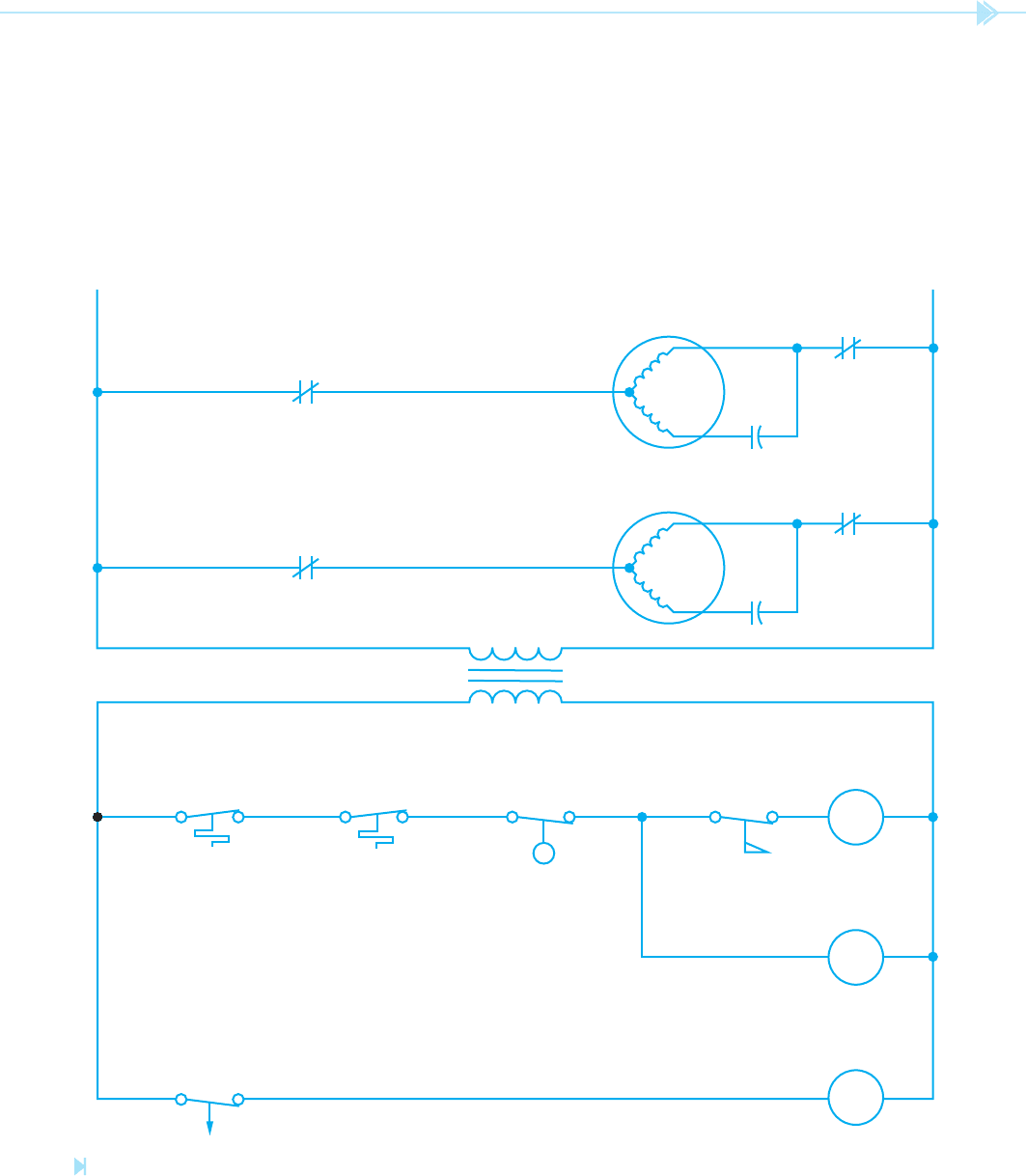
The air ow produced by the blower motor causes
the ow switch to close and energize the coil of the
high pressure pump motor relay, Figure 9–20. This
causes the HPM contacts to close and connect the
Figure 9–20
The circuit is in full operation. (Source: Delmar/Cengage Learning)
HPM
HPM
L2
HIGH PRESSURE PUMP
L1
BMR
THERMOSTAT
BMRBLOWER MOTOR
HIGH
TEMPERATURE
LOW
WATER
HP
PUMP
RELAY
FLOW
TRANSFORMER 240/24
HPM
OFF DELAY
TIMER 1 MINUTE
BLOWER
MOTOR
RELAY
BMR
TDR
TDR
104 SECTION 2 Control Circuits
time delay relay is an off delay timer, it does not
start timing until the coil is deenergized. The TDR
contacts will remain closed for a period of 1 minute
before reopening. This permits the blower motor to
remove any smoke and fumes from the combustion
chamber. When the TDR contacts open, the circuit
is back in its original state as shown in Figure 9–18.
If the high temperature switch or low water switch
should open, it would have the same effect as open-
ing the thermostat.
HPM
HPM
L2
HIGH PRESSURE PUMP
L1
BMR
THERMOSTAT
BMRBLOWER MOTOR
HIGH
TEMPERATURE
LOW
WATER
HP
PUMP
RELAY
FLOW
TRANSFORMER 240/24
HPM
OFF DELAY
TIMER 1 MINUTE
BLOWER
MOTOR
RELAY
BMR
TDR
TDR
Figure 9–21
The thermostat contacts open. (Source: Delmar/Cengage Learning)
UNIT 9 Schematics and Wiring Diagrams 105
SUMMARY
Schematics and wiring diagrams are the written language of control systems.
Motor control symbols are generally drawn to pictorially represent their function.
The way a motor control symbol is drawn indicates how it is to be connected in a circuit.
Schematic diagrams show components in their electrical sequence without regard for
physical location.
Wiring diagrams show a pictorial representation of the circuit with connecting wires.
Schematics and wiring diagrams always show the circuit in its deenergized or off position.
KEY TERMS
load
movable contact
National Electrical
Manufacturers
Association (NEMA)
node
normally closed
normally open
schematics
stationary contact
three-wire control circuits
two-wire control circuit
wiring diagrams
REVIEW QUESTIONS
1. What are the two basic types of motor controls?
2. De ne a schematic diagram.
3. De ne a wiring diagram.
4. Components used for the function of stop are generally wired _________________
and connected in _________________.
5. Components used for the function of start are generally wired _________________
and connected in _________________.
6. When reading a schematic diagram, are the components shown in their energized or
deenergized position?
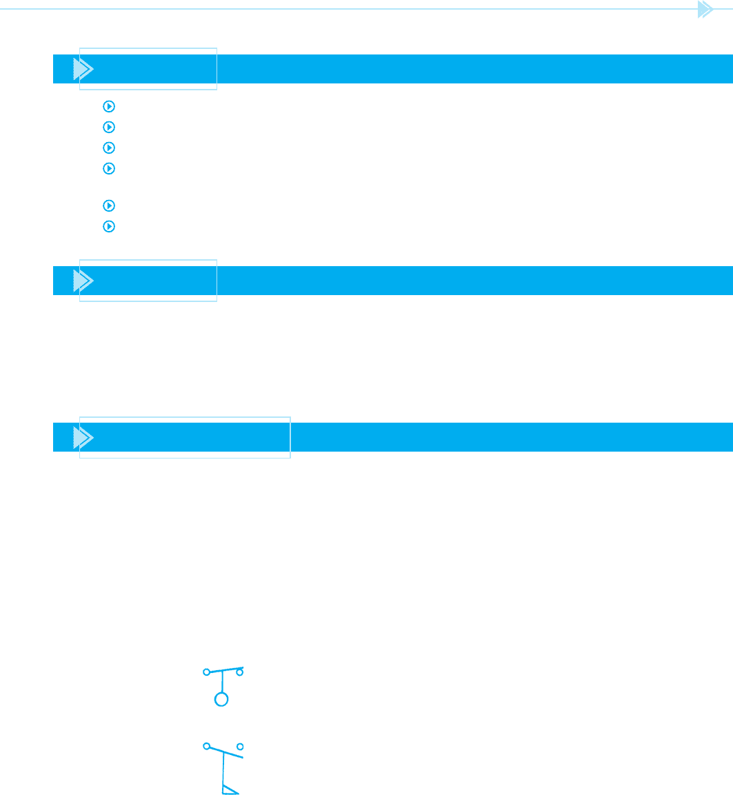
7. What does this symbol represent?
8. What does this symbol represent?
9. What does a dashed line drawn between components represent?

106 SECTION 2 Control Circuits
10. What is an auxiliary contact?
11. Make a schematic drawing of a cooling thermostat that turns on the coil of a con-
tactor. Label the contactor CC, which stands for compressor contactor. Make sure
that the circuit is drawn so that an increase in temperature will cause the contact to
close.
12. Draw a schematic that controls the operation of a sump pump. A oat switch is used
to turn the pump on when the water rises to a high enough level. It is assumed that
the oat switch has contacts rated high enough to control the motor without the use
of a relay.
13. Draw a schematic diagram for a low water level alarm. A oat switch is used to detect
the level of water in a tank. If it should fall below a predetermined level, a warning
light will come on and an alarm will sound.
14. Draw a circuit for a low pressure cutoff switch. If the pressure falls below a certain
level, it will cause a contactor coil to be disconnected. Label the contactor CC.
15. Add a thermal switch to the circuit in question 14. The switch is to be installed so that
a rise in temperature will disconnect the contactor coil.

107
In this unit, two schematic diagrams are discussed,
including their operation and development into
wiring diagrams. Developing a wiring diagram from
a schematic is the same basic procedure that is
followed when installing a control system. Under-
standing this process is also a great advantage when
troubleshooting existing circuits.
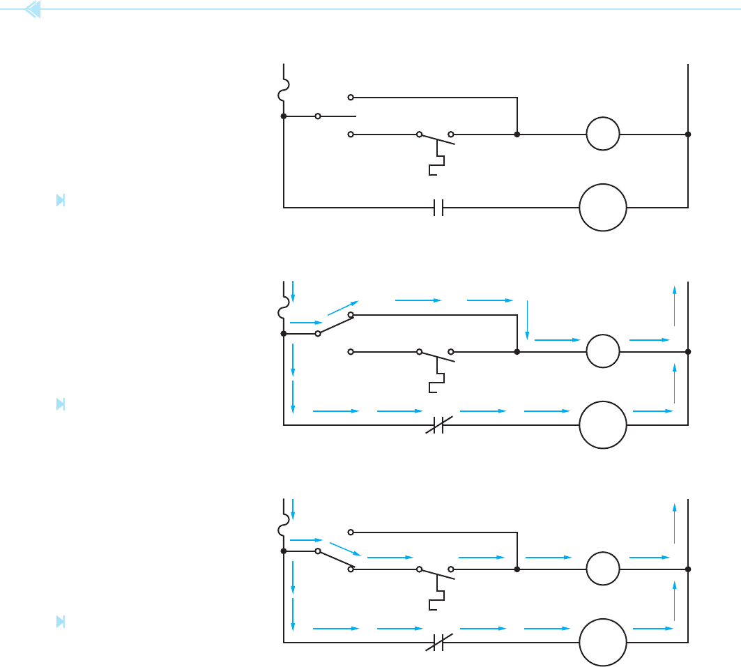
DEVELOPING CIRCUIT 1
The rst circuit discussed is shown in Figure 10–1.
In this circuit, a fan motor is controlled by relay
FR (fan relay). The circuit is so designed that a
switch can be used to turn the circuit completely
off, operate the fan manually, or permit the fan
to be operated by a thermostat. If the control
switch is moved to the “MAN” position as shown in
Figure 10–2, a complete circuit is provided to the
OBJECTIVES
After studying this unit the student should
be able to:
Discuss the operation of an electric
circuit by interpreting a schematic
diagram
Place wire numbers on a schematic
diagram and develop a wiring
diagram from the schematic
Developing
Wiring
Diagrams
UNIT 10
108 SECTION 2 Control Circuits
fan relay coil. Then the relay energizes, FR contact
closes and connects the motor to the line. This set-
ting permits the fan to be operated at any time,
regardless of the condition of the thermostat.
If the control switch is moved to the “AUTO”
position as shown in Figure 10–3, the fan will be
controlled by the action of the thermostat. When
the temperature increases to a predetermined level,
the thermostat contact will close. This completes a
circuit to FR coil. When FR coil energizes, the FR
contact closes and connects the fan motor to the
line. When the temperature decreases suf ciently,
the thermostat contact opens and breaks the circuit
to FR coil. When FR coil deenergizes, FR contact
opens and disconnects the motor from the line.
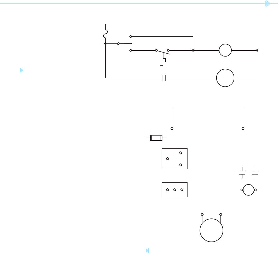
This schematic will now be developed into a wir-
ing diagram. To aid in the connection of this circuit,
a simple numbering system will be used. To use
L
1
N
FR
MOTOR
MAN
FUSE
OFF
AUTO
FR
Figure 10–1
Fan control circuit. (Source: Delmar/
Cengage Learning)
Figure 10–2
Fan relay coil is energized by
control switch. (Source: Delmar/Cengage
Learning)
L
1
N
FR
MOTOR
MAN
FUSE
OFF
AUTO
FR
Figure 10–3
Fan relay is controlled by the
thermostat. (Source: Delmar/Cengage
Learning)
L
1
N
FR
MOTOR
MAN
FUSE
OFF
AUTO
FR
UNIT 10 Developing Wiring Diagrams 109
correspond to the numbers in the schematic. For
example, the fuse in the schematic is shown with
a 1 on one side and a 2 on the other side. The fuse
in the wiring diagram is shown with a 1 on one
side and a 2 on the other side. Notice the OFF-
MANUAL-AUTOMATIC switch shown on the sche-
matic. The common terminal is numbered 2, the
this numbering system, the following rules will be
followed:
1. All components connected to the same line
will receive the same number.
2. Any time a component is gone through, the
number will change.
3. A set of numbers can be used only once.
Figure 10–4 shows the numbers placed on the
schematic. Notice that a 1 is placed at the incom-
ing power line and a 1 is also placed at one side
of the fuse. Because the fuse is a component, the
number must change on the other side of it. There-
fore, the fuse has a 2 on the other side. There is
also a 2 placed beside the common terminal of the
OFF-MANUAL-AUTOMATIC switch, and a 2 placed
beside one side of FR contact. Notice that all of these
components have the same number because there is
no break between them.
The AUTO side of the switch has been numbered 3,
and one side of the thermostat has also been
numbered 3. The other side of the thermostat is num-
bered 4, the MAN side of the switch is number 4, and
one side of FR coil is numbered 4. The other side of the
coil has been numbered 5, the neutral line is num-
bered 5, and one side of the motor is numbered 5. The
other side of the motor is numbered 6, and the other
side of FR contact is numbered 6.
Notice that all the points that are electrically con-
nected together have the same number. Notice also
that no set of numbers was used more than once.
The components of the system are shown in
Figure 10–5. Notice that numbers have been
placed beside certain components. These numbers
L
1
N
FR
MOTOR
MAN
FUSE
OFF
AUTO
FR
1
1
2
2
3
34
4
26 6 5
54
5
Figure 10–4
Schematic is numbered to aid in
connection of the circuit. (Source:
Delmar/Cengage Learning)
L
1
MOTOR
1
12
6
FR
45
6
2
5
N
5
C
A
2
3
M 4
NC C
THERMOSTAT
NO
43
Figure 10–5
Circuit components are numbered with the same
numbers that appear on the schematic. (Source: Delmar/
Cengage Learning)