Stephen L. Herman, Bennie Sparkman. Electricity and Controls for HVAC-R (6th edition)
Подождите немного. Документ загружается.

120 SECTION 3 Motors
Resistance-Start Induction-Run
Motor
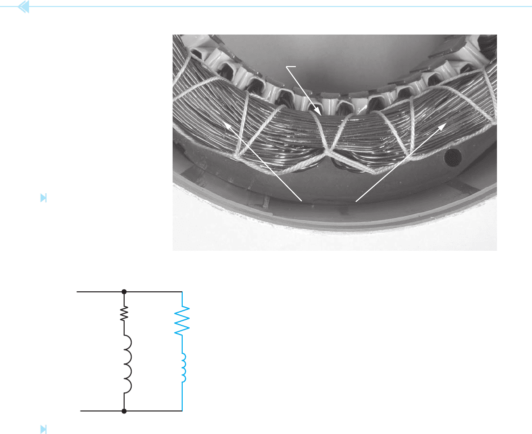
The rotating magnetic eld of the resistance-start
induction-run motor is produced by the out-of-phase
currents in the run and start windings. Since the
run winding appears more inductive and less resis-
tive than the start winding, the current ow in the
run winding will be close to 90 degrees out-of-phase
with the applied voltage. The start winding appears
more resistive and less inductive than the run wind-
ing, causing the start winding’s current to be less
out-of-phase with the applied voltage, as shown in
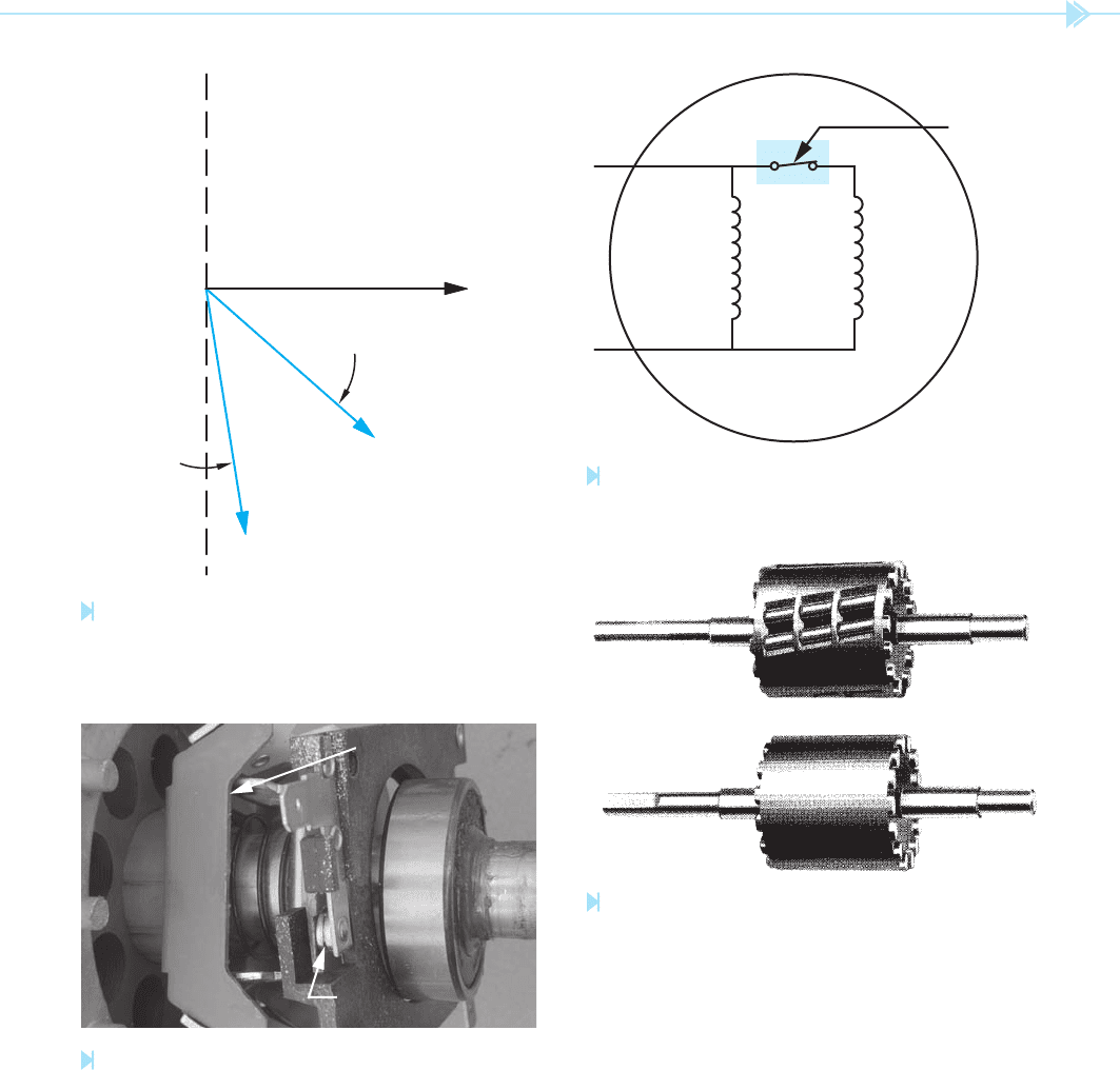
Figure 11–5. The phase-angle difference between
current in the run winding and current in the start
winding of a resistance-start induction-run motor is
generally 35 to 40 degrees. This is enough phase-
angle difference to produce a weak rotating eld,
and consequently a weak torque, to start the motor.
Once the motor reaches about 75% of its rated
speed, the start winding is disconnected from the
circuit and the motor continues to operate on the
run winding. In nonhermetically sealed motors,
the start winding is generally disconnected with a
centrifugal switch. A centrifugal switch is shown in
Figure 11–6. The contacts of the centrifugal switch
are connected in series with the start winding, as
Start Winding
Run Winding
Start
Winding
Run
Winding
Figure 11–3
Stator winding of a
resistance-start induction-run
or capacitor-start induction-
run motor. (Source: Delmar/
Cengage Learning)
Figure 11–4
The run winding has more inductance and less
resistance than the start winding. The start winding
has more resistance and less inductance than the
run winding. (Source: Delmar/Cengage Learning)
manner to produce a phase shift between the cur-
rent owing through the run winding and the
current owing through the start winding. Both
the resistance-start and capacitor-start induction-
run motors start rotation by producing a rotating
magnetic eld in the stator winding. Recall that a
rotating magnetic eld cannot be produced with a
single phase.
UNIT 11 Split-Phase Motors 121
causing the contacts to open and disconnect the
start winding from power. The motor continues to
operate on the run winding.
When the start winding is disconnected from the
circuit, a rotating magnetic eld is no longer pro-
duced in the stator. This type of motor continues to
operate because of current inducted in the squirrel
cage windings in the rotor. Squirrel cage rotors are
so named because they contain bars inside the rotor
that would resemble a squirrel cage if the lamina-
tions were removed, as shown in Figure 11–8.
Figure 11–5
The run winding current and start winding current of a
resistance-start induction-run motor will generally be
between 35 and 40 degrees out-of-phase with each other.
(Source: Delmar/Cengage Learning)
Figure 11–6
A centrifugal switch is used to disconnect the start wind-
ings when the motor reaches about 75% of rated speed.
(Source: Delmar/Cengage Learning)
Figure 11–7
The centrifugal switch contacts are connected in series
with the start winding. (Source: Delmar/Cengage Learning)
Figure 11–8
Squirrel cage rotor. (Courtesy of Bodine Electric Co.).
Start Winding
Current
Voltage
Run Winding
Current
39°
Counter Weight
Contacts
shown in Figure 11–7. When the motor is at rest or
not running, the contacts of the centrifugal switch
are closed and provide a circuit to the start winding.
When the motor is started and reaches about 75%
of its rated speed, a counterweight on the centrifugal
switch moves outward because of centrifugal force,
Run
Winding
Start
Winding
Centrifugal
Switch
122 SECTION 3 Motors
A squirrel cage is a device that is often placed inside
the cage of small pets such as hamsters to permit
them to exercise by running inside the squirrel
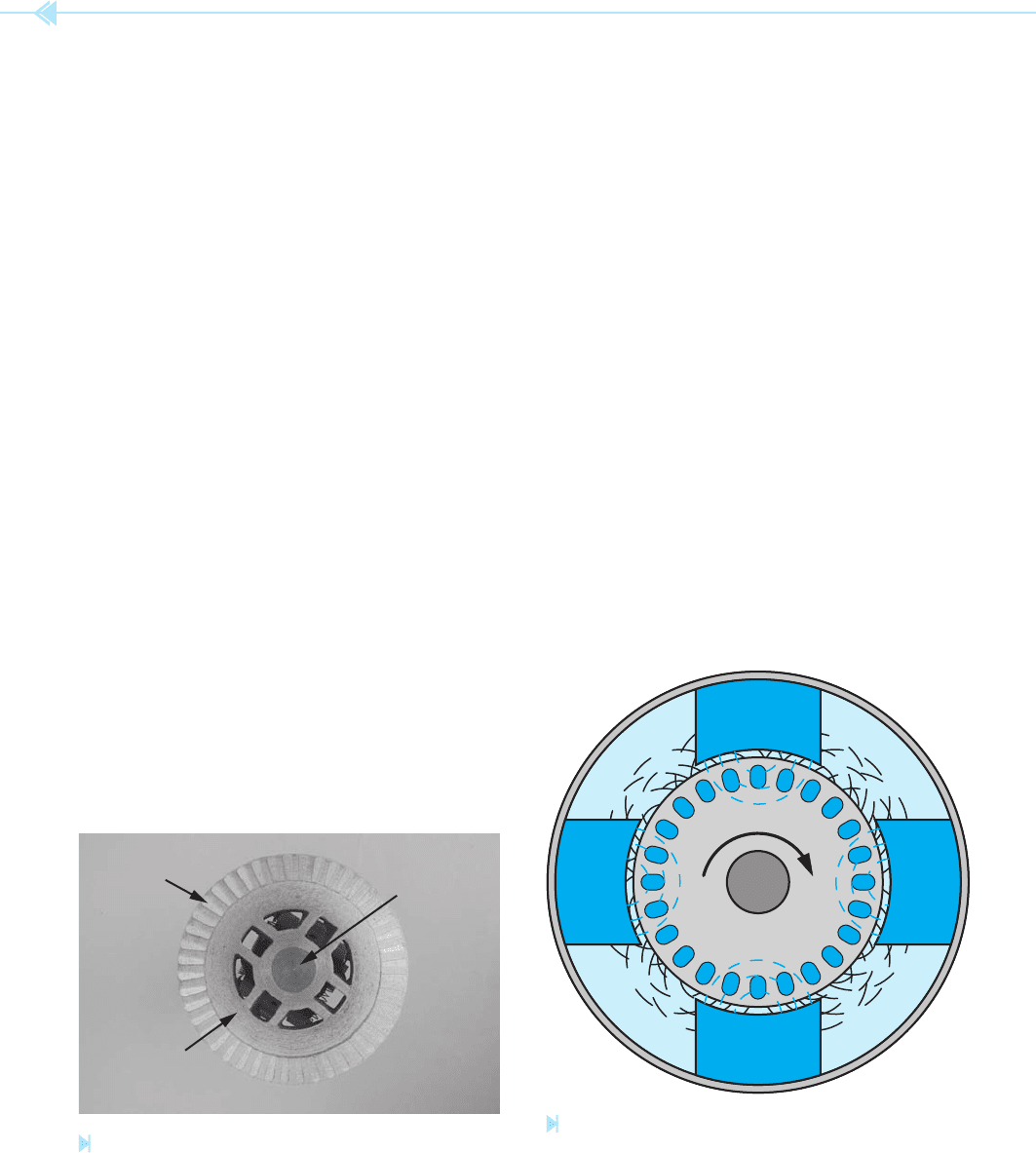
cage. A squirrel cage rotor that has been cut in half
clearly shows the bars and motor shaft, as shown in
Figure 11–9. The bars of the turning squirrel cage
rotor winding cut through lines of magnetic ux,
causing an induced voltage in the rotor. Since the
rotor bars are shorted together at each end, current
ow through the rotor bars produces a magnetic
eld in the rotor. Alternate magnetic elds are
produced in the rotor, causing the motor to con-
tinue operating, as shown in Figure 11–10. This
is the same principle that permits a three-phase
motor to continue operating if one phase is lost
and the motor is connected to single-phase power.
The main difference is that the split-phase motor is
designed to operate in this condition and the three-
phase motor is not. Resistance-start and capacitor-
start induction-run motors are rugged and will
provide years of service with little maintenance.
Their operating characteristics, however, are not
as desirable as those of other types of single-phase
motors. Due to the way they operate, they have a
low power factor. They will draw almost as much
current when the motor is running at no load as
they will when the motor is running at full load.
Typically, if the motor has a full-load current draw
of 8 amperes, the no-load current may be 6.5 to
7 amperes.
Core Material
Rotor Bars
Shaft
S
N
S
N
N
S
N
S
Figure 11–10
The rotor continues to turn because of magnetic fi elds
produced by the current induced in the rotor of the
motor.
(Source: Delmar/Cengage Learning)
Figure 11–9
Bars and shaft of a squirrel cage rotor.
(Source: Delmar/
Cengage Learning)
Capacitor-Start Induction-Run
Motors
Capacitor-start induction-run motors are very simi-
lar to resistance-start induction-run motors. The
design of the stator winding is basically the same.
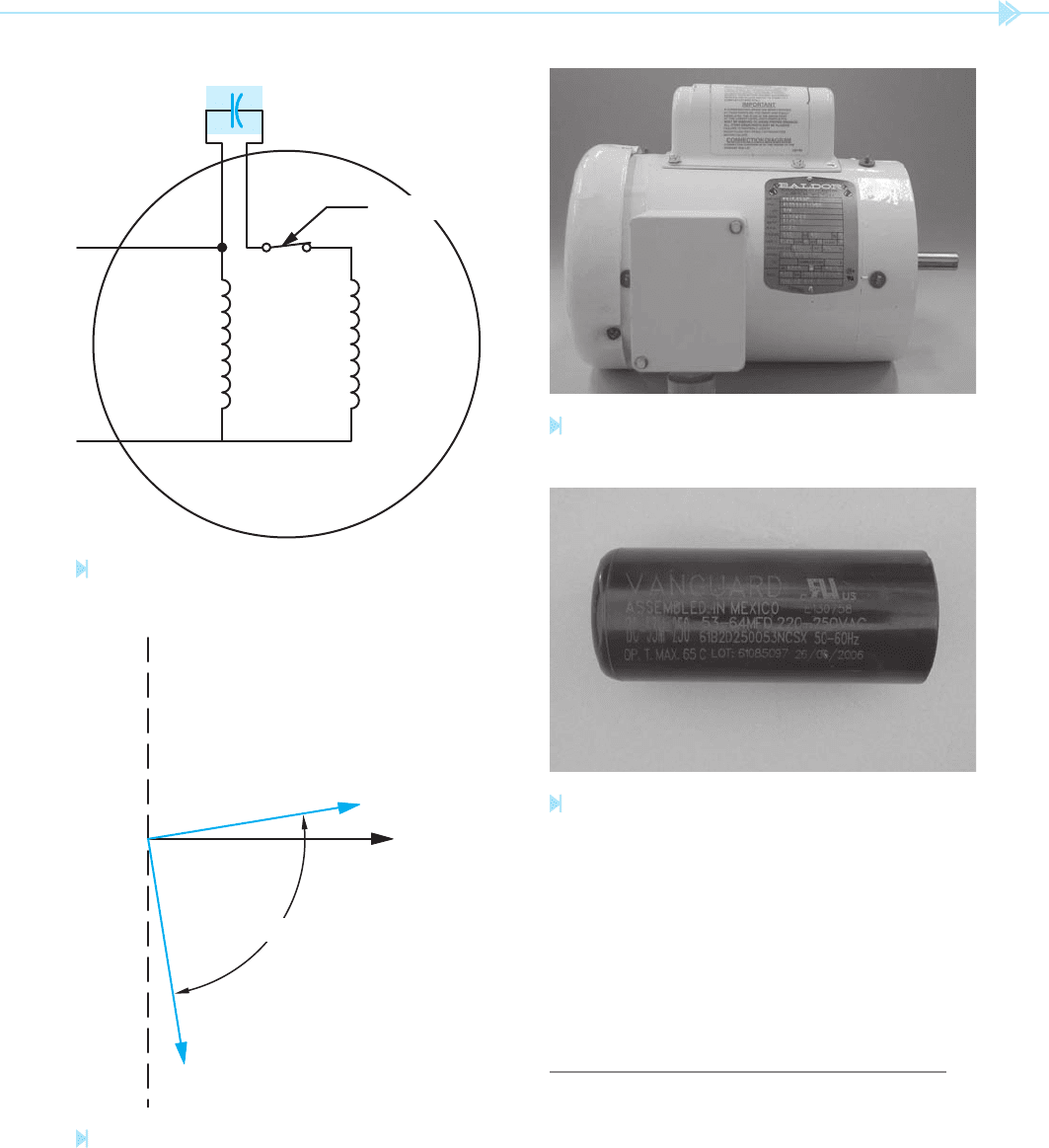
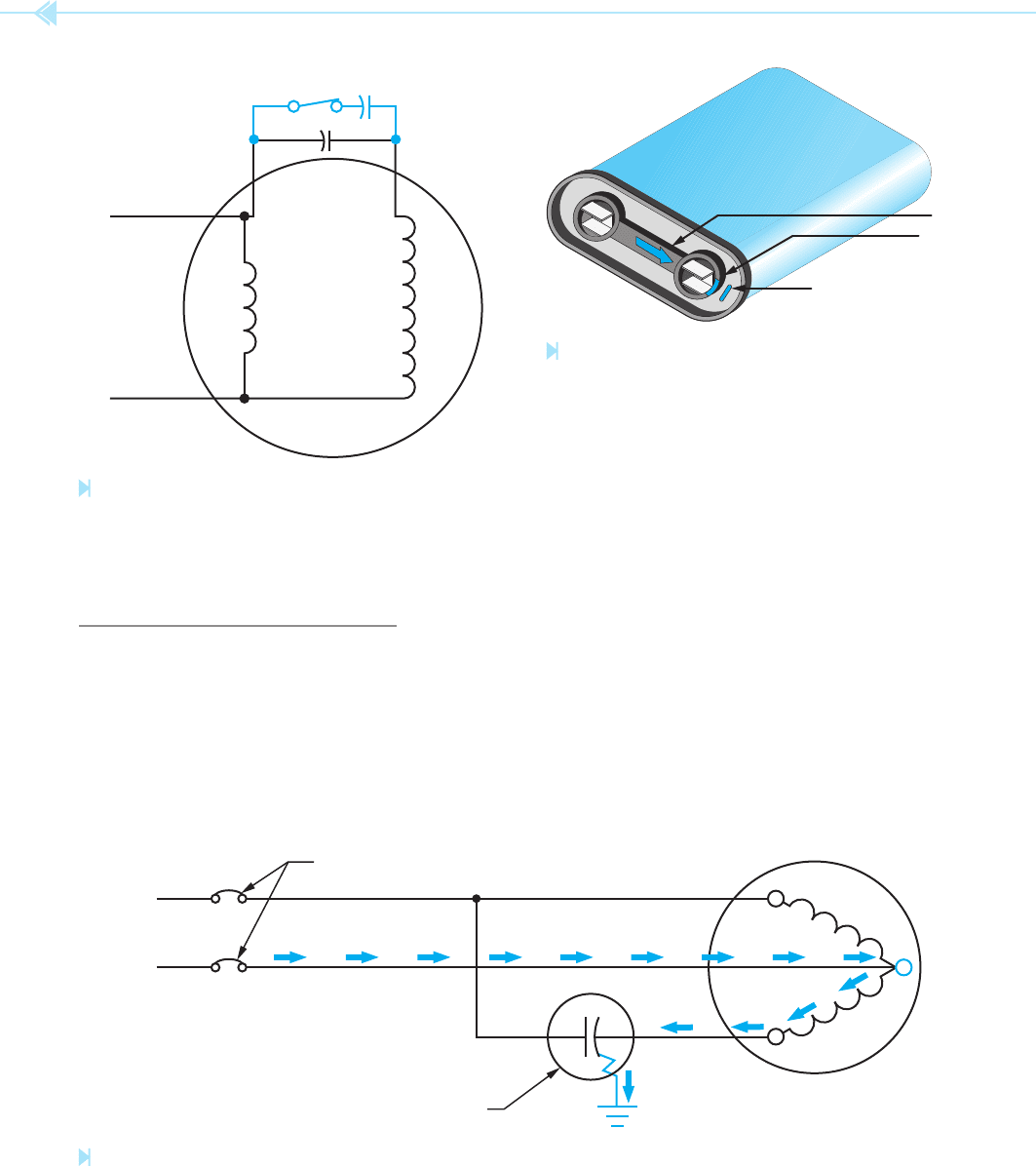
The main difference is that a capacitor is con-
nected in series with the start winding, as shown in
Figure 11–11. Inductive loads cause the current to
lag the applied voltage. Capacitors, however, cause
the current to lead the applied voltage. If the start-
ing capacitor is sized correctly, the start winding
current will lead the applied voltage by an amount
that will result in a 90-degree phase shift between
the run winding current and the start winding
current, producing an increase in the amount of
starting torque, as shown in Figure 11–12. If the
capacitance of the start capacitor is too great, it
will cause the start winding current to shift more
than 90 degrees out-of-phase with the run wind-
ing current and starting torque will be reduced.
When replacing the start capacitor for this type
UNIT 11 Split-Phase Motors 123
of motor, the micro-farad rating recommended by
the manufacturer should be followed. It is permis-
sible to use a capacitor with a higher voltage rating,
but never install a capacitor with a lower voltage
rating. A capacitor-start induction-run motor is
shown in Figure 11–13. A typical starting capacitor
is shown in Figure 11–14.
TESTING THE STATOR WINDING
The stator winding of a single-phase motor is gen-
erally tested with an ohmmeter. The ohmmeter
test can be used to determine if a winding is open
or grounded. Many single-phase motors have one
Run
Winding
Start
Winding
Start
Capacitor
Centrifugal Switch
Figure 11–11
A capacitor is connected in series with the start
winding. (Source: Delmar/Cengage Learning)
Figure 11–12
The capacitor causes a 90-degree phase shift between
run winding current and start winding current.
(Source: Delmar/Cengage Learning)
Figure 11–13
A capacitor-start induction-run motor. (Source: Delmar/
Cengage Learning)
Figure 11–14
Typical starting capacitor. (Source: Delmar/Cengage Learning)
Start Winding
Current
Voltage
Run Winding
Current
90°
124 SECTION 3 Motors
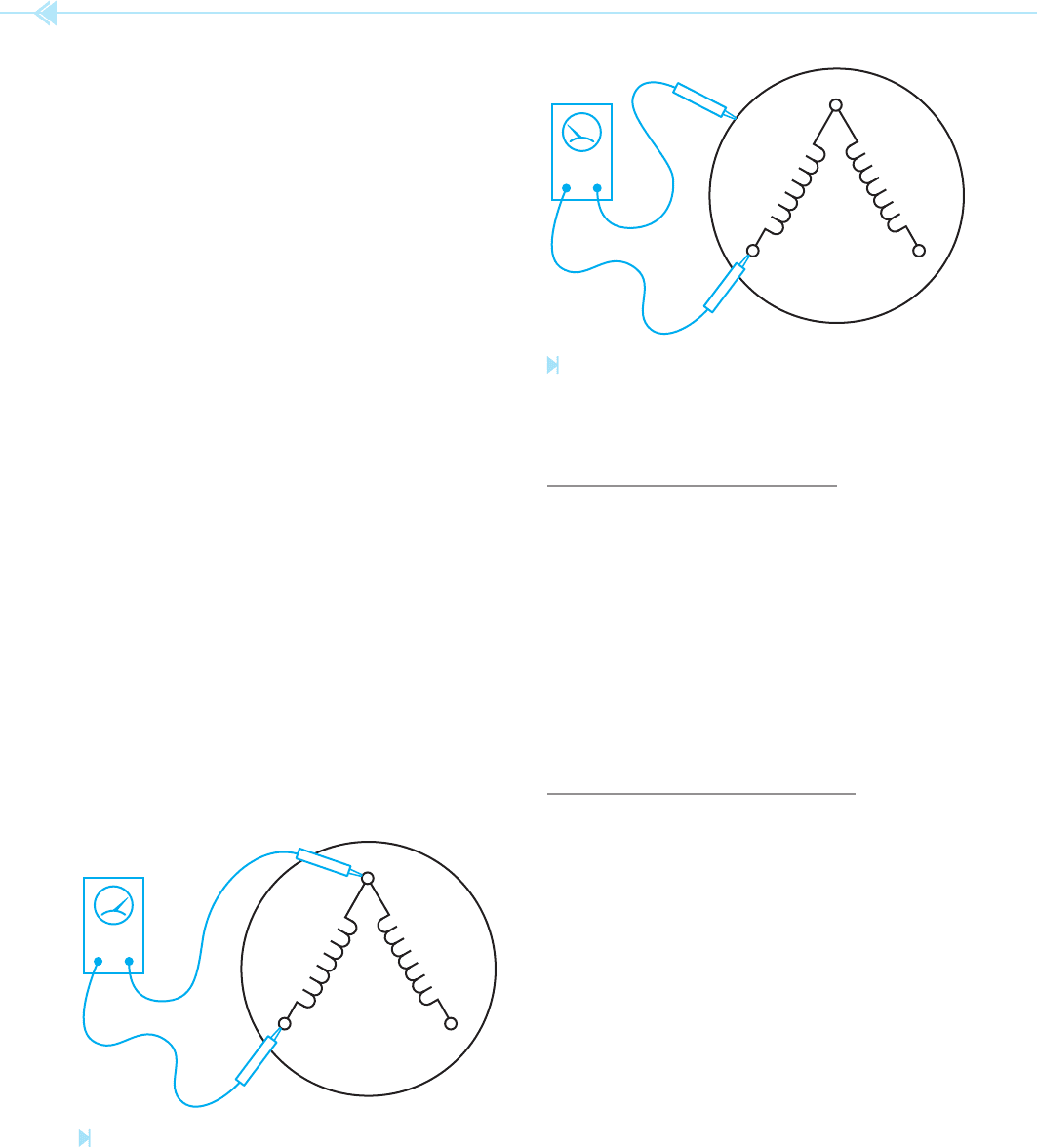
lead of the run and start windings connected as
shown in Figure 11–15. To test the windings for
an open, connect one ohmmeter lead to the com-
mon motor terminal, and the other meter lead to
the run winding. The ohmmeter should indicate
continuity through the winding. The resistance of
the run winding of a single-phase motor can vary
greatly from one motor to another. The winding
resistance of a single-speed motor may be only one
or two ohms, while the resistance of a multi-speed
fan motor may be 10 to 15 ohms.
To test the start winding for an open, connect the
ohmmeter leads to the common terminal and the
S terminal. The start winding should indicate conti-
nuity, and should have a higher resistance than the
run winding. This difference of resistance may not
be great, but the start winding should have a higher
resistance than the run winding.
To test the stator winding for a ground, connect
one of the ohmmeter leads to the case of the motor,
Figure 11–16. Alternately check each motor termi-
nal with the other ohmmeter lead. The ohmmeter
should indicate no continuity between either wind-
ing and the case of the motor.
A shorted start winding can sometimes be
detected by the fact that the motor will not start, but
will run if the shaft is turned by hand. The motor
will produce a humming sound but will not turn
when power is rst applied to it. The shaft can be
turned in either direction by hand and the motor
will continue to run in that direction.
C
SR
C
SR
Figure 11–15
Testing the split-phase motor for an open winding.
(Source: Delmar/Cengage Learning)
Figure 11–16
Testing a split-phase motor for a grounded winding.
(Source: Delmar/Cengage Learning)
REVERSING DIRECTION
OF ROTATION
The direction of rotation of a split-phase motor can
be reversed by changing the start winding leads or
the run winding leads, but not both. The rotation is
generally reversed by changing the start winding
leads with respect to the run winding. Some motor
manufacturers bring both start winding leads to the
outside of the motor. This permits the service techni-
cian to decide the direction of rotation the motor is
to turn when it is installed on the unit.
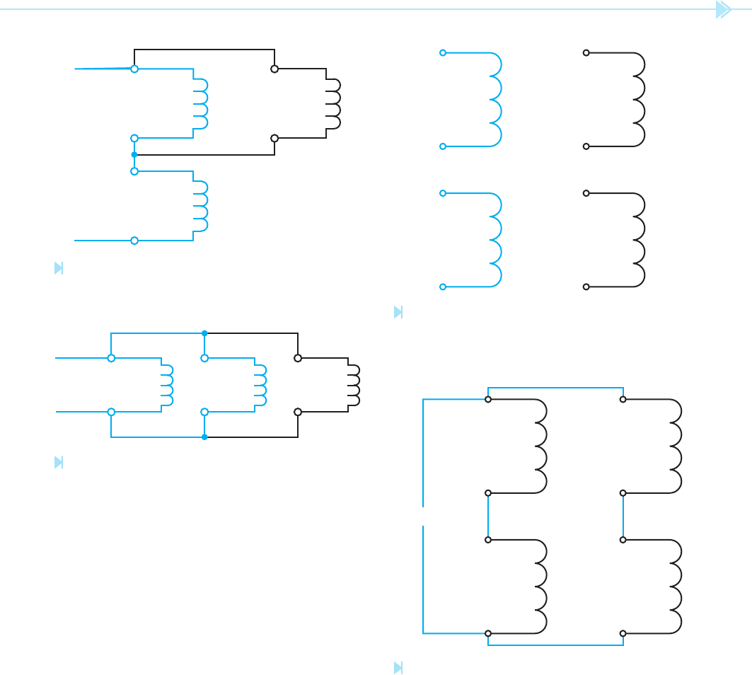
DUAL-VOLTAGE MOTORS
Single-phase motors can also be constructed to
operate on two separate voltages. These motors
are designed to be connected to 120 or 240 volts.
A common connection for this type of motor con-
tains two run windings and one start winding,
Figure 11–17. The run windings are labeled T1–T2,
and T3–T4. The start winding is labeled T5 and T6.
In the circuit shown in Figure 11–17, the windings
have been connected for operation on a 240-volt
line. Each winding is rated at 120 volts. The two
run windings are connected in series, which causes
each to have a voltage drop of 120 volts when con-
nected to 240 volts. Notice that the start winding
has been connected in parallel with one of the run
windings. This causes the start winding to have an
UNIT 11 Split-Phase Motors 125
applied voltage of 120 volts also. Notice that each of
the windings has 120 volts connected to it, which is
the rating of the windings.
If the motor is to be operated on a 120 volt line,
the windings are connected in parallel as shown
in Figure 11–18. Because these windings are con-
nected in parallel, each will have 120 volts applied
to it.
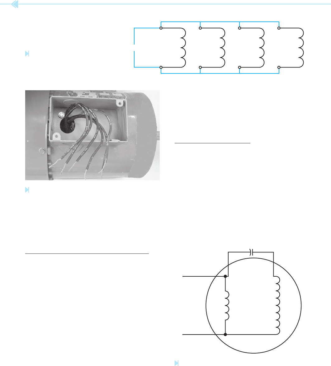
Some dual-voltage motors will contain two start
windings as well as two run windings, as shown
in Figure 11–19. The run windings are labeled T
1
through T
4
, the same as dual-voltage motors that
contain only one start winding. One of the start
windings is labeled T
5
and T
6
. The second start
winding is labeled T
7
and T
8
. If the motor is to be
connected for operation on 240 volts, the run wind-
ings are connected in series by connecting T
2
and
T
3
together, and the start windings are connected
in series by connecting T
6
and T
7
together. The
Figure 11–17
The run windings are connected in series for a high-
voltage connection. (Source: Delmar/Cengage Learning)
T
5
T
6
S
T
A
R
T
T
1
T
2
R
U
N
T
3
T
4
L
2
L
1
R
U
N
Figure 11–18
Because these windings are connected in parallel, each
will have 120 volts applied to it. (Source: Delmar/Cengage Learning)
START
T
5
T
6
RUN
T
3
T
4
RUN
N
H
T
1
T
2
Figure 11–19
Some dual-voltage single-phase motors contain two
start windings as well as two run windings. (Source: Delmar/
Cengage Learning)
T1
T2
S
T
A
R
T
R
U
N
T
5
T6
T3
T4
S
T
A
R
T
R
U
N
T
7
T8
Figure 11–20
The motor is connected for operation on 240 volts.
(Source: Delmar/Cengage Learning)
T1
T2
S
T
A
R
T
R
U
N
T
5
T6
T3
T4
S
T
A
R
T
R
U
N
T
7
T8
240 Volts
start windings are then connected in parallel with
the run windings, as shown in Figure 11–20. The
direction of rotation can be changed by reversing
T
5
and T
8
.
If the motor is operated on 120 volts, the run and
start windings are connected in parallel as shown in
Figure 11–21. If the motor is to be reversed, leads
T
5
and T
7
are changed with leads T
6
and T
8
. Some
126 SECTION 3 Motors
T1
R
U
N
R
U
N
S
T
A
R
T
S
T
A
R
T
T
2
T3
T4
T5
T6
T7
T8
120 Volts
Figure 11–22
Connection leads of a dual-voltage single-phase motor.
(Source: Delmar/Cengage Learning)
Figure 11–23
A schematic for a permanent-split capacitor motor.
(Source: Delmar/Cengage Learning)
Figure 11–21
The motor is connected for
operation on 120 volts. (Source: Delmar/
Cengage Learning)
manufacturers label the start winding leads T
5
and
T
8
even if they contain only one start winding. The
connection leads of a dual-voltage single-phase
motor are shown in Figure 11–22.
MOTOR POWER CONSUMPTION
It should be noted that the motor does not use less
energy when connected to 240 volts than it does
when connected to 120 volts. Power is measured
in watts, and the watts will be the same regardless
of the connection. When the motor is connected to
operate on 240 volts, it will have half the current
draw as it does on a 120-volt connection. Therefore,
the amount of power used is the same. For example,
assume the motor has a current draw of 5 amps when
connected to 240 volts and 10 amps when connected
to 120 volts. Watts can be computed from multiply-
ing volts by amps. When the motor is connected
to 240 volts, the amount of power used is 240 ⫻
5 = 1,200 watts. When the motor is connected to
120 volts, the power used is 120 ⫻ 10 = 1,200 watts.
The 240-volt connection is generally preferred, how-
ever, because the lower current draw causes less volt-
age drop on the line supplying power to the motor. If
the motor is located a long distance from the panel,
voltage drop of the wire can become very important
to the operation of the unit.
PERMANENT-SPLIT
CAPACITOR MOTOR
The permanent-split capacitor motor has greatly
increased in popularity for use in the air condition-
ing eld over the past years. This type of split-phase
motor does not disconnect the start windings from
the circuit when it is running. This eliminates
the need for a centrifugal switch or starting relay
to disconnect the start windings from the circuit
when the motor reaches about 75% of its full speed,
Figure 11–23. This motor has good
starting torque
STARTRUN
RUN
CAPACITOR
H
N
UNIT 11 Split-Phase Motors 127
Figure 11–25
Permanent-split capacitor motor. (Source: Delmar/Cengage Learning)
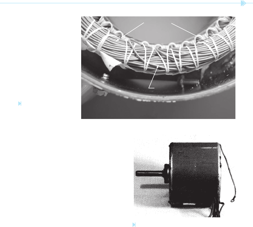
Figure 11–24
The run and start windings
of a permanent-split capacitor
motor. (Source: Delmar/Cengage Learning)
Start Windings
Run Winding
and good running torque. Because the capacitor
remains in the circuit during operation, it helps
correct power factor for the motor. The stator
winding of the permanent-split capacitor (PSC)
motor is different from the stator windings of the
resistance-start induction-run or capacitor-start
induction-run motors. The PSC motor stator wind-
ing still contains a run and start winding, but the
start winding will generally have the same size
wire and just as many turns as the run winding, as
shown in Figure 11–24. The run winding is placed
lower in the core material, which helps increase the
inductance.
The capacitor used in this type of motor is
generally the AC oil- lled type. A photograph of
a permanent-split capacitor motor is shown in
Figure 11–25. Because this capacitor remains con-
nected in the circuit, an AC electrolytic capacitor
cannot be used to replace the run capacitor for this
type of motor.
The permanent-split capacitor motor will some-
times use an extra capacitor to aid in starting.
When this is done, the start capacitor is connected
in parallel with the run capacitor. During the time
of starting, both of these capacitors are connected
in the circuit, Figure 11–26. When the motor has
accelerated to about 75% of full speed, the start
capacitor is disconnected from the circuit. If the
motor is an open type, the start capacitor will be
disconnected by a centrifugal switch. If the motor
is sealed, such as a hermetically sealed compressor,
the start capacitor will be disconnected by a starting
relay.
128 SECTION 3 Motors
START
CAPACITOR
STARTRUN
RUN
CAPACITOR
H
N
Arrow
Dot
Dash
RUN CAPACITOR
CIRCUIT BREAKER
240 VOLTS
C
S
R
RUN
START
Figure 11–26
An extra starting capacitor used with a permanent-split
capacitor motor. (Source: Delmar/Cengage Learning)
Figure 11–28
Identifi ed capacitor terminal connected to motor start winding. (Source: Delmar/Cengage Learning)
Figure 11–27
The markings indicate the terminal that connects to the
plate located closest to the case of the capacitor.
(Source: Delmar/Cengage Learning)
IDENTIFYING CAPACITOR
TERMINALS
Most run capacitors and some starting capacitors
are of the oil- lled type, Figure 8–15. This is espe-
cially true for high current motors such as those
used to operate compressors. Many manufacturers
of oil- lled capacitors will identify one terminal with
an arrow, a painted dot, or by stamping a dash in
the capacitor can, Figure 11–27. This identi ed
terminal marks the connection to the plate that is
located nearer to the metal container or can. It has
long been known that when a capacitor’s dielectric
breaks down and permits a short circuit to ground,
it is most often the plate nearer to the outside case
that becomes grounded. For this reason, it is desir-
able to connect the identi ed capacitor terminal to
the line side instead of to the motor start winding.
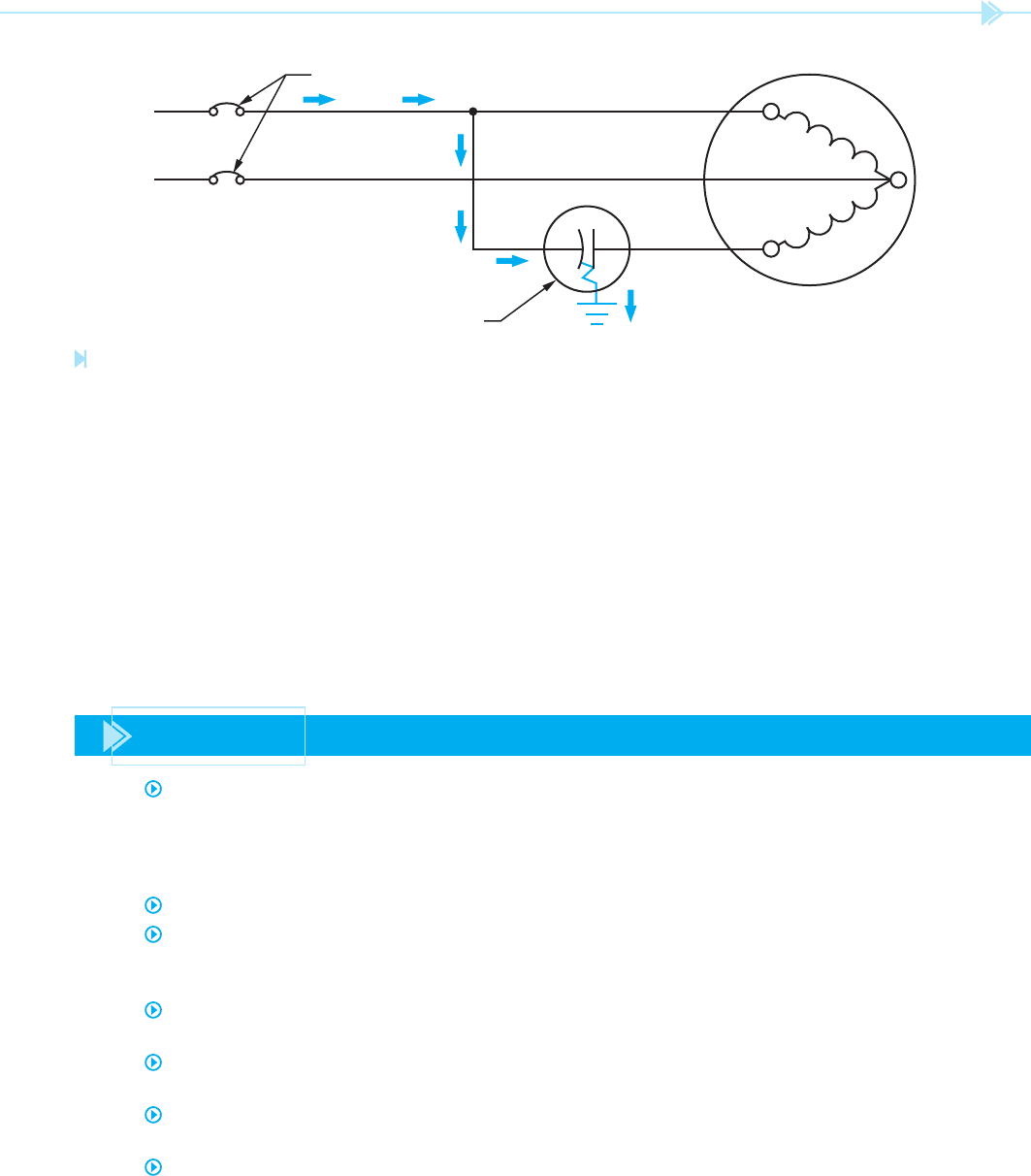
In Figure 11–28, the run capacitor has been con-
nected in such a manner that the identi ed terminal
is connected to the start winding of a compressor
UNIT 11 Split-Phase Motors 129
RUN CAPACITOR
CIRCUIT BREAKER
240 VOLTS
C
S
R
RUN
START
Figure 11–29
Identifi ed capacitor terminal connected to the line. (Source: Delmar/Cengage Learning)
motor. If the capacitor shorts to ground, a current
path would exist through the motor start winding.
The start winding is an inductive-type load and
inductive reactance will limit the value of current
ow to ground. Since the ow of current is limited,
it will take the circuit breaker or fuse time to open
the circuit and disconnect the motor from the power
line. This time delay can permit the start winding to
overheat and become damaged.
In Figure 11–29, the run capacitor has been
connected in such a manner that the identi ed
terminal is connected to the line side. If the capaci-
tor shorts to ground, a current path would exist
directly to ground, bypassing the motor start wind-
ing. When the capacitor is connected in this man-
ner, the start winding does not limit current ow
and allows the fuse or circuit breaker to open
almost immediately.
SUMMARY
Split-phase motors fall into three general classi cations:
A. The resistance-start induction run.
B. The capacitor-start induction run.
C. The permanent-split capacitor motor.
The voltages of a two-phase system are 90° out of phase with each other.
Split-phase motors receive their name from the fact that they split the current ow
through two windings to produce an out of phase condition that produces a rotating mag-
netic eld.
The resistance-start induction run and capacitor-start induction run motors disconnect
their start winding when they have accelerated to about 75% of their rated speed.
Split-phase motors that are not hermetically sealed generally use a centrifugal switch to
disconnect the start winding when the motor has reached about 75% of its rated speed.
The direction of rotation of a split-phase motor can be reversed by changing the connec-
tions of the run winding or the start winding, but not both.
Dual voltage split-phase motors can be connected to operate on 120 or 240 volts.