Stacey F.D., Davis P.M. Physics of the Earth
Подождите немного. Документ загружается.

//FS2/CUP/3-PAGINATION/SDE/2-PROOFS/3B2/9780521873628C14.3D
–
197
– [197–223] 13.3.2008 12:37PM
14
Kinematics of the earthquake process
14.1 Preamble
Elucidation of the details of the tectonic pattern
is one of the incentives for seismicity studies.
Another is earthquake prediction. In the 1960s
and early 1970s there was a widespread, but
not universal, expectation that a decade or so
of intensive research would yield a methodology
for predicting the times, places and magnitudes
of earthquakes. The task was underestimated
because the physical mechanism of earthquakes
is not as simple as was supposed. In spite of the
lack of success we now have a somewhat clearer
perception of the earthquake process, although
rather little encouragement to believe that
detailed prediction is possible. Nevertheless,
research with this aim continues, so we can
expect further improvement in our understand-
ing of earthquake mechanisms.
The underlying driving power for earth-
quakes is derived from thermal convection of
the mantle, the subject of a thermodynamic
analysis in Chapter 22. We can compare the
energy released by earthquakes with the energy
that is shown thermodynamically to be avail-
able. Except for a few shallow shocks, for
which fault displacements are directly observed,
earthquake energies are estimated from the radi-
ated elastic waves. Energy is directly related to
magnitude and, given the numbers of earth-
quakes as a function of magnitude, we can inte-
grate over all earthquakes to estimate the total
energy release. Typically, the efficiency for con-
version of static elastic energy to seismic waves
is estimated as 6%. Although there is substantial
uncertainty in this number, it suffices for an
order of magnitude estimate of the fraction of
total convective energy that is released as earth-
quakes, 3%. Most of the mantle deformation
occurs aseismically. Implications for rheology
and the pattern of mantle convection are consid-
ered in Sections 12.5 and 13.2.
Most earthquakes occur at depths too great to
allow access to the source zones with boreholes
or tunnelling. The earthquake process is gener-
ally inferred from radiated seismic waves, but
direct observation of surface displacements in
some shallow shocks give convincing confirma-
tion of the mechanism. To a first approximation
an earthquake is a dislocation (Fig. 10.5), with
displacement of the rock on opposite sides of a
fault that grows from a starting point, termed
the hypocentre. The spectrum of radiated waves
is characteristic of fault dimensions and can be
used to estimate them. The lowest frequencies,
(longest wavelengths) are used to estimate earth-
quake strength or moment. Seismic moment is
the product of slip, area of a fault and elastic
modulus. Detailed seismic analysis of waves
from very large earthquakes, such as the 2004
Sumatra–Andaman event, reveals that, at any
instant, movement is restricted to a limited
area of the fault, a slipping patch, that travels
from one end of the fault to the other, breaking
material in front of it and leaving behind broken
material that eventually ‘heals’. Waves ‘pile up’
in the forward direction and are spread out in
the backward direction. This directivity, appa-
rent as an asymmetry in the radiation pattern,

//FS2/CUP/3-PAGINATION/SDE/2-PROOFS/3B2/9780521873628C14.3D
–
198
– [197–223] 13.3.2008 12:37PM
is a Doppler effect, and is used to determine the
direction and speed of fault propagation. Modern
seismic arrays reveal fine details, indicating that
large dislocations can be regarded as superposi-
tions of many sub-events.
Plate tectonic reconstructions and space
geodesy have been used to calculate slip across
tectonic boundaries. Comparison with the slip
evident in earthquakes allows an estimate of
the fraction of the plate motion in a given
tectonic region that is accounted for by earth-
quakes and not by aseismic creep. Because very
large earthquakes are rare, summing moments
from historic earthquakes is inadequate. Most of
the slip takes place in the largest events.
Section 14.7 describes a method of estimating
the effects of the rare large events by a statistical
analysis of the smaller events.
Large thrust and normal earthquakes in the
sea floor cause vertical motions that generate
tsunamis. Only earthquakes with fault dimen-
sions hundreds of kilometres in extent are effec-
tive. They cause tsunamis, with wavelengths
comparable to the fault dimensions, that propa-
gate in oceans, 5 km deep, as shallow water
waves, meaning that they have wavelengths
much greater than the water depth. The waves
travel across the ocean at a speed more than an
order of magnitude faster than normal wind
driven waves but less than the speeds of seismic
waves by a similar factor. Seismic signals are
used as a basis of tsunami warning systems, sup-
plemented by sea floor pressure observations.
14.2 Earthquakes as dislocations
Earthquakes result from rapid fault slip but only
rarely do the faults break the surface. Shallow
transcurrent (strike-slip) faults, across which
horizontal displacements occur at the surface,
provide an exception. The San Andreas fault
in California is a notable example. Thus, the
seismicity of California has played a vital role
in recognizing earthquakes as fault movements.
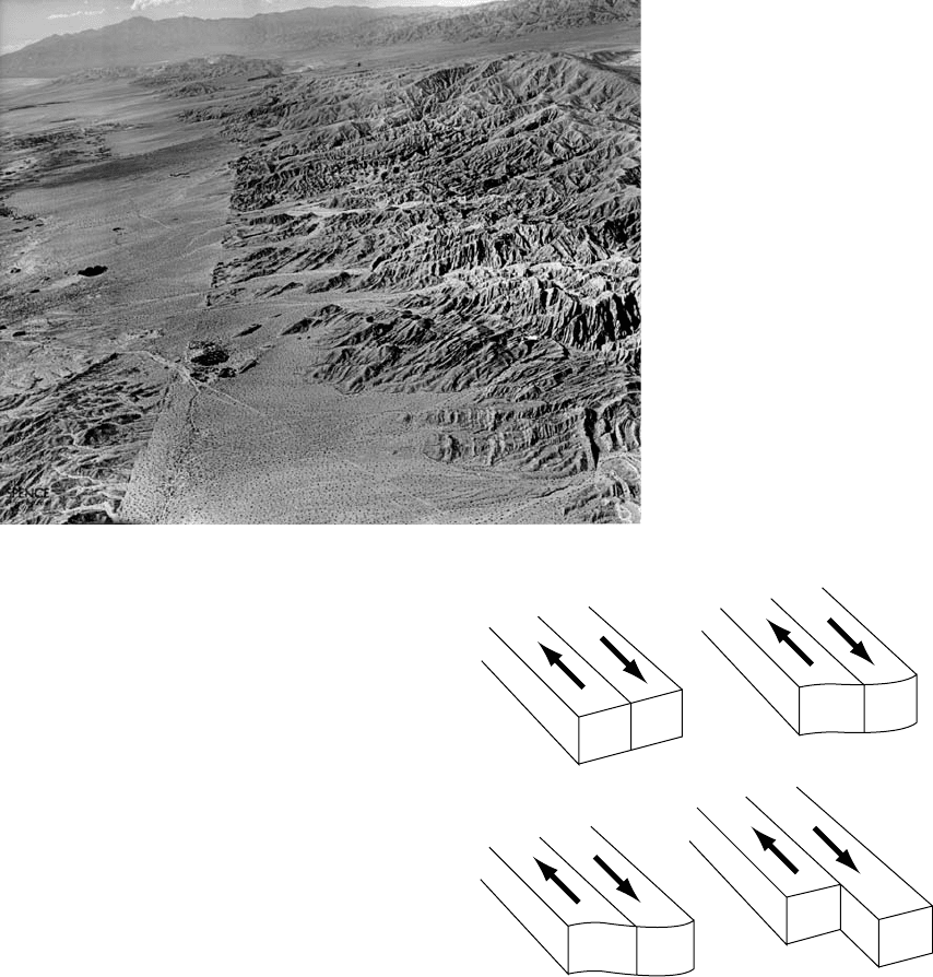
An example is shown in Fig. 14.1. The fact that
repeated movements occur in the same direc-
tion, and accumulate as large fault offsets, is
illustrated in Fig. 14.2, making it obvious that
earthquakes are local increments in the pattern
of tectonic motion.
Impressive as horizontal movements on trans-
current faults often are, it is important to recog-
nize that they have a secondary role in the
tectonic scheme. The energy is ultimately deri-
ved from convection, for which the essential,
primary mass movements are vertical. The
world’s major thrust faults (see Fig. 14.10(b)),
FIGURE 14.1 Fault
displacement that occurred
though an orange grove during
an earthquake in Imperial Valley,
California, in September, 1950.
Photograph by David Scherman,
Life Magazine # Time Inc.
198 KINEMATICS OF THE EARTHQUAKE PROCESS
//FS2/CUP/3-PAGINATION/SDE/2-PROOFS/3B2/9780521873628C14.3D
–
199
– [197–223] 13.3.2008 12:37PM
across which vertical slip occurs, are responsible
for most of the moderate and large earthquakes,
but they are generally deeper and are not directly
observed. Decades of observations of fault move-
ments so strongly emphasized horizontal dis-
placements that they probably delayed by many
years recognition of the underlying tectonic
mechanism.
The San Francisco earthquake of 1906 has a
special place in the history of seismicity studies.
A geodetic survey of the area had been com-
pleted shortly before the earthquake and was
repeated after it, providing detailed, quantitative
documentation of the displacements. Reid (1910)
used the data to support what he called the elas-
tic rebound theory of earthquakes. The theory
was not entirely new, but Reid’s evidence made
it convincing and it became central to ideas
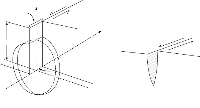
about the earthquake mechanism. The elastic
rebound theory is represented diagrammatically
in Fig. 14.3. It envisages a progressive regional
movement, causing elastic deformation of the
ground until a breaking point is reached, when
displacement across a fault releases the elastic
strain. The concept of a progressive regional
movement causing build-up of elastic strain,
which is abruptly released in occasional events,
falls naturally into place with current ideas
about plate tectonics. Thus the essential validity
of the elastic rebound theory is not subject to
doubt. However, the concept of a breaking point
is simplistic. We still have no clear idea of what
FIGURE 14.2 Mismatch of
geological features across a
branch of the San Andreas fault
near Indio, California. Photograph
by Spence Air Photos.
(a)
(b)
(c) (d)
FIGURE 14.3 The elastic rebound theory of an
earthquake, as advanced by Reid (1910) to explain the
San Francisco 1906 event. Regional shearing movement
gradually builds up elastic strain from state (a) to state
(c), at which it is suddenly released across the fault,
producing the displacement in (d).
14.2 EARTHQUAKES AS DISLOCATIONS 199
//FS2/CUP/3-PAGINATION/SDE/2-PROOFS/3B2/9780521873628C14.3D
–
200
– [197–223] 13.3.2008 12:37PM
triggers earthquakes or what limits the spread
of a fault break once it starts. This is a difficulty
that limits progress in earthquake prediction.
Fault displacements, and the associated elas-
tic strains and stresses, are described by equa-
tions that are collectively termed dislocation
theory. Some of the jargon is adopted directly
from solid-state physics in which there is an
extensive literature on dislocations. They occur
as defects in crystals and control their strengths
and mechanisms of deformation. There are two
basic kinds, illustrated in Fig. 10.5. Consider a
solid body of convenient shape, make a half-cut
in it and displace the material on opposite faces
of the cut. The axis of the dislocation is the edge
of the cut and the relative displacement of the
faces is the displacement or Burgers vector. If this
is parallel to the axis, as in Fig. 10.5(a), then the
result is a screw dislocation. If the displacement
vector is perpendicular to the axis (Fig. 10.5(b)),
it produces an edge dislocation, and in general
we have mixed dislocations, with both types of
displacement.
To a useful approximation, the San Francisco
1906 earthquake can be modelled as a screw dis-
location. Another intensively studied earthquake,
Alaska 1964, resembles a pair of edge disloca-
tions. These simple models represent faults that
are much longer in one dimension than the other.
The simple dislocations envisaged in Fig. 10.5 are
described by two-dimensional equations, that is,
they assume uniformity along the axis or an effec-
tively infinite length. More general equations
are needed for faults that are nearer to equi-
dimensional (see Section 14.3). Another generali-
zation that is needed for realistic application to
earthquakes is a grading of slip to zero at fault
boundaries. For faults that break the surface it is
the gradient of the slip that must be zero at the
surface.
Ground displacements accompanying the San
Francisco 1906 earthquake extended for hund-
reds of kilometres along the San Andreas fault,
but were concentrated in a band about 15 km
either side of it. This means that the break was
shallow and quite well represented by a screw
dislocation, although the slip was variable along
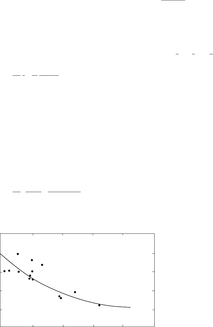
the length of the fault. Figure 14.4(a) gives the
geometry for a simple screw dislocation that
models this situation, with its axis parallel to the
surface at depth D. Initially we calculate the strain
for a dislocation in an infinite medium and then
take account of the free surface by introducing
a hypothetical image dislocation above the sur-
face. For the infinite medium the circle of radius r
about the dislocation axis, which is shown as a
(b)
Fault
displacement
S
x
z
y
D
S
2
S
2
(a)
Surface
fault
Dislocation axis
FIGURE 14.4 (a) Geometry of a screw dislocation, the mathematical model of a transcurrent fault. Displacement, S,
is uniform to depth D and zero below that, twisting the circle (broken line) into a helical form. (b) A more realistic
variation of displacement with depth.
200 KINEMATICS OF THE EARTHQUAKE PROCESS
//FS2/CUP/3-PAGINATION/SDE/2-PROOFS/3B2/9780521873628C14.3D
–
201
– [197–223] 13.3.2008 12:37PM
broken line for the unfaulted medium, is defor-
med to the helical curve (solid line). The shear
strain, ", is uniform around the circumference
of this circle and is therefore given by
" ¼ b=2pr; (14:1)
where b is the displacement (Burger’s vector). We
are primarily interested in the component "
yz
of
this strain across a vertical plane, y ¼constant,
parallel to the fault plane (y ¼0),
"
yz
¼
b
2pr
x
r
¼
b
2p
x
ðx
2
þ y
2Þ
: (14:2)
This gives the strain component in an infinite
medium, due to a single dislocation of displace-
ment, S ¼b.
We may now consider the effect of a free sur-
face at x ¼D. Since there are no stresses across
the surface, the shear strain across it, "
xz
, is zero
everywhere on the plane. Mathematically, this
situation can be achieved by introducing to the
infinite medium a hypothetical mirror image
dislocation at x ¼2D. The effect of the two dis-
locations together would be to give slip S for
0 < x < 2D but zero outside this range. The second
dislocation does not cancel "
yz
, which becomes
"
yz
¼
b
2pr
x
x
2
þ y
2
þ
2D x
ð2D xÞ
2
þ y
2
!
: (14:3)
In the free surface (x ¼D), where observations are
normally made,
"
D
¼ "
yz
ðDÞ¼
bD
pðD
2
þ y
2
Þ
: (14:4)
Thus displacements of surface points at arbi-
trary distance, y, from the fault are obtained by
integrating the strain, "
D
, with respect to y, not-
ing the discontinuity in displacement at y ¼0,
displacement ¼
ð
y
1
"
D
dy ¼
b
2
1
2
p
tan
1
y
D
: (14:5)
Equation (14.5) gives the surface displace-
ment (in the z direction) due to a simple disloca-
tion with a discontinuity of fault displacement
on the dislocation axis at depth D (x ¼0). There
are singularities in stress and strain on the
axis and the model can be improved by grad-
ing the fault slip to zero as x !0(butkeeping
the variation of slip with depth zero as x !D)
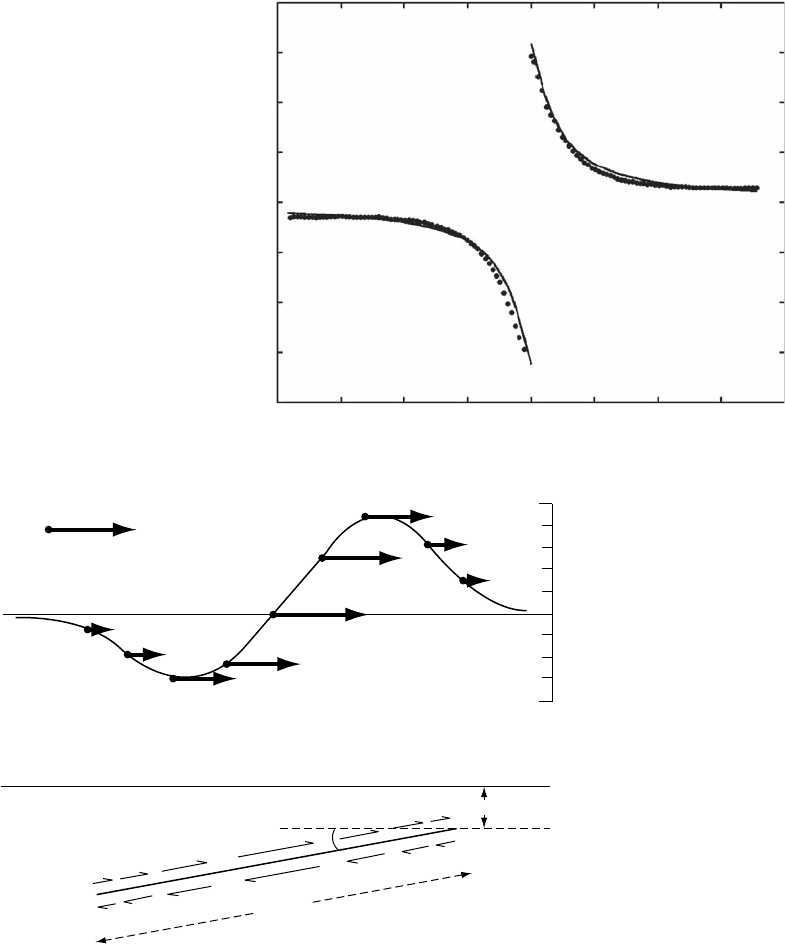
as in Fig. 14. 4(b). The effect of these refine-
ments is too slight to affect the f it of the
geodetic observa tions (Fig. 14.5) made after
the 190 6 earthquake, and the curve shown is
for a simple dislocatio n. Other unmodelled
effects include variabili ty of displac ement
along the fault and heterogeneity of the
medium. Recent ly mu ch finer o bserv ations
using radar interferometry from satellite s
have provided detailed displacement maps
that allow heterogeneity to be identified
(Peltzer et al., 1999). A cross-section of ground
displacements resu lting from the 1996 Manyi
2
1
0
0
2
46
810
Displacement (metres)
Distance from fault (kilometres) NE
FIGURE 14.5 Horizontal
displacement of surface points on
the NE side of the San Andreas
fault that occurred during the San
Francisco 1906 earthquake. The
curve represents Eq. (14.5) with
S ¼4 m and D ¼3.4 km. To allow
for grading of slip, as in Fig.
14.4(b) a somewhat greater total
fault depth must be favoured.
14.2 EARTHQUAKES AS DISLOCATIONS 201
//FS2/CUP/3-PAGINATION/SDE/2-PROOFS/3B2/9780521873628C14.3D
–
202
– [197–223] 13.3.2008 12:37PM
strike-slip earthquake in Tibet (Fig. 14.6 ) show
a r emarkable fit to predictions of Eq. (14.5 ),
but asymmetry of other cross-sections led
Peltzer et al. to conclude that elast ic response
about the fault was variable.
A model of the Alaska 1964 earthquake is
shown as the lower part of Fig. 14.7, with corre-
sponding surface displacements, in the top half
of the figure, matched to the available observa-
tions. The Alaska 1964 earthquake cannot be
–400
–300
–200
–100
0
100
200
300
400
–80 –60 –40 –20 0 20 40 60
80
Displacement (cm)
Distance perpendicular to fault (km)
Manyi (Tibet) Mw 7.6 earthquake
FIGURE 14.6 Displacements
determined from InSar
(interferometric synthetic
aperture radar) for the 1996
Manyi, Tibet, earthquake, from
data by Peltzer et al. (1999). A fit to
Eq. (14.5), with S ¼6.84 m, and
D ¼7.9 km, of data provided by
Gilles Peltzer.
9
30
km
SE
NW
5
–4
0
Vertical displacement (m)
Horizontal
displacement vectors
Sea level
(20
m)
250
km
–22
m
+22
m
FIGURE 14.7 A model of fault movement during the Alaska 1964 earthquake, matched to observed displacements
of the surface reported by Plafker (1965). The model assumes that the fault did not break the surface, but if it did so
the break would have been at sea.
202 KINEMATICS OF THE EARTHQUAKE PROCESS
//FS2/CUP/3-PAGINATION/SDE/2-PROOFS/3B2/9780521873628C14.3D
–
203
– [197–223] 13.3.2008 12:37PM
modelled as simply as the San Francisco 1906
earthquake. It is represented by a pair of com-
pound edge dislocations with graded displace-
ments. This is a two-dimensional model. The
fault length, roughly parallel to the Alaska
coast, was about 800 km, four times the width
and sufficient to make the two-dimensional
model satisfactory over the central section of
the fault. Equations for edge dislocations, not
presented here, are not as simple as those for
screw dislocations, partly because the free sur-
face cannot be accounted for by a single, simple
image. Equations for displacements due to arbi-
trarily oriented faults are given by Mansinha and
Smylie (1971) and Okada (1985).
We can estimate the maximum strains, close
to the faults, for the two earthquakes consid-
ered and use the elasticity of the Earth at app-
ropriate depths to obtain the corresponding
stresses. For San Francisco we may take the
movement on each side of the fault to be 2 m
and distribute this displacement over the depth
of the fault. The simple dislocatio n model gives
the depth as about 3.5 km, b ut a deta iled analy-
sis, using a more realistic c ompound dislocation
model, gives (5.0 1.5) km. It is puzzling that
the movement on a fault break hundreds of
kilometres in length should be so shallow, but
using the latter figure, the strain is 4 10
4
and
taking the crustal rigidity as 30 GPa the drop in
shear stress across the fault was 1 2 MPa (120
bar). This is an u pper bound, as slip was variable
along the fault and a high value is assumed.
On other fault sections the stress drop may not
have exceeded 2 MPa. For the Alaska 1964 shock
we distribute the 22 m maximum displacement
over the half-width of the fault, 125 km, to
obtain a strain of 1.8 10
4
. At t he greater
average depth of this shock the shear modulus
is about 55 GPa, giving a stress drop of 9.9 MPa
(99 bar). Acknowledg ing the unce rtaint ies in
these calculations, we can guess that a stress
drop of order 10 MPa (100 bar) is typic al of
large, shallow shocks. Estimates in the range 1
to 10 MPa are derived from studies of the spectra
of seismic waves (Section 14.5). These stresses
are m uch less than the breaking stress of pre-
viously unfractured rock. Most earthquakes fol-
low lines of pre-existing weakness.
14.3 Generalized seismic moment
Even for earthquakes on faults that break the
surface, the pattern of surface displacements
is normally very irregular and incompletely
recorded and there are no direct measurements
of displacement at depth. Moreover, we are inter-
ested in the sequence of events during an earth-
quake, including details such as the point of
initiation (hypocentre) and the speed of fault
propagation. To obtain this information we
must decipher the records of the radiated elastic
waves. For many years earthquakes have been
locatedbytimingwavearrivalsatwidelydistri-
buted observatories and Chapter 17 discusses the
use of seismic wave arrival times to infer the
Earth’s internal structure. This chapter is concer-
ned with the information that can be obtained
about earthquakes themselves. Although they are
complicated phenomena and are certainly not all
the same, some clear patterns have emerged.
The screw and edge dislocations discussed
in the previous section are simplified two-
dimensional models of earthquake sources. In
three dimensions, dislocation patches are used,
as developed in this section. The measure of
earthquake strength is seismic moment, which
takes into account the elasticity of the medium,
the amount of displacement, and the area over
which the displacement occurs. The scalar seis-
mic moment M
0
is given by
M
0
¼
ð
bdS; (14:6)
where is rigidity modulus of the faulted
medium and b is the distribution of slip across
a fault of area S. In three dimensions seismic
moment becomes a tensor, considered below.
Calculation of the radiation field from
an earthquake fault is a complicated mixed-
boundary problem, in which stress (friction) and
displacement conditions must be simultaneously
satisfied on both faces of the fault. The problem
is simplified by replacing the fault by combina-
tions of point forces in a continuous elastic
medium that can be adjusted to be equivalent
to motions across a discontinuous surface. Such
point forces have relatively simple analytical
14.3 GENERALIZED SEISMIC MOMENT 203
//FS2/CUP/3-PAGINATION/SDE/2-PROOFS/3B2/9780521873628C14.3D
–
204
– [197–223] 13.3.2008 12:37PM
solutions and so can be superimposed to repre-
sent any internal dislocation of the medium.
A point force in an infinite medium can be
thought of as a force that is exerted at a point, a
finger that is inserted and pushes in a particular
direction. The elastic material resists this push
and the material moves until the elastic restor-
ing force balances the disturbance. The material
is compressed in front of the force and expands
behind it. The force may be dynamic, i.e. varying
in time, or static.
For a point force, F
k
, applied at the origin, the
equilibrium equations (Eq. 11.43 ) become
@
ij
@x
j
þ F
k
ik
¼ 0; (14:7)
where repeated indices are summed. The solu-
tion to this equation is the Green’s function
(Landau and Lifshitz, 1975),
G
ik
¼
1
4p
ik
r
1
4ð1 Þ
@
2
r
@x
i
@x
k
; (14:8)
where G
ik
is the displacement in the i-direction
from a unit point force in the k-direction. The
point force on its own has limited application in
geophysics. A special case of a point force applied
to the surface of an elastic half space, the so-
called Boussinesq problem, is used in modelling
surface loads. One example is the load imposed
on the surface by an impounded lake. Gough and
Gough (1970) used a distribution of half-space
point forces to describe the displacements and
stresses associated with the filling of Lake Kariba
in Zimbabwe. Comparison with the induced seis-
micity and deformation measured by levelling
confirmed that elastic constants determined for
the upper crust from seismology also describe
static loading.
By differentiating Eq. (14.8) we obtain equa-
tions describing dislocations in three dimensions
that are much more general than the equations
of the previous section (Eshelby, 1973). Opening
of a dike or tension crack is modelled by a third
type of dislocation in which the Burgers (displace-
ment) vector is normal to the crack surface. A
cavity inflation is modelled in the far field, by
three surfaces at right angles with displacement
normal to each, whereas a collapse corresponds
to displacement in the opposite sense. Each of
these cases can be modelled by combinations of
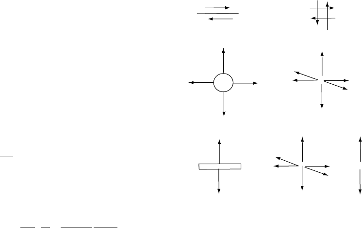
derivatives of the point force equations (Fig. 14.8).
For each case of dislocation sliding, opening
or volume collapse, the force combination must
have no net force and no net moment, because
the end result has neither linear nor rotational
acceleration. For an earthquake dislocation
model, slip is tangential to the fault plane and
in opposite directions on opposite sides. We
model the slip on the two sides in terms of oppo-
sitely directed point forces, which together form
a couple. However, a couple has a net torque, so
its sudden appearance at the time of an earth-
quake would develop an accelerating angular
momentum. To avoid this, a second couple
must be added with an equal and opposite torque
and forces at right angles to the first. The result is
the double-couple model of earthquakes.
To form the individual couples we use the
same mathematical procedure as in electro-
statics to form a dipole. Suppose that the two
surfaces of the displaced crack are a distance z
apart, which in the limit we will decrease to zero.
Let the normal to the crack area, S, be parallel to
the z-axis, and the horizontal displacement, b,in
the x-direction. The strain is b/z. Then the force
is (b/z)S. The displacement generated by the
upper and lower forces is
+
Fault Double couple
Pressurized sphere Center of dilatation
Opening crack Centre of dilatation + Force doublet
FIGURE 14.8 Point force representations of elementary
dislocations.
204 KINEMATICS OF THE EARTHQUAKE PROCESS

//FS2/CUP/3-PAGINATION/SDE/2-PROOFS/3B2/9780521873628C14.3D
–
205
– [197–223] 13.3.2008 12:37PM
u
i
ðcoupleÞ¼force G
ix
r þ
z
2
G
ix
r
z
2
¼
bS
z
G
ix
r þ
z
2
G
ix
r
z
2
¼ bS
@G
ix
@z
; ð14:9Þ
where bS is seismic moment (Eq. 14.6), and G
is the Green’s function as in Eq. (14.8). Adding a
compensating couple at right angles, of the same
strength but opposite torque, we have
u
i
ðdouble couple Þ¼bS
@G
ix
@z
þ
@G
iz
@x
: (14:10)
Here the force couple is made up of two equal
and opposite forces displaced normal to their
line of action. Seismologists use a similar con-
struction to model the opening of a crack. The
forces in this case are displaced in the direction of
opening or parallel to their line of action to form
a force doublet. Three doublets added together
at right angles make a centre of dilatation.
u
i
ðcentre of dilatationÞ¼lbS
@G
ix
@x
þ
@G
iy
@y
þ
@G
iz
@z
:
(14:11)
A centre of dilatation is used to model a
spherical region that expands. Combinations
of unequal doublets can be used to model the
expansion of ellipsoidal regions (Davis, 1986). A
much-used application of the centre of dilata-
tion solution is the Mogi model of stressing of a
volcano by a magma chamber (Anderson, 1936;
Mogi, 1958). However, in that case extra image
terms are added to the equations to cancel trac-
tions on the surface of the Earth.
Opening of a crack is modelled by combining
a centre of dilatation and a doublet oriented in
the direction of opening. The full expression is
u
i
ðtension crackÞ¼bS l
@G
ix
@x
þ
@G
iy
@y
þ
@G
iz
@z
þ2
@G
iz
@z
; ð 14:12 Þ
where l is the Lam
´
e parameter (see Section 10.2).
In general b varies over the dislocation surface
and to model finite faults the solutions are int-
egrated and may include time variation, as in
Sectio n 14.5.
Equations (14.10) to (14.12) may be general-
ized to incorporate both shear and dilatation,
u
i
¼ M
pq
@G
ip
@x
q
; (14:13)
where M
pq
is the seismic moment tensor, defined
in connection with Eq. (14.6), and given by
M
pq
¼ l
pq
b
p
S
q
þ ðb
p
S
q
þ b
q
S
p
Þ; (14:14)
where b and S are components of the vectors
b and S and
@G
ip
@x
q
is the displacement in the
i-direction from a point force in the p-direction,
differentiated in the q-direction to form a couple
or doublet.
Equation (14.13) gives the displacement in
the i-direction for an average Burgers vector,
b, dislocating a surface, S, in terms of derivatives
of the equations for displacements by elemen-
tary point forces, that is, in terms of couples and
doublets. The shear crack lying in the x–y (1–2)
plane has a moment tensor given by
M
pq
¼
00b
1
S
000
b
1
S 00
0
@
1
A
; (14: 15)
and the tension crack in the y–z (2–3) plane,
M
pq
¼
ðl þ 2Þb
1
S 00
0 lb
1
S 0
00lb
1
S
0
@
1
A
: (14:16)
Equation (14.15) demonstrates a fundamental
non-uniqueness in inverting measured displace-
ments to determine which plane has slipped
in an earthquake. Suppose that we invert
Eq. (14.13) to determine M
pq
and obtain values
corresponding to Eq. (14.15). Because of the sym-
metry of the tensor we cannot distinguish
between slip on the z plane in the x direction
and slip on the x plane in the z direction, with
M
xz
¼M
zx
. If slip occurs on the x-plane then the
z-plane is referred to as the auxiliary plane. This
is a consequence of using the point represen-
tation of an earthquake, as reconsidered in the
following section. If we invert displacement data
from a finite source we can obtain the extent and
orientation of the fault plane, i.e. M
pq
(x,y,z)
as discussed in Section 14.5. The generalized
moment tensor of an earthquake is obtained
14.3 GENERALIZED SEISMIC MOMENT 205
//FS2/CUP/3-PAGINATION/SDE/2-PROOFS/3B2/9780521873628C14.3D
–
206
– [197–223] 13.3.2008 12:37PM
by inverting Eq. (14.13) where the dynamic
Green’s function (Aki and Richards, 2002) is
used. One can rotate the tensor, as we did for
stress in Chapter 11, to obtain the fault plane
and the auxiliary plane. The moment can then
be represented as a fault plane solution for
which the plane and the slip across it are speci-
fied. For a shear dislocation, such as an earth-
quake, the trace of the moment tensor is zero,
that is, there are no opening or closing sources
(cracks).
14.4 First motion studies
The direction of the initial movement in a seis-
mic wave, at an observing station remote from
an earthquake, depends in a systematic way
on the orientation of the fault and direction of
slip relative to the station. In an infinite, uni-
form medium the pattern of compressional
(P-wave) first motions would be simple. The
medium would be divisible into four quadrants,
with one opposite pair experiencing initial
compression (motion away from the source)
and the other pair initial dilation (motion
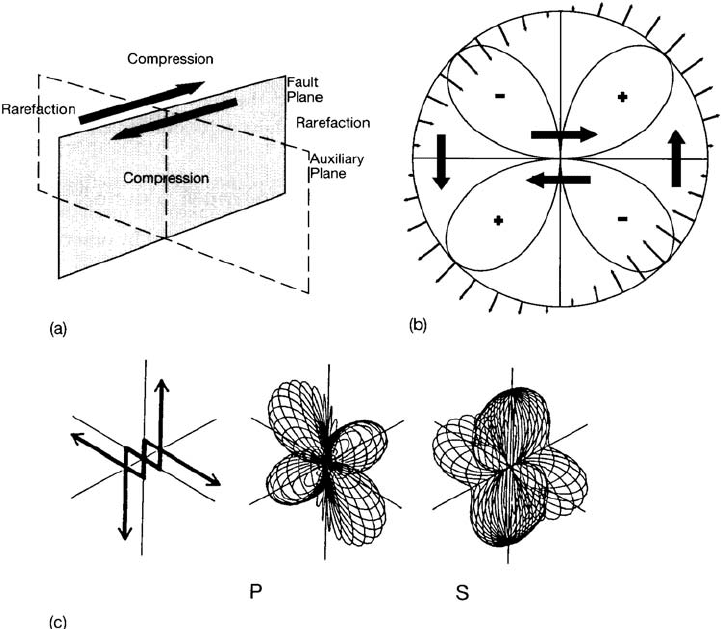
towards the source). If we consider the double
couple the heads of the force arrows will form
compressions and the tails extensions. The
boundaries of the quadrants are the fault
plane and the auxiliary plane perpendicular to
it, as in Fig. 14.9(a). The radiation pattern is
shown in Fig. 14.9(b), as viewed in a plane per-
pendicular to both the nodal (fault and auxiliary)
FIGURE 14.9 (a) Separation of compressions and rarefactions of the first motions of seismic P waves by the fault
plane and an auxiliary plane perpendicular to it. (b) P-wave radiation pattern viewed in a plane perpendicular to
the fault and auxiliary planes. At angle to this plane the amplitude is reduced by the factor cos . (c) A three-
dimensional view of the radiation pattern from a double couple point source with the orientation shown (from
Kennett, 1983, p. 90).
206 KINEMATICS OF THE EARTHQUAKE PROCESS