Shani G. Radiation Dosimetry: Instrumentation and Methods
Подождите немного. Документ загружается.

240 Radiation Dosimetry: Instrumentation and Methods
Miniature LiF:Mg,Ti (MTS-N) pellets, of diameter
1–2 mm and thickness 0.5 mm, specially designed for
dosimetry in proton radiotherapy, have been produced.
[16] The influence of dopant composition, activation
method, and cooling rate on the dose-LET response of
these TL detectors was tested. It appears that these dosi-
metric characteristics are governed mainly by the Mg-
dopant, and supralinearity and efficiency for high LET
radiation are highest for samples with the lowest content
of magnesium.
Two methods of introducing activators into bulk LiF
were tested. The first method (denoted as A), based on co-
precipitation, is typically used for producing large amounts
of LiF:Mg,Ti (in batches of more than 100 g). The second
one (method B) exploits a high-temperature treatment to
introduce dopants. Unlike method A, the latter is particu-
larly well-suited for producing a number of small samples
originating from a larger batch of raw LiF.
The dose response was described by the linearity index
f(D):
(4.19)
where
I(D) is the TL signal after exposure to a dose D and
D
0
is the reference dose. In the work of Bilski et al., D
0
1 Gy. The dose response of all samples after gamma irra-
diation was found to be supralinear. After annealing in the
PTW oven, a significant increase of f(D) was observed (see
examples in Figure 4.29a; error bars in all figures represent
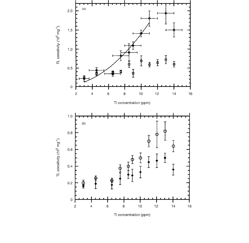
FIGURE 4.22 TL sensitivities of peaks 2–5 as a function of Ti concentration: (a) peak 5 (); peak 4 (); (b) peak 3 (); peak 2 ().
An estimate of the error in Ti concentration is shown in Figure 4.22a, as well as a quadratic fit (solid line) to the sensitivity of peak 5
as a function of Ti concentration. (From Reference [12]. With permission.)
fD()
ID()D
ID
0
()D
0
----------------------
Ch-04.fm Page 240 Friday, November 10, 2000 12:01 PM
Thermoluminescent Dosimetry 241
1 SD). All samples prepared using method B were partic-
ularly susceptible to cooling conditions. In detectors pro-
duced using method A, the differences in f(D) after differ-
ent cooling rates were much smaller—in some detectors
no difference was seen, even after the highest dose. The
Harshaw TLD-100 detectors showed practically no varia-
tion in the value of f(D) after the different cooling rates.
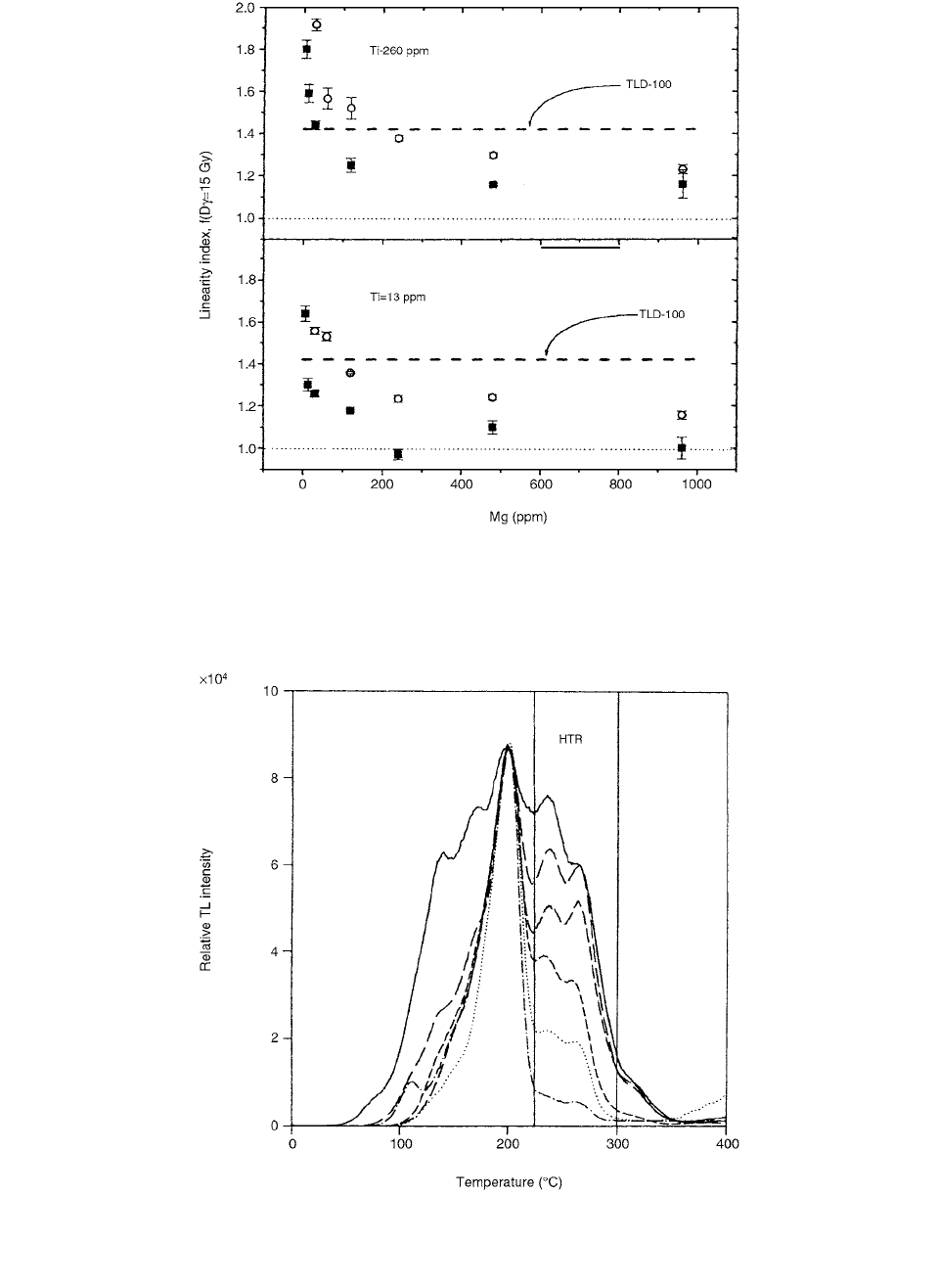
Supralinearity was found to be strongly dependent on
the concentration of magnesium. Figure 4.30 shows the
linearity index measured at a dose of 15 Gy [f(D) 15 Gy]
relative to the concentration of Mg. It can be seen that
f(D) increases as the amount of Mg decreases. Figure 4.30
also illustrates the effect of the method of activation on
supralinearity: samples prepared using method B show a
significantly higher level of supralinearity.
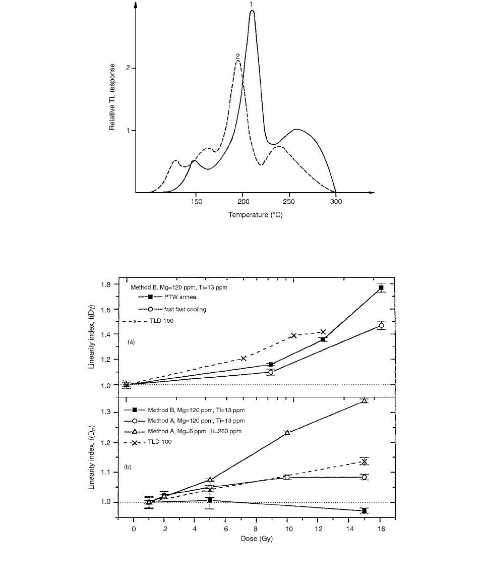
Figure 4.29b presents some examples of the measured
proton dose-response curves. The most striking result was
obtained for the 120-ppm Mg and 13-ppm Ti sample
(method B, standard concentrations), which showed no
supralinearity. A similar effect was observed in a few other
samples prepared using method B. It is somewhat surprising
that after proton exposures, B samples are less supralinear
than A samples, while after gamma irradiation the reverse
appears to be true. However, as results for samples B are
based on rather scant data, they should be treated lightly.
Other curves in Figure 4.29b represent data obtained for an
A sample with a standard concentration of dopants, for TLD-
100, and for the A sample showing the highest supralinearity.
For LET calibration, irradiations were carried out at the
Joint Institute for Nuclear Research (JINR) in Dubna with
fluoride ions in the energy range from 65 to 275 MeV amu
1
and carbon ions with energies from 100 MeV amu
1
up to
3650 MeV amu
1
. [17] Some glow curves of TLD-600 after
absorption of different radiations are shown in Figure 4.31.
The glow curves are normalized to equal height of peak 5.
The increase of high-temperature TL emission with increas-
ing LET of absorbed radiation can be seen.
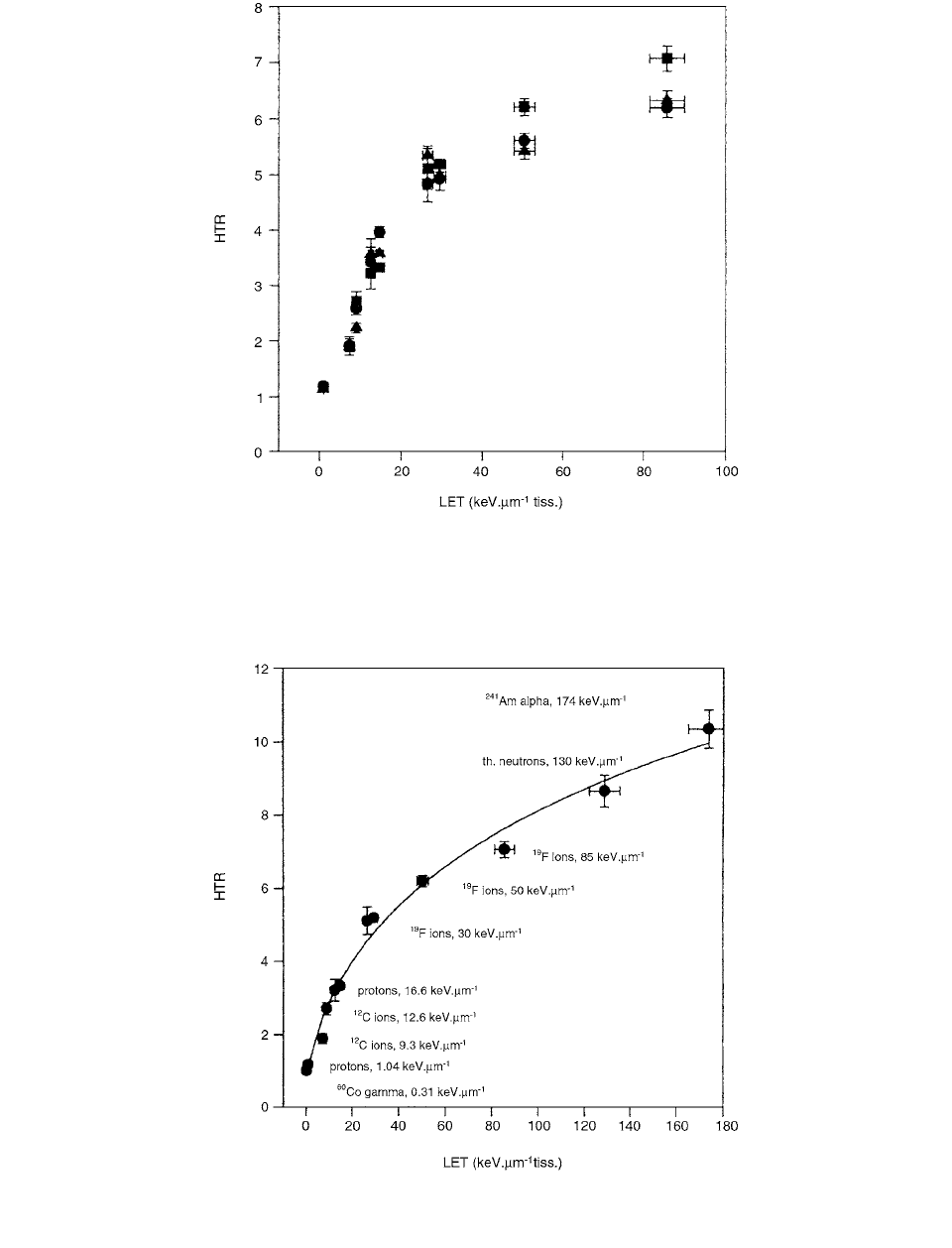
The data obtained in the LET region up to 90 keV
m
1
are plotted in Figure 4.32. The graph shows that the LET
dependence of the parameter HTR in all three dosimeter
types is quite similar. In the range up to 30 keV
m
1
in
tissue, there are no statistically significant deviations
between TLD-100, TLD-600, and TLD-700, and the
increase of HTR with LET is very steep, followed by a
saturation region where LET is greater than 30 keV
m
1
.
The relation between HTR and LET for TLD-600 for all
irradiations carried out is shown in Figure 4.33. The graph
shows that there is an increase of HTR with LET, up to a
LET of about 180 keV
m
1
.
Extruded LiF ribbons (3.1 3.1 0.9 ) and
rods (6 1 1 mm
3
) are commonly used TL dosimeters
for clinical dosimetry in radiotherapy. The dose distri-
bution in these crystals was investigated by Korn et al.
[18] in a 6-MV x-ray beam using smaller LiF TL dosim-
eter types. In the investigations with small cubes assem-
bled in form of ribbons and rods, it was found that a
higher dose was deposited in the center of the ribbons
and rods. Accordingly, it was found that TL dosimeters
in close contact with each other increase their respective
reading.
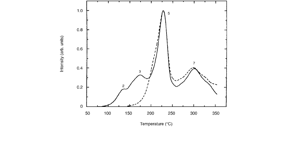
FIGURE 4.23 Glow curves of LiF:Mg, Ti single crystal after irradiation with 4.5-MeV
particles (dotted line) and after implantation with
30-keV He ions (continuous line). Both curves are normalized at the top of glow peak 5. Heating rate is 3°C s
1
. (From Reference [13].
With permission.)
mm
3
Ch-04.fm Page 241 Friday, November 10, 2000 12:01 PM
242 Radiation Dosimetry: Instrumentation and Methods
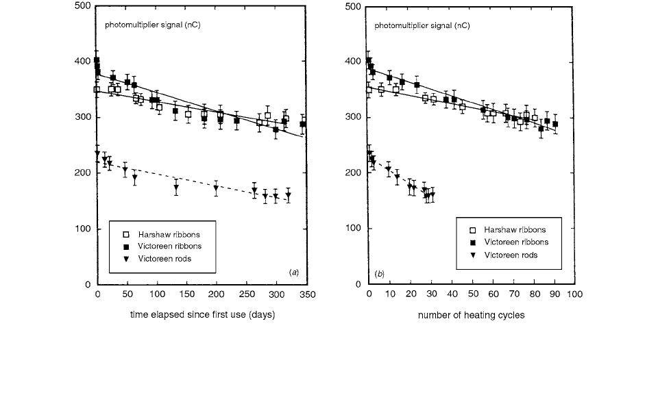
Figure 4.34a shows the dose response of the ribbons
and rods as a function of time after they have first been
used. Newly purchased Victoreen ribbons have a higher
sensitivity than those produced by Solon/Harshaw. How-
ever, Harshaw material seems to have a superior sensitivity
after prolonged use. The error bars (l SD) in Figure 4.34
show the variability of the dose response between different
crystals of one type. No significant difference could be
found between the variabilities of chips from different
manufacturers.
Figure 4.34b shows the TL response as a function of the
number of heating cycles. Each cycle includes annealing,
exposure, preread annealing, and readout of the crystals. The
dose received per temperature cycle varied between 2 cGy
and 100 cGy. Assuming an average of 50 cGy per cycle,
one can calculate a total dose administered to the crystals
of 50 Gy after 100 cycles.
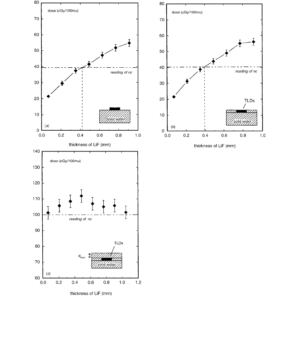
Figure 4.35 shows the dose response of XTC TL
dosimeters stacked together in the geometries illustrated
in the figures. The chips were exposed to 100 MU in a
10 10 cm
2
field with 6-MV x-rays. The measured dose
in each chip is given as a function of physical depth in
LiF. The reading of a single normal ribbon in each geom-
etry is shown by a horizontal line.
It can be seen in Figures 4.35a and b that the effective
point of measurement in a normal ribbon is not at the
geometric center of the crystal for dose determinations at
the surface (geometries A and B). In the 6-MV build-up
region, the effective point of measurement is located at
about 0.4-mm depth in the ribbon, while its geometric
center is at 0.44-mm depth. If one takes the relative elec-
tron density of LiF into account, 0.4-mm physical thick-
ness is equivalent to an effective point of measurement
about 0.9 mm below the patient’s skin for in vivo dosim-
etry. Readings taken at this depth give a reasonable dose
estimate for the deeper blood vessels, where some late
damage to the skin originates (ICRP 1991). However,
normal TLD ribbons are illustrated for the determination
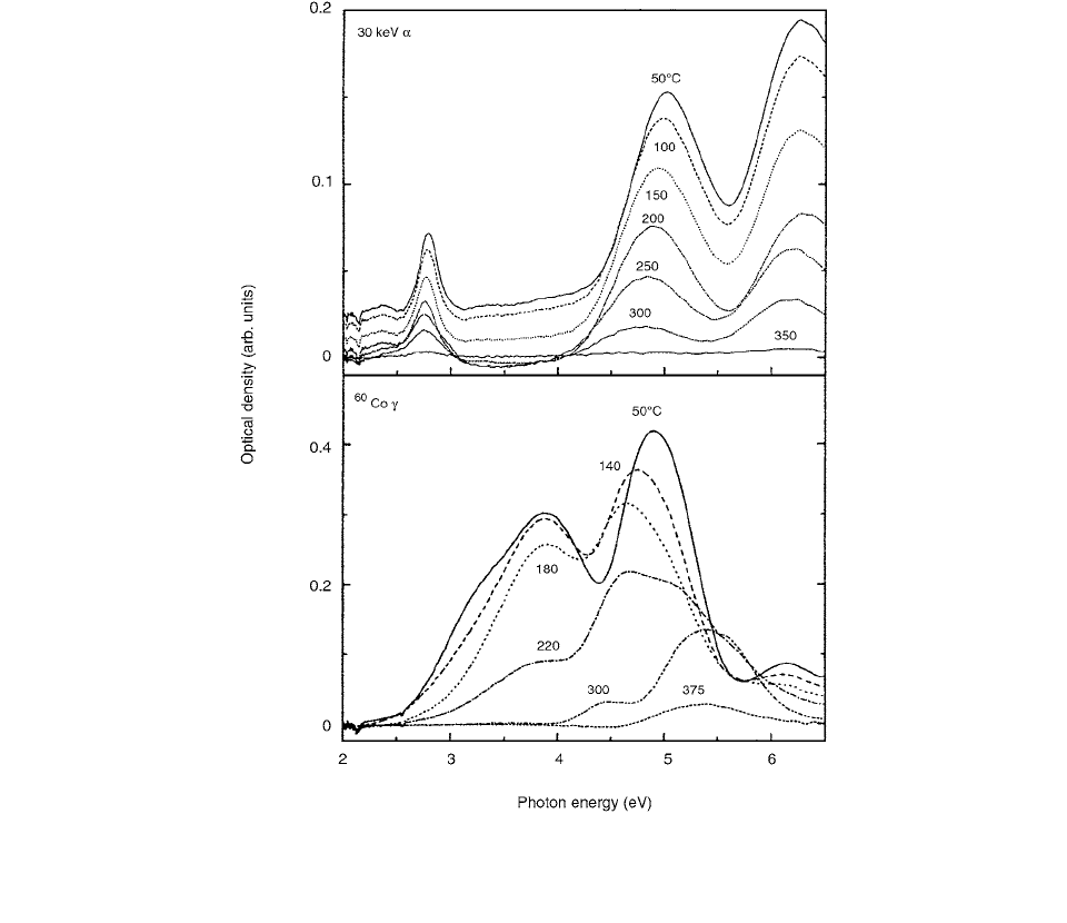
FIGURE 4.24 Optical absorption spectra of a LiF:Mg,Ti single crystal after (a) gamma-ray (D
780 Gy) and (b) 30-keV
-particle
irradiation, measured during heating at a constant heating rate of the sample of 3°C s
1
. From all plotted spectra, a spectrum at a high
temperature (400°C for the
-irradiated and 360°C for the
-irradiated) has been subtracted. (From Reference [13]. With permission.)
Ch-04.fm Page 242 Friday, November 10, 2000 12:01 PM
Thermoluminescent Dosimetry 243
of the dose to the basal cell layer located at 0.05-mm
depth, where major damage to the skin may occur.
Figure 4.35c shows the relative dose measured in 8
XTC dosimeters stacked together, one on top of each
other. This results in a stack of 1.12-mm height, which
was positioned at 1.5-cm (d
max
) depth in solid water.
Several dosimetry intercomparisons for whole-body
irradiation of mice have been organized by the European
Late Effects Project Group (EULEP). [19] These studies
were performed employing a mouse phantom loaded with
LiF thermoluminescent dosimeters. In phantom, the energy
response of the LiF TLDs differs from free in air, due to
spectral differences caused by attenuation and scatter of
x-rays. Monte Carlo calculations of radiation transport
were performed to verify the LiF TLD energy response
correction factors in phantom relative to free in air for full
scatter conditions and to obtain energy response correction
factors for geometries where full-scale conditions are not
met. For incident x-rays with HVLs in the 1 to 3.5-mm Cu
range, the energy response correction factor in phantom
deviates by 2 to 4 percent from that measured free in air.
The energy response correction factors obtained refer to
a calibration in terms of muscle tissue dose in phantom
using
60
Co gamma-rays. For geometries where full scatter
conditions are not fulfilled, the energy response correc-
tion factors are different by up to about 3 percent at
maximum from that at full scatter conditions. The depen-
dence of the energy response correction factor as a func-
tion of the position in phantom is small, i.e., about 1
percent at maximum between central and top or bottom
positions.
Meigooni et al. [20] investigated the dependence of
sensitivity and linearity of the TLD response to the flow of
nitrogen gas in the TLD reader at low-dose level. The inves-
tigations were performed using small and large LiF TLD
(TLD-100, Harshaw) chips. The differences in the physical
properties of the TLDs are encountered by using chip-factor
correction factors,
C
i,j
, obtained from the ratio of each TLD
response, TL
i,j
, to the mean response, TL
mean
, when the
whole batch is irradiated to the same dose (e.g., 100 cGy) as
(4.19)
where
(4.20)
and where
TL
BKG
is the background (reading of several
unexposed chips) and N is the total number of chips in
the batch. In dosimetry of an unknown radiation field
using several TLD chips, a mean or net response, TL
net
,
can be calculated from the responses of the individual
chips, , that were exposed to the same dose, with
correction for the background and chip factors C
ij
,
as follows
(4.21)
where F
lin
is correction for the nonlinearity of the TLD
response as a function of absorbed dose. F
lin
is defined
here as the ratio of the measured TLD response to the
predicted value for the same absorbed dose by linear
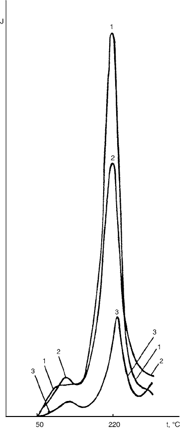
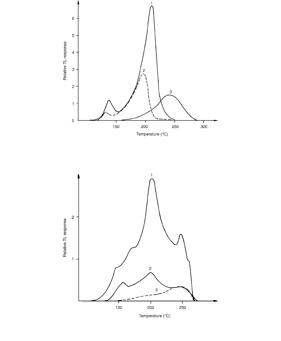
FIGURE 4.25 The glow curves for LiF (1) and for composi-
tions containing 35% (2), and 65% (3) of Li
2
CO
3
(nonlumines-
cent material). (From Reference [14]. With permission.)
C
ij
TL
ij
TL
BKG
TL
mean
--------------------------------
TL
mean
1
N
----
TL
ij
TL
BKG
()[]
i1, j1
N
TL
ij
TL
BKG
TL
net
1
n
---
TL
ij
TL
BKG
()C
ij
[]
i1, j1
n
F
lin
-----------------------------------------------------------------------------
Ch-04.fm Page 243 Friday, November 10, 2000 12:01 PM
244 Radiation Dosimetry: Instrumentation and Methods
extrapolation of the values corresponding to the doses
between 50 and 100 cGy.
The effects of nitrogen flow on the TLD responses were
measured by Meigooni et al. as a function of absorbed dose
from the gamma-rays of
137
Cs and x-rays of a 4-MV linear
accelerator. These effects were determined by comparison of
the responses of several chips (at least eight chips) that were
exposed to the same dose but read partially with and partially
without nitrogen gas flow in the TLD reader. For measure-
ments with the
137
Cs source, two slabs of Solid Water phantoms
FIGURE 4.26 Thermoluminescence glow curves of TL dosimeters. The dosimeters were irradiated with a gamma dose of 6 mGy.
Key to curves: 1, LiF (MTS-N); 2, TLD-100; 3, LiF-F. (From Reference [15]. With permission.)
FIGURE 4.27 Thermoluminescence glow curves of TL dosimeters. The dosimeters were irradiated with a volume-average alpha
dose of 24 mGy. Key to curves: 1, LiF (MTS-N); 2, TLD-100; 3, LiF-F. (From Reference [15]. With permission.)
Ch-04.fm Page 244 Friday, November 10, 2000 12:01 PM
Thermoluminescent Dosimetry 245
(20 20 4 Cm
3
) were accurately machined to accommo-
date four TLD chips at each radial distance, ranging from 0.5
to 10 cm relative to the source center.
Figure 4.36a shows the large TLD responses exposed
to doses ranging from 0.7 to 30 cGy using the gamma-
rays of a
137
Cs source, normalized to the value for the
largest dose (i.e., 22 cGy). These data were obtained by
exposing the TLD placed at a fixed distance from the
source center along the transverse bisector of the source.
The error bars in this figure reflect the range of absolute
dispersion between the individual TLD responses that were
exposed to the same dose. This figure also shows that for
FIGURE 4.28 Thermoluminescence glow curves of a LiF (MTS-N) dosimeter irradiated with a gamma dose of 1 mGy a neutron
dose of 5 mSv (curve 1) and a neutron dose of 5 mSv
a gamma dose of 1 mGy (curve 2).(From Reference [15]. With permission.)
FIGURE 4.29 Linearity index measured for selected samples and TLD-100 after exposures to: (a)
137
Cs gamma -rays, (b) modulated
proton beam-detectors placed in the middle of extended Bragg peak (PTW annealing). (From Reference [16]. With permission.)
Ch-04.fm Page 245 Friday, November 10, 2000 12:01 PM
246 Radiation Dosimetry: Instrumentation and Methods
FIGURE 4.30 Values of linearity index for gamma dose D 15 Gy plotted against Mg concentration (PTW annealing). () Method
A, (O) method B. (From Reference [16]. With permission.)
FIGURE 4.31 Glow curves from TLD-600 after irradiation with different radiations. Peak 5 is normalized to equal height. —
241
Am
alpha, 174 keV
m
1
; --- thermal neutrons, 130 keV
m
1
; --•
19
F ions, 102 keV
m
1
; ---•
19
F ions, 30 keV
m
1
; ••••
12
C ions,
12.8 keV
m
1
; -·-·-
60
Co gamma. (From Reference [17]. With permission.)
Ch-04.fm Page 246 Friday, November 10, 2000 12:01 PM
Thermoluminescent Dosimetry 247
FIGURE 4.32 High-temperature ratio HTR plotted against LET of absorbed radiation for TLD-100 (), TLD-600 (), and TLD-
700(
). (From Reference [17]. With permission.)
FIGURE 4.33 High-temperature ratio HTR plotted against LET of absorbed radiation for TLD-600. (From Reference [17]. With
permission.)
Ch-04.fm Page 247 Friday, November 10, 2000 12:01 PM
248 Radiation Dosimetry: Instrumentation and Methods
doses less than 5 cGy, the responses were dispersed by as
much as a factor of 2. This dispersion was reduced to less
than 5% when the TLDs were read with nitrogen flow in
the TLD reader. Moreover, this figure shows a profound
increase (about a factor of 2) in the mean TLD response,
with doses less than 10 cGy. This large nonlinearity has been
eliminated by using nitrogen gas. Similarly, Figure 4.36b
shows the effect of nitrogen gas flow in the TLD reader on
the responses of small chips exposed to
137
Cs gamma-rays.
As with the large chips, there was a large (about a factor
of 2) dispersion among the individual responses of small
chips when nitrogen gas did not flow through the TLD
reader. However, the mean responses of these TLD are
linear to within 10%. Although nitrogen gas reduced the
dispersion to less than 5%, it did not affect the linearity
of the TLD response.
Figure 4.37a shows the effect of nitrogen gas on the
relative sensitivity or linearity of large TLD responses
when they were exposed to 4-MV x-ray beam in the dose
range of 1–700 cGy. The relative sensitivity is defined as
the ratio of the sensitivity (TL/cGy) for a given dose to
the sensitivity for 50 cGy. The absorbed doses were mea-
sured using an ADCL-calibrated PTW ion chamber in a
polystyrene phantom.
Figure 4.37b demonstrates the effect of nitrogen gas
on the relative sensitivity of the small TLD measured
response when exposed to 4-MV x-ray beam in the dose
range of 1–700 cGy. Dose measurements were made in
the same fashion as for Figure 4.37a. These results indicate
no variation of TLD linearity and sensitivity due to nitro-
gen gas flow, which agrees with the data in Figure 4.36(b).
However, the large standard deviation (about a factor of 2)
in the TLD response at low doses was reduced to less than
5% by using nitrogen gas.
Surface dose measurements were performed by Korn
et al. [21] in the 6-MV beam of a medical linear acceler-
ator with LiF thermoluminescence dosimeters, using a
solid water phantom. TLD chips (surface area 3.17
3.17 cm
2
) of three different thicknesses (0.230, 0.099, and
0.038 g/cm
2
were used to extrapolate dose readings to an
infinitesimally thin layer of LiF.
Figure 4.38 shows the dose build-up in a solid water
phantom measured with TLD chips of three different
thicknesses. The depth in Figure 4.38 is given in g/cm
2
.
Assuming the active point of measurement to be in the
center of the each LiF chip, half of the chips thickness (in
g/cm
2
) was added to the solid water depth. The chips were
placed free-lying on the surface of a solid water slab and
covered by additional layers of solid water to give the
depth shown in Figure 4.38.
Figures 4.39 a and b show the dose build-up in LiF
TLDs of different thicknesses stacked one on top of each
other at the surface of solid water in two different geom-
etries. The TLDs were exposed to 100 mu in a 10 10-cm
2
field of 6-MV x-rays. The results given in Figure 4.39a are
for thin chips stacked in air on the surface, and the ones
FIGURE 4.34 (a) Photomultiplier signal for normal TLD ribbons and rods exposed to 100 cGy as a function of the time elapsed
since their first use. The TL signal is given as the charge collected in the photomultiplier during readout. (b) Photomultiplier signal
for normal TL ribbons and rods exposed to 100 cGy as a function of the number of heating cycles. Each cycle includes annealing,
exposure, preread annealing, and readout of the crystals. The TL signal is given as the charge collected in the photomultiplier during
readout. (From Reference [18]. With permission.)
Ch-04.fm Page 248 Friday, November 10, 2000 12:01 PM
Thermoluminescent Dosimetry 249
in Figure 4.39b are for TLDs stacked in solid water with
the top chip being flush with the solid water surface. The
increased side scatter in the second arrangement leads to
a steeper dose build-up in the chips, shown in Figure 4.39b.
The measured dose in each chip is given as a function of
physical depth in LiF in mg/cm
2
. Error bars at selected
values indicate the range of uncertainty (2 SD) for the
two types of TLDs used.
Lithium fluoride thermoluminescent dosimeter chips
(
6
LiF:Ti,Mg) were irradiated with alpha particles from an
FIGURE 4.35 (a) Dose measured with extra thin ribbons stacked one on top of each other on the surface of a solid water phantom.
The thickness of the stack of seven extra thin chips is 0.98 mm. The reading of a normal ribbon (thickness 0.89 mm) in the same
geometry is depicted as a horizontal line. (b) Dose measured with extra thin ribbons stacked one on top of each other in the surface
of a solid watre phantom. The top XTC is at the same level as the surface of the phantom. The measurement geometry is depicted
in the insert. The reading of a normal ribbon in the same geometry is shown as a horizontal line. (c) Dose measured in eight extra
thin dosimeters stacked one on top of each other at 1.5 cm (
d
max
) depth in solid water. The readings are normalized to 100 for the
reading of a single extra thin ribbon positioned at
d
max
. The reading of a normal ribbon in the same geometry shown in the insert is
depicted as a horizontal line. This is by definition 100 cGy per 100 MU at
d
max
. From Reference [18]. With permission.
Ch-04.fm Page 249 Friday, November 10, 2000 12:01 PM