Sandau R. Digital Airborne Camera: Introduction and Technology
Подождите немного. Документ загружается.

Chapter 1
Introduction
1.1 From Analogue to Digital Airborne Cameras
The use of aerial photography dates back to the middle of the nineteenth century.
By studying applications during this period, one can easily identify the level of
technology at each particular time. Continuous efforts have been made to employ
the best technologies available in either the area of photographic technique or the
methods of getting the camera airborne.
It is interesting that around 1,500 Leonardo da Vinci designed the first flying
systems and also described the process of a “Camera Obscura”, which were quite
remarkable instruments for their time and indicative of astounding foresight. Their
implementation, however, had to wait. The technical possibilities were limited, since
the components to build these systems were not yet available, owing to the lack of
differentiated natural and engineering sciences.
Three hundred years went by before further progress was made. In 1783
the first hot-air balloon was successfully flown by the Montgolfiers brothers. In
1837 Daguerre was able to produce the first images. Then in 1858 the French
Daguerrotypist and writer Gaspare Tournachon, also called Nadar, took the first
aerial photographs, over Paris from a balloon at an altitude of 300 m ( Albertz, 2001).
Balloons were used for reconnaissance purposes until the middle of the twentieth
century.
Kites were also soon utilized to take photos from an unmanned platform and in
1888 Arthur Batut in France was able to take aerial photographs in this way for the
first time. The time release for this camera was arranged by a fuse line.
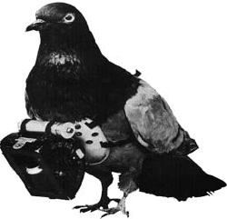
Even carrier-pigeons were used to take photographs from the air. In 1903
Dr. Julius Neubauer patented a miniature camera to be strapped to pigeons’ bod-
ies, activated by a timer mechanism (Fig. 1.1-1). Rockets were also used as carriers
of small cameras. In 1897 Alfred Nobel secured a patent for a “Photo Rocket”. As
early as 1904, Alfred Maul, an engineer from Dresden, deployed the first “Photo
Rockets”, which lifted cameras to an altitude of 800 m.
Due to progress made in the field of aviation technology, the aircraft became a
useful platform from which to take aerial photographs. The first aerial photograph
acquired from an aircraft – an oblique – was taken in 1909 over Centocelli in Italy
1
R. Sandau (ed.), Digital Airborne Camera, DOI 10.1007/978-1-4020-8878-0_1,
C
Springer Science+Business Media B.V. 2010
2 1 Introduction
Fig. 1.1-1 Carrier pigeon
with miniature camera
(source: Archive Deutsches
Museum)
by Wilbur Wright. Four years later, also in Italy, the first maps were produced from
aerial photographs (Falkner, 1994).
During World War I these cameras were developed even further and in 1915 the
first cyclical camera system for systematic serial photographs was developed by
Oskar Messter (Albertz, 1999). This system could produce photographs at a scale
of 1:10,000, covering an area of 400 square km, taken at an altitude of 3,000 m and
using no more than 1.5 h of flying time (Willmann, 1968).
After World War I the first commercial companies to make maps using aerial pho-
tographs as the major source of information were established. Colour film was soon
developed and slowly introduced into photogrammetry. In 1925, the Wild company
produced the C2 camera, which used panchromatic glass plates with a format of
10 × 15 cm. It was used as a handheld camera (Fig. 1.1-2) or installed as a
convergent dual camera system by means of a special mount.
Before the beginning of World War II the standard format in aerial photography
both for film and plates was 18 × 18 cm. During the Second World War aerial
photography underwent rapid development. Infrared film was introduced for the
purpose of detecting enemy positions.
During the 1970s, with the introduction of electronic computer-controlled tech-
nology, manual, graphical methods of map production were replaced by computer-
assisted mapping technology, which opened up tremendous possibilities. The
refinement of these developments has been an ongoing process that still contin-
ues today. The 1980s and 1990s were characterised mainly by their steady progress
in the application of computers to both the stereo plotter itself and map-making
systems in general.
Analogue aerial photography and photogrammetry were developed over many
decades and have now reached a very high standard. This very mature development
has included the introduction of large format aerial cameras, analytical and digital
stereo restitution systems and photogrammetric scanners, all of which are described
in the appropriate literature and are considered to be well known to the reader.
Examples are highly efficient analogue aerial camera systems, the Leica RC30 from
Leica Geosystems and the RMK TOP from Carl Zeiss. Today we live in a world of
digital map production and of integration of digital map data into digital databases.
1.1 From Analogue to Digital Airborne Cameras 3
Fig. 1.1-2 Use of the Wild C2 handheld aerial camera
This facilitates merging of this data with data from other sources and data that has
been generated with other remote sensing sensors, opening the opportunity to meet
new requirements and generate new products.
With the beginning of photography from space, the attempt was soon made to
eliminate film as the medium to “store” data. The problem of returning the film
to Earth proved to be complicated and onerous. To eliminate this, digital scanners
were developed, which allowed transmission of the image signal directly and in
digital form from the satellite back to Earth. Starting from single-detector whiskb-
room scanners, rapid development took place, which eventually brought us via
multi-element whiskbroom scanners to pushbroom scanners and matrix systems,
technologies which are still used today in space-based photogrammetry and remote
sensing worldwide. They allow the generation of multispectral and stereo images
with a high degree of geometric and radiometric resolution. ERTS (Earth Resource
Technology Satellite) was the first civil Earth observation satellite, launched in
1972 to acquire images from the Earth’s surface. Later this system was renamed
Landsat-1. Its sensor system MSS (Multispectral Scanner System) consisted of
a single-detector whiskbroom scanner. In 1980 the first CCD lines for satellite
image acquisition were implemented on METEOR-PRIRODA-5. The sensor system
MSU-E (Multispectral Scanning Unit-Electronic) worked in a pushbroom mode. In
1986 SPOT-1 became the first satellite to acquire time-generated stereo images via
“off-track imaging”. To generate stereo images the single line pushbroom scanner
HRV (High Resolution Visible) took two strips of images from two neighbouring
4 1 Introduction
orbits oriented towards the area which was to be photographed in stereo. MOMS-
02 was the first sensor system to use the three-line stereo method (In-Track-Stereo)
patented by Otto Hofmann in 1979 (Hofmann, 1982). In 1993 MOMS-02 was flown
on the Space Shuttle Mission STS 55 and in 1996 it was installed in the PRIRODA-
Module of the MIR Space Station. MOMS-02 used one objective lens for each
stereo channel. The first space-based mission of a Three-Line Stereo System, which
had the three stereo lines arranged on the focal plane behind one single wide-angle
objective lens, was achieved with BIRD (Bi-Spectral Infrared Detection) in 2001
(Briess, 2001). WAOSS-B (Wide-Angle Optoelectronic Stereo Scanner-BIRD) is
the modified version of WAOSS, a sensor system on the Russian Mars 96 Mission
that was designed to observe the dynamics in the atmosphere and on the sur-
face of Mars (Sandau, 1998). Unfortunately this mission failed in its initial launch
stage.
Most of the sensor systems which were developed for space-based applications
gave rise also to versions developed for use in aircraft [for example, Sandau and
Eckardt (1996)]. As a result they have been used for test purposes or/and for scien-
tific or commercial applications. Examples of a number of different German sensor
systems are:
• MEOSS: the satellite version was also used on aircraft
• MOMS-02: DPA (Digital Photogrammetry Assembly) as the airborne version
• WAOSS: WAAC (Wide-Angle Airborne Camera) as the airborne version
• HRSC: HRSC-A and HRSC-AX as airborne versions (HRSC – High Resolution
Stereo Camera – was the second German stereo camera for the failed Mars 96
Mission; it is now part of the ESA-Mission Mars Express, launched in 2003).
The development of these different techniques and sensors evolved in parallel
with the increased utilisation of aerial photographs in digital map production. If
film images are to be entered into digital databases, they must be converted into
digital form using photogrammetric scanners. Owing to the development of space-
based sensor technologies as mentioned above and the strong development trends
in other high technology fields essential to this application, it eventually became
practicable and economically feasible to go beyond scanning and replace the con-
ventional film used in aerial photography with direct digital imagery. Owing to the
many significant advances in key technological disciplines such as optics, mechan-
ics, critical materials, micro-electronics, micro-mechanics, detector and computer
technologies, signal processing, communication and navigation, we now have
financially realistic solutions for digital airborne camera systems accepted on the
market.
One concept considered for a digital camera system is to replace the conventional
film by suitable digital matrices or blocks of matrices. Another is to implement sin-
gle or multiple detector lines to create the digital image data. The first ideas along
these lines were indicated in a dissertation at the University of New Brunswick
(Derenyi, 1970). Independently from this, Otto Hoffmann developed and patented
the Three Line Concept of a Digital Airborne Camera system (Hofmann, 1982,
1.1 From Analogue to Digital Airborne Cameras 5
1988). This Three Line Concept has already been utilized in spaceborne camera sys-
tems (e.g. MOMS-02, WAOSS) and for experimental purposes in airborne cameras
(e.g. MEOSS, DPA, WAAC, HRSC).
The first commercially available digital airborne camera systems, the ADS40
from Leica Geosystems (formerly LH Systems) and the DMC from Intergraph (for-
merly Z/I Imaging), were introduced in the year 2000 at the ISPRS Congress in
Amsterdam. Other digital airborne camera systems were introduced into the market
later. Section 1.5 gives examples of commercial systems presently available on the
market.
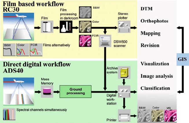
Reasonably priced digital airborne camera systems which immediately deliver
the image in digital form are only one attractive reason to switch from conventional
film cameras to digital camera systems. There are other significant economic rea-
sons for doing so as described in Fig. 1.1-3. The direct digital approach using the
digital airborne camera system eliminates the processes of developing the conven-
tional film and scanning each individual photograph into digital form. This direct
approach eliminates sources of errors and inaccuracies. Most importantly, it results
in significant savings in investment and costs related to personnel.
If the correct design concept is applied, the digital airborne camera system is
able to deliver stereo information, RGB data RGB data and IR data simultaneously
during one flight. With conventional analogue aerial cameras it is necessary to fly
the area more than once owing to different film requirements (panchromatic, colour
and FCIR), or to have multiple cameras in the aircraft.
Fig. 1.1-3 Comparison between the workflows for analogue and digital airborne cameras
6 1 Introduction
The thematic interpretation of image data can be significantly improved too,
because with digital technology the filter values required for specific applications
can be taken into consideration at the time of the design of the system.
These last two arguments in favour of a digital image generated directly by the
digital airborne camera system strongly indicate that photogrammetry and remote
sensing continue to coalesce. In many cases topographic information (e.g. digital
terrain models) is essential to expedite thematic interpretation (remote sensing) of
the data within a specific area; for photogrammetric applications, such as cartogra-
phy, the colour information is often necessary for a finished product. With the new
task of preprocessing the flight data in digital form, the interface between the com-
pany flying the imagery and the company processing the digital imagery into a final
product may now shift in such a way that the former takes over more processing
activities than ever before (see Chapter 6). The future will show whether the flying
operation becomes involved in the overall process of generating the final product,
and to what extent it is willing to do so or capable thereof.
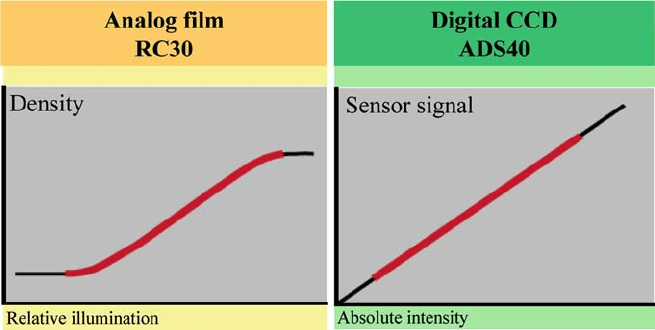
Working directly from digital imagery instead of film is opening up other very
significant possibilities in remote sensing. As can be seen from Fig. 1.1-4, film
records light rays in an s-shaped logarithmic curve. This so called DlogE curve
shows the relationship between the relative illumination (exposure) and the result-
ing density in the photograph, the density D as a function of the logarithm of the
exposure E. The term relative illumination is used because the value depends on the
exposure setting (exposure time, aperture, etc.) and the film processing (developing,
fixing, washing etc.). The CCD elements, which function as optoelectronic convert-
ers, present themselves in a linear curve. This opens up the possibility of measuring
within the spectral ranges selected by different filters. The photons hitting the detec-
tor elements within a specific, selected filter range can be counted and therefore can
be interpreted as an actual physical measuring unit.
Fig. 1.1-4 Characteristics of CCD detectors and film materials (qualitative)
1.1 From Analogue to Digital Airborne Cameras 7
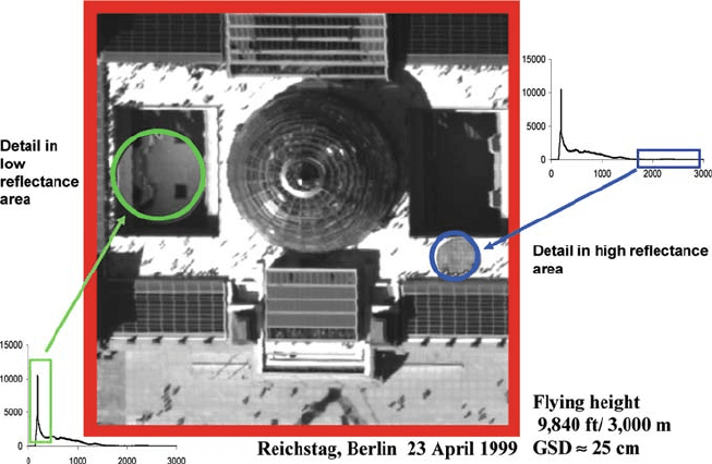
Modern electro-optical converters allow dynamic ranges of 1:4,000 (12-bit
dynamic capacity) or better. With this capability it is possible to span illumination
ranges from high reflectance to very low reflectance apparent in deep shadows in a
single image (see Fig. 1.1-5). This is also relevant in the matching procedures of dig-
ital image processing. The histograms in Fig. 1.1-5 represent the number of pixels
within the respective illumination ranges. If one “zooms” in radiometrically within
specific areas, details will be very recognisable. The high dynamic range combined
with the linear “curves” are characteristic of the quality of modern electro-optical
converters (CCD detectors) and therefore also the quality of the new digital airborne
camera systems.
The digital image technology used in modern airborne camera systems, through
appropriate system design and configuration, enables speedy transition from the
traditional photographic camera to a measuring system that captures images. This
opens up completely new application areas for digital airborne imaging sensors. The
fact that the new digital airborne cameras can be used for classical photogramme-
try as well as for airborne remote sensing creates opportunities in market segments
which so far have not been explored. This will also result in a significant increase
in the processing of such digital imagery and will result in the development of com-
pletely new “intelligent” methods to deal with such data. This trend is strongly
supported by ongoing development of and improvement to existing and newly avail-
able digital photogrammetric workstations, on which software to deal with these
digital images is being installed (Ackermann, 1995). The introduction and progress
Fig. 1.1-5 The large dynamic range of the digital sensor provides the unique opportunity to resolve
details in the dark as well as the bright areas of the image (Fricker et al., 2000)
8 1 Introduction
of digital airborne camera systems in photogrammetry and remote sensing, facil-
itated by the immense progress in diverse fields of technology, obviously has far
reaching consequences in these respective fields, which no doubt will also have a
significant influence on education, on the structure of companies active in these
fields and on the development of new job opportunities.
1.2 Applications for Digital Airborne Cameras
in Photogrammetry and Remote Sensing
Geometric data are derived with the aid of photogrammetry through measure-
ment in image material. The task of digital photogrammetry lies in the use of
methods of image processing, such as automatic point measurement, co-ordinate
transformation, image matching to derive elevation data and differential image
rectification to produce orthoimages with a cartographically compatible geometry.
Remote sensing is the contact-free imaging or measurement of objects for generat-
ing qualitative or quantitative data on their occurrence, their state or changes in their
state. Further comments and remarks can be found in Albertz (2001), Hildebrandt
(1996), Konecny (2003), Kraus (1988, 1990) and others. New digital sensor systems
can provide all data for
• determining the sizes and shapes of objects with the aid of photogrammetry,
• making the photographed content accessible to thematic evaluation through
analysis and interpretation for a specific purpose,
• determining the meaning of the recorded data through semantic evaluation.
Two parameters are particularly characteristic of photogrammetry and remote
sensing: geometric resolution, which is best expressed by ground sample distance
(GSD) in the case of digital systems, and radiometric resolution. Figure 1.2-1 shows
which spectral resolutions and GSDs are required for topographic mapping and for
selected thematic (remote sensing) applications (Röser et al., 2000). Spectral reso-
lution is shown only in qualitative terms. The following is a rough classification of
the different types of imagery and their suitability for various tasks:
• panchromatic imagery to recognise and survey the structure of the earth’s surface
and objects located on it
• multispectral imagery for making a rough classification of the chemical and
biophysiological properties of the earth’s surface and of objects situated on it
• hyperspectral imagery for identifying and making a refined classification of the
geological, chemical and biophysiological properties of the earth’s surface and of
objects situated on it.
A principle that applies to all applications is that as few spectral channels as
possible should be used.
Revisit rate is another parameter that affects the monitoring of application-
specific changes. Figure 1.2-2 shows the required revisit rates for selected
applications. Figures 1.2-1 and 1.2-2 show that topographic maps with a revisit
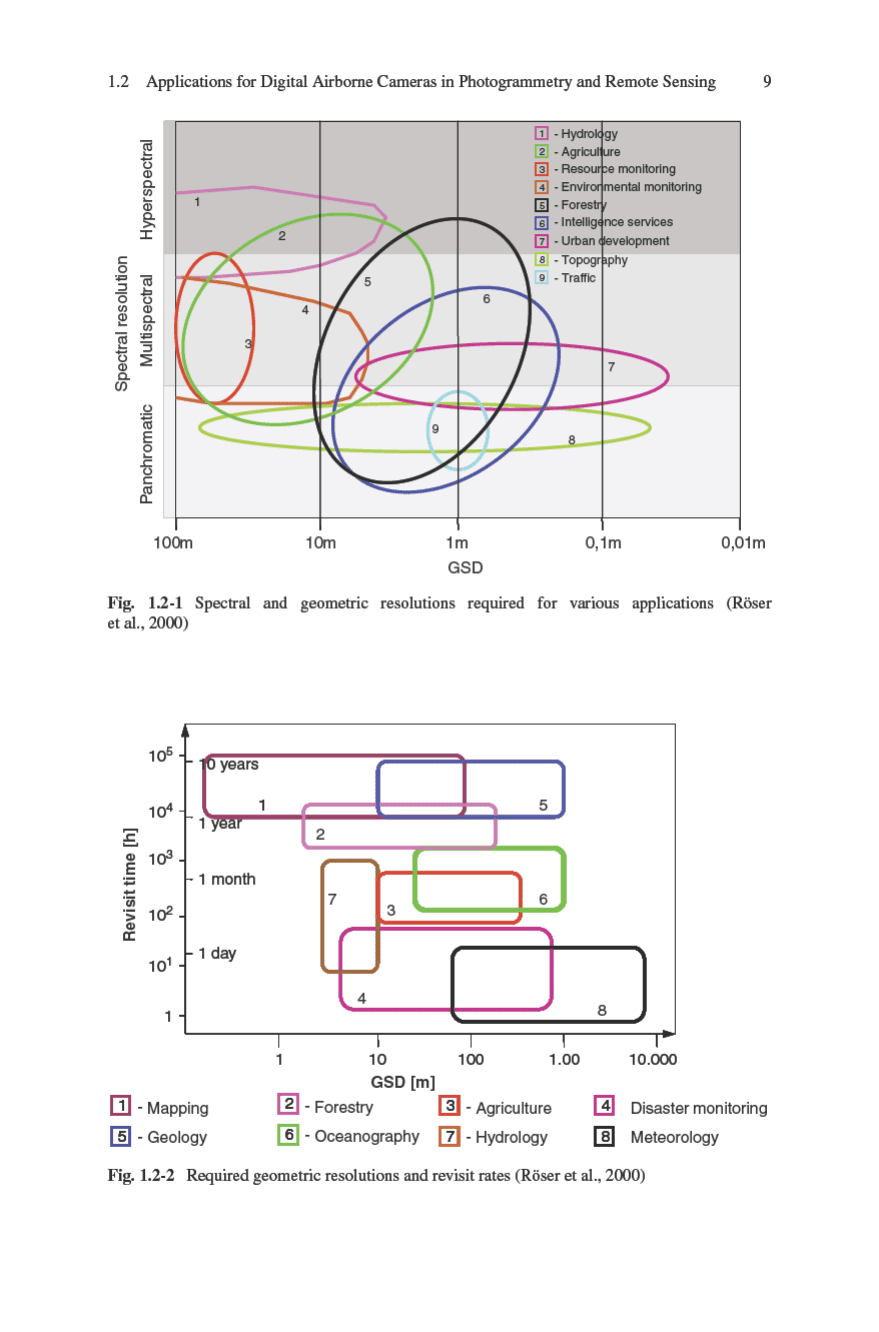

10 1 Introduction
Table 1.2-1 Ground pixel
size and achievable
planimetric mapping
scales
GSD Mapping scale
5 cm 1:500
10 cm 1:1,000
25 cm 1:2,500
50 cm 1:5,000
1 m 1:10,000
2.5 m 1:25,000
5 m 1:50,000
10 m 1:100,000
50 m 1:500,000
rate of 1–10 years with a GSD in the range of 5 cm–50 m are required. The
associated map scales for selected applications are in the 1:500–1:500,000 range
(Table 1.2-1).
The stereo angles achieved with an airborne camera influence the accuracy
of object point determination. Larger stereo angles correspond to larger potential
height resolution but may lead to problems as a result of the larger radial offset in
the image.
Experience gained with analogue airborne cameras has shown that different
stereo angles are required to achieve optimum results for topography or for object
extraction applications. It was found that large stereo angles often do not yield the
desired precision in hilly or mountainous, built-up or wooded areas. Good images
that can be readily correlated are required in digital photogrammetry. Table 1.2-2
shows the stereo angle ranges for various terrains and situations.
Table 1.2-2 Stereo angles for various applications
Topographic applications Stereo angle
Flat terrain and high height accuracy 30
◦
–60
◦
Hilly terrain 20
◦
–40
◦
Mountainous areas 10
◦
–25
◦
Object extraction applications
Natural landscape 30
◦
–50
◦
Suburban areas 20
◦
–40
◦
Urban areas 10
◦
–25
◦
Woodland 10
◦
–25
◦
Remote sensing applications give rise to a modified filter design with regard to
the spectral requirements. This is illustrated in Fig. 1.2-3.
The blue spectral channel with 460 ± 30 nm is placed in the weak absorption
range of chlorophyll of green vegetation in water or on the surface (maximum
between 430 and 450 nm). This channel is important for observing water bodies.
The 560 ± 25 nm green spectral channel lies in the reflectance maximum of green