Roll Forming Handbook / Edited by George T. Halmos
Подождите немного. Документ загружается.

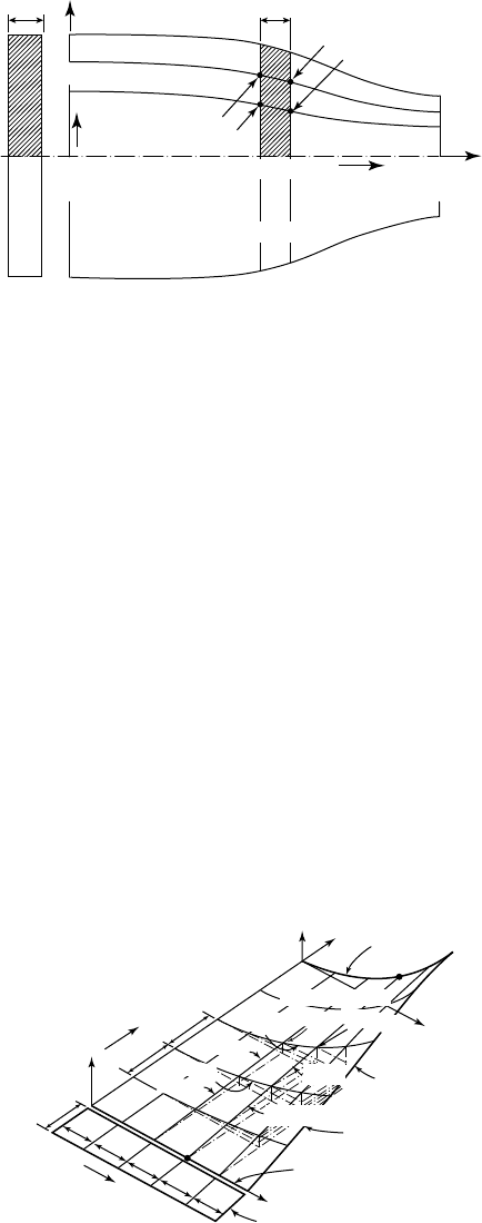
2. The forces acting on the strip in the longitudinal ( x )direction, which is equal to the sum total of
longitudinal stress occurring in it, should be equal to the tension or compression acting on the
strip between stands.
3. The forces acting on the strip in the transversal direction should satisfy the equilibrium condition.
The stress and strain componentsinthe strip,which change as it movesalong D.C.S. are analyzed by
using the elastoplastic deformation theory. The calculative procedure will be explained in the next
section. Forthe analysis and calculation, the strip is divided in the transversal direction into appropriate
numbers of elements as shown in Figure11.30.
11.4.3 GeometryofDeformed Strip and Element, and Definition of Strain
Increments Occurring in Them
The deformation process of the strip is followed up and analyzed step-by-stepasitmoves from #(i )-rolls
to # ð i þ 1 Þ -rolls. Forthis purpose, the process is divided into appropriate numbers of deformation steps.
In the following discussion, the concerned step being discussed is generally denoted as the ( k )th
deformation step or simply ( k )th step.When the analysis of deformation of the strip has been finished
from the first step to the ð k 2 1 Þ th step,the analysis of ( k )th step is performed as follows.
At first, X coordinate of the entr y(front) end of the strip,denoted by X
k þ 1
; is established (Figure11.29
and Figure 11.30). As mentioned already,the sheet strip is preliminarily divided into appropriate
Deformed Curved Surface
of Metal Sheet
∆ I
0
= ∆ X
0
:Initial Length
∆ X k :(Length at the k − th Step)
( X
k +1
, Y
k +1, j +1
)
( X
k
, Y
k , j +1
)
( X
k
, Y
k , j
)
X
k
x
X = X
2
#(i +1)− roll
X = X
1
# i − roll
X
y
j +1
y
j
X
k +1
( X
k +1
, Y
k +1, j
)
Sheet Strip
y
j +1
y
j
Y
y =Const.
y
FIGURE 11.29 Geometryofstrip which moves along the deformed curvedsurfacefrom #(i )-rolls to # ð i þ 1 Þ -rolls
under the equilibrium conditions for longitudinal and transversal forces.
Sheet Strip at Initial Stage
Position of Entrance Guide
( k –1)–th Step
( k )–th Step
Y
Y
1
Y
#1–Roll Profile
X
Z
Y
2
∆ l
k,j+1
∆ b
k+1,j
B
k+1,j
B
k+1,j +1
∆ l
k − 1,j +1
∆ l
k,j
∆ l
k,j
:Length of Strip at the k-th Step
∆ b
k,j
:Width of Element at the k-th Step
∆ X
k
∆ X
k
−
1
∆
X
0
=
∆
l
0
∆
b
0
∆
b
0
∆ b
0
∆ b
0
∆
b
0
∆ b
k,j
∆ l
k − 1,j
Z
k
Dividing Point
FIGURE 11.30 Acontinuous strip divided into narrow segments (strips) in the longitudinal direction and each
strip is divided into sheet elements in the transversal direction. Strain increments occurring in each sheet element are
calculated by the presented method and equations.
Roll Forming Handbook11-22
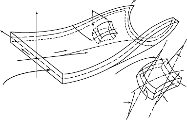
numbers of elements in the transversal direction. The coordinates of ( j )th dividing point (nodal point)
on its front cross-section at the ( k )th step is denoted as ( X
k þ 1
; j ; Y
k þ 1
; j ; Z
k þ 1
; j ). Throughthe analysis
of the ð k 2 1 Þ th step,the coordinates of the same dividing point at that step havebeen obtained and
denoted as ( X
k
; j ; Y
k
; j ; Z
k
; j )are considered to be those of the ( j )th dividing point on the rear cross-
section of the sheet strip.
From these geometrical relations, the longitudinal membrane strain increment ð d 1
xm
Þ ; occurring in
the ( j )th element of the sheet strip at the ( k )th step,iscalculated by Equation 11.3. Following
similar considerations and using the geometrical relation between twotransversally adjacent dividing
points, the transversal membrane strain increment ð d 1
ym
Þ ; occurring in the same element, is also
calculated by Equation 11.4.
ð d 1
xm
Þ
kj
¼ðD ‘
kj
2 D ‘
k 2 1
;
j
Þ = D ‘
k 2 1 ; j
ð 11: 3 Þ
ð d 1
ym
Þ
kj
¼ðD b
kj
2 D b
k 2 1 ; j
Þ = D b
k 2 1 ; j
ð 11: 4 Þ
Here,
D ‘
k ; j
¼ð D X
2
k ; j
þ D Y
2
k ; j
þ D Z
2
k ; j
Þ
1 = 2
D b
k ; j
¼ D b
k 2 1 ; j
· {1: 0 2
l
· ð d 1
xm
Þ
k ; j
}
D X
k ; j
¼ X
k ; j
2 X
k 2 1 ; j
D Y
k ; j
¼ Y
k ; j
2 Y
k 2 1 ; j
D Z
k ; j
¼ Z
k ; j
2 Z
K 2 1 ; j
l
¼ 0 : 0 , 1 : 0: membrane strain ratio.
Thus,the membranestrain increments ð d 1
xm;
d 1
ym
Þ in the x -direction (longitudinal direction), and in
y -direction (transversaldirection) occurring in the ( j )th element of the strip at the ( k )thstep aredefined. All
of the geometricalrelationships for these equations areshown in Figure 11.30. The membrane strain ration
l
is determined so as to satisfythe equilibrium of the transversalforce actingonthe element concerned.
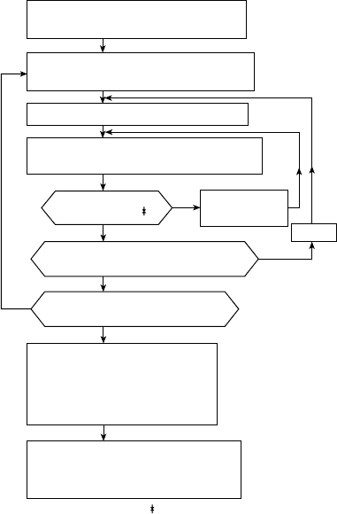
The bending strain increments ð d 1
xb
; d 1
yb
Þ in the x -direction and y -direction occurring in the ( j )th
element of the sheet strip at the ( k )th step are defined as follows by using avariable
h
.Here,
h
represents
the distancebetween the respective layer of sheet element and its neutral curved surface.Inthis analysis,
this neutral curvedsurface is considered to be the midlayerofsheet element, and the midlayercoincides
with D.C.S. (Figure 11.31).
ð d 1
xb
Þ
k ; j
¼
h
· {1= ð
z
x
Þ
k ; j
2 1 = ð
z
x
Þ
k 2 1 ; j
} ð d 1
yb
Þ
k ; j
¼
h
· {1= ð
z
y
Þ
k ; j
2 1 = ð
z
y
Þ
k 2 1 ; j
} ð 11: 5 Þ
X
X
Z
Y
y
y
x=Const.
x=Const.
( r
y
)
k –1,j
( r
x
)
k –1,j
(de
xb
)
k , j
= h • (1/( r
x
)
k , j
− 1/(r
x
)
k − 1,j
(de
yb
)
k , j
= h • (1/( r
y
)
k , j
− 1/(r
y
)
k − 1,j
( r
x
)
k , j
( r
y
)
k , j
y=Const.
y=Const.
Neutral curved surface
h
:Dis
tanc
ef
rom
neu
tral
surf
ace
h
FIGURE 11.31 Schematic illustration of bending deformation of sheet element.
Behavior of Metal Strip During Roll Forming 11-23
Here, the curvatures of the element are defined in the x -direction and in the y -direction by the following
equations, respectively.
1 =
z
x
¼ L = E ; 1 =
z
y
¼ N = G ð 11: 6 Þ
E , G , L ,and N are the “normalized parameters” of the curved surface,which are defined by the general
theoryofmathematics of geometry. If necessary, the curvatures ð
z
x ;
z
y
Þ can be calculated approximately
from the geometrical relationships between coordinates of the dividing points (nodal points) of the
elements.
By summing the incremental membrane strains and the incremental bending strains, the total strain
increments that occur in the ( j )th element of the strip at the ( k )th step are obtained. From the strain
increments, the stress increments occurring in the respective element can be calculated by using the
elastoplastic constitute equations. The details of the equations and the mathematical procedure are
described in the next section.
11.4.4 Procedure to Optimize Deformed Curved Surface (D.C.S.)
By integrating the strain and stress increments from the 1st step to the ( k )th step,the strains and stresses
accumulated in each element of the strip at the ( k )th step are obtained. This means that the distribution
and transition behavior of stress and strain components occurring in the strip can be calculated while it
moves from the first step to the ( k )th step.
The longitudinal force F
x
acting on the strip is calculated by summing the longitudinal stress
component F
x
distributed on the cross-section of the strip.Ifthe value of F
x
is not equal to the tension
or compression between stands given by the working condition, then the assumed value of X
k þ 1
is
considered to be inappropriate. Therefore, with an aim towards getting abetter approximation, the
value of X
k þ 1
is modified, following the mathematical theoryfor optimization. Then, the above-
mentioned mathematical procedurefor analyzing the deformation of the strip at the ( k )th step is
repeated. This amendment of the value of X
k þ 1
is repeated until the value of F
x
becomes equal to the
given value.
When the analysis of deformation of the strip,which moves from #(i )-rolls to # ð i þ 1 Þ -rolls, has been
finished, the total powerofdeformation
_
W ; which is dissipated in the strip deformation stage between
these tworoll stands, is calculated. The total power of deformation
_
W can be calculated by
summing the powerofdeformation dissipated in the strip (or element) while it moves from #(i )-rolls to
# ð i þ 1 Þ -rolls.
Accordingtothe theor yof“energymethod,”the total powerofdeformation
_
W should havethe
minimum value. When this requirement is satisfied, the 3-D deformed shape of the strip and the
distributing stress and strain components obtained by the above analysis are recognized as the best
approximation for those of real deformation.
When the total power of deformation
_
W is found to be other than the minimum, then the value of the
parameter “ n ; ”which is included in the shape function S ð x Þ ; is modified. Then the whole analysis of the
deformation of the sheet strip,moving from #(i )-rolls to # ð i þ 1 Þ -rollsalong the modified D.C.S. and
defined by using the modified value of “ n ; ”isrepeated. Such modification of “ n ”and the whole
procedureofanalysis is repeated until
_
W becomes minimum.
When the minimization of
_
W is attained, the analysis is finished. This analysis is performed for every
between-stand deformation wherethe results, with respect to one between-stand deformation, are used
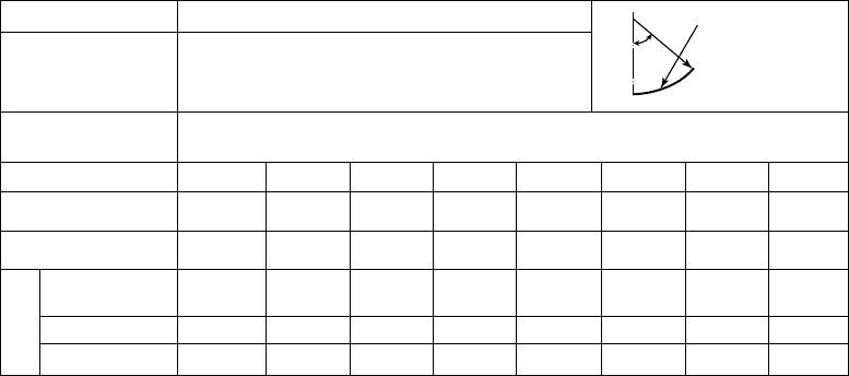
as the initial conditions for the next between-stand deformation. The block diagram of the procedureof
analysis is shown in Figure11.32.
11.4.5 Stress–Strain Relationships (Constitutive Equations)
The stress–strain relationships necessaryfor calculating stress increments are shown by Equa-
tion 11.7 , Equation 11.10, wherethe following assumptions and approximations are employed.
Roll Forming Handbook11-24
(a) The x -and y -directions are considered to coincide with the principal axes of stress and strain in
the strip.
(b) Stress component
s
z
in the z (thickness)-direction is very small and can be neglected.
(c) The strain components in the x -and y -directions are the sum totals of membrane strains and
bending strains in each direction.
Thus the following equations are introduced.
d 1
x
¼ d 1
xm
þ d 1
xb
; d 1
y
¼ d 1
ym
þ d 1
yb
ð 11: 7 Þ
Forelastic deformation, the stress–strain relationship is expressed by the following equations.
d
s
x
¼ { ð d 1
x
þ
n
· d 1
y
Þ ·E= ð 1 2
n
2
Þ }d
s
y
¼ { ð
n
· d 1
x
þ d 1
y
Þ ·E= ð 1 2
n
2
Þ } ð 11: 8 Þ
Forelastoplastic deformation, the next equation is used.
d
s
xx
¼ { ð
s
0
y
2
þ 2 P Þ · d 1
x
þð2
s
0
x
·
s
0
y
þ 2
n
·PÞ · d 1
y
} ·E= Q
d
s
y
¼ { ð 2
s
0
x
·
s
0
y
þ 2
n
·PÞ · d 1
x
þð
s
0
x
2
þ 2 P Þ · d 1
y
} ·E= Q
ð 11: 9 Þ
Profiles of # i − Roll and #(i +1)− Roll
and Their Positions
Amendment of "n"
by SimplexM
ethod
Stress and Strain Analysis of Sheet
Strip and Element
Longitudinal
Force F
k
= F
Amendment
of ∆ X
k
k = k +1
Has the Sheet Strip
reached to #(i +1)− Roll ?
Is the Total Powerof
Deformation Minimum ?
Yes
Yes
Yes
Results :
etc.
CurvedSurface
Strain Distribution
PowerofDeformation
Analysis of Deformation of Metal
Sheet between #(i +1)− Roll and
#(i +2)− Roll
F :Inter-Stand Te nsion
No
No
No
Deformed CurvedSurface of Metal
Sheet with Assumed Value of "n"
∆ X
k
is Assumed forthe K − th Step
FIGURE 11.32 Block diagram of the procedure to analyze deformation of asheet strip moving from #(i )-rolls
# ð i þ 1 Þ -rolls.
Behavior of Metal Strip During Roll Forming 11-25
where
P ¼ 2 H·
s
2
= 9 ð E 2 H Þ ; Q ¼ R þ 2 ð 1 2
n
2
Þ ·P R ¼
s
0
x
2
þ 2
n
·
s
0
x
·
s
0
y
þ
s
0
y
2 ;
s
¼ð
s
2
x
2
s
x
·
s
y
þ
s
2
y
Þ
1 = 2
s
0
x
¼ð2
s
xx
2
s
y
Þ = 3 ;
s
0
y
¼ð2
s
y
2
s
xx
Þ = 3
ð 11: 10Þ
E :Young’sModulus
n
:Poisson’s ratio
H :Strain hardening rate
11.4.6 Power of Deformation
The total power of deformation
_
W ,which is dissipated in the strip between #(i )-rolls and # (i þ 1)-rolls,
can be calculated by the next equation.
_
W ¼
X
k
X
j
X
m
D V
k ; j ; m
· { ð d W
p
Þ
k ; j ; m
þðd W
e
Þ
k ; j ; m
} ð 11: 11Þ
Here, D V
k ; j ; m
is the volume of one layer of strip element, which is obtained by dividing the strip element
in the thickness direction. In order to perform the numerical analysis, the strip or its individual element
is divided into appropriate numbers of layers in the z -(thickness) direction. The index “ m ”represents
the ( m )th layer. D V
k ; j ; m
means the volume of one layer locating at the ( j )th position in the y -direction
and ( m )th position in the z -direction at the ( k )th step of deformation. d W
p
and d W
e
denote the power
of plastic deformation and power of elastic deformation for unit volume. By summing the power of
deformation dissipated in each layer,the power of deformation dissipated in one element is obtained. By
summing the power of deformation in each element, the powerofdeformation dissipated in the strip at
the ( k )th step is calculated. Then the total power of deformation
_
W can be obtained by summing the
powerofdeformation dissipated in the sheet strip at everystep fromthe first to the last step of the
deformation between stands.
11.4.7 Some Results of Analysis
Some results obtained by the above-mentioned method will nowbediscussed with respect to roll
forming processes manufacturing round steel tubes. As an example, for a76.3 mm (3.0 in.) diameter tube
made out of 4.5 mm (0.177 in.) thick mild material, the working conditions such as the required
diameter,mechanical properties of metal, number of rolls, stands, pass-lines, and profiles of rollsare
shown in Table 11.1.
TABLE 11.1 General ChartofForming Conditions Employed for Case Study of Analysis
q
R
Roll Profile
Dimensions
Mechanical
Properties of
Metal Sheet
Forming
Conditions
Pass-Line
Bottom Line
Const.
Down-Hill
Up-Hill
Stand No.
Profile Angle q
Bending Radius R
Number of
Roll-Stands =8,
Inter-Stand
Distance =800 mm ,Speed =40m/min (mm)
Tube t4.5×φ76.3
E =21000 kgf/mm
2
,
n =0.3 , s
e
=31.5 kgf/mm
2
H=80kgf/mm
2
(Sheet t4.5× w280)
#1 #2 #3 #4 #5 #6 #7 #8
30°
229.18
− 10
+ 10
− 20
+ 20
− 30
+ 30
− 40
+ 40
− 40
+ 40
− 40
+ 40
− 40
+ 40
±0 ±0 ±0 ±0 ±0 ±0 ±0 ±0
− 40
+ 40
114.59 76.39 57.30 45.84 42.97 40.44 39.29
60° 90° 120° 150° 160° 170° 175°
Roll Forming Handbook11-26
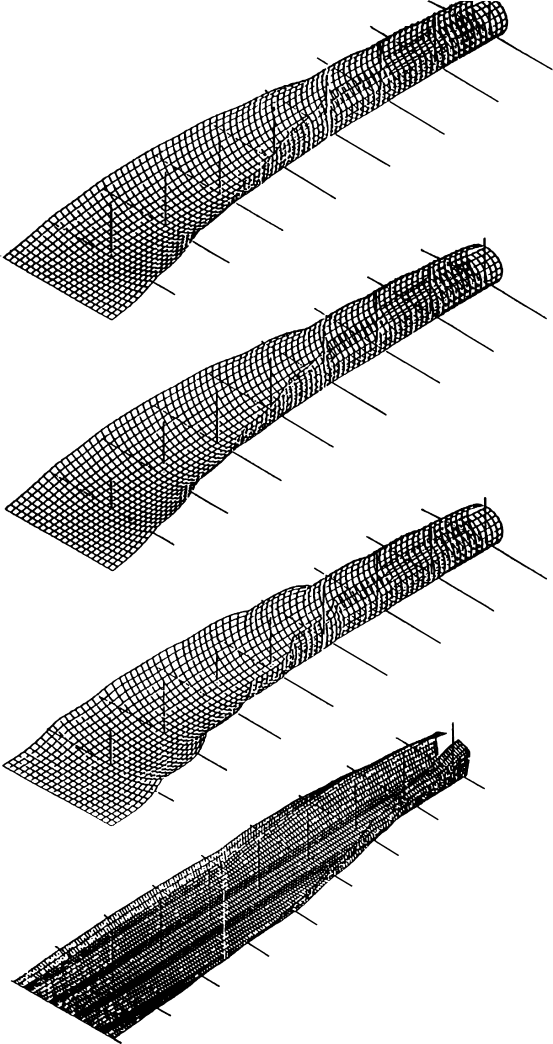
Figure11.33 shows adeformed curvedsurface of the strip being roll formed by eightpairs of rolls
under the given working conditions. The illustrated deformed curvedsurface is the optimized solution of
the analysis for this case. Similar deformed curvedsurfacesfor different working conditions can be easily
obtained. From results like this, it becomes possible to knownot only macroscopic characteristics
4.75
1.63
1.44
1.44
1.50
8.25
8.44
13.25
2.44
2.50
2.75
3.06
11.44
11.19
13.75
4.38
6.19
4.38
4.75
5.25
13.25
12.75
14.00
#1
#2
#3
#4
#5
#6
#7
#8
#1
#2
#3
#4
#5
#6
#7
#8
#1
#2
#3
#4
#5
#6
#7
#8
#1
#2
#3
#4
#5
#6
#7
#8
A=0.0
SL =400
SL =600
SL =800
kop
2
A=0.0
kop
2
A=3.0
kop
2
FIGURE 11.33 Some examples of 3-D curved surfaces of strips during roll forming of ERWpipes.
Behavior of Metal Strip During Roll Forming 11-27
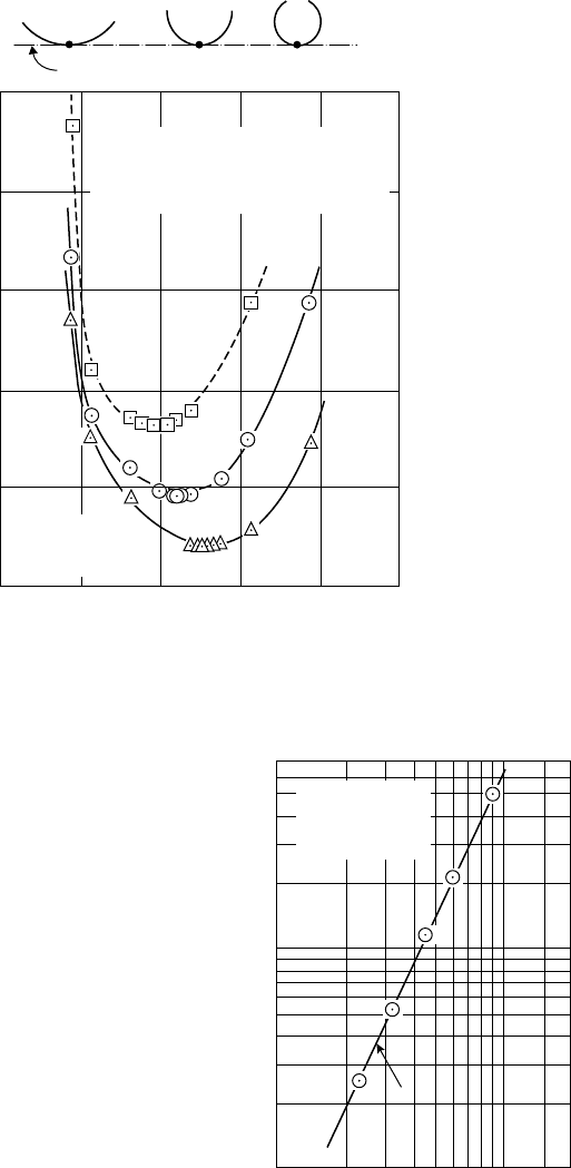
of deformation of the strip,but also detailed
featuresoflocal deformation of each portion of
it. Forinstance, the stress and strain distribut-
ing at arbitraryportions can be calculated.
Figure11.34 shows the relationship between
parameter “ n ”included in the shape function
S ð x Þ and the total powerofdeformation
_
W : The
diagram in the above the figure shows that the
total power of deformation
_
W has aminimum
value related to the change of “ n : ”This means
that the above-mentioned mathematical model
and calculation procedure, based on the energy
method, canprovideclear andreasonable
results of simulation.
Figure11.35 shows the calculated relation-
ship between
_
W and thickness of the strip ð t Þ :
The relationship can be expressed as:
_
W / t
2 : 18
ð 11: 12Þ
This result coincideswith theempirical
knowledge that the power of deformation is
02
4
Parameter n
Bottom Line (B.L.)
Total Po
werofDeformation
W
/Kgf·m/sec
112
113
114
115
116
117
6810
t 4.5 × f 76.3
Guide~#1− roll
Downhill, n =5.0, W
min
=112.40
B.L.:Horizontal, n =4.4, W
min
=112.93
Uphill, n =3.8, W
min
=113.65
FIGURE 11.34 Relationship between parameter “ n ”included in “ S ð X Þ ”and power of deformation “ W ”being
dissipated in the strip (between the entryguide and # ð 1 Þ -rolls) during roll forming of ERWpipes. The optimum
value of “ n ”gives the minimum value of “ W : ”
1
10
20
40
60
100
200
500
2
Thickness of Metal Sheet t /mm
Total Po
werofDeformation
W
min
/Kgf·m/sec
35 10 15
t × f 76.3
B.L.:Horizontal
Guide~#1− roll
W=4.24 t
2.18
FIGURE 11.35 Relationship between strip thickness “ t ”
and power of deformation “
_
W ”dissipated during forming
from entryguide to # ð 1 Þ rolls, during roll forming of ERW
pipes.
Roll Forming Handbook11-28
proportional to ( t
2.0
)invarious sheet forming
processes for which the bending deformation is
dominant co mpared with otheradditive
deformations.
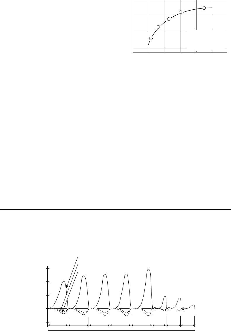
Figure11.36 shows the relationship between
optimum value of “ n ”denoted by “ n
op
”and sheet
thickness “ t : ”Itclearly shows that “ n
op
”increases
gradually as “ t ”increases. This means that, when
“ t ”islarge, the strip moving from #(i )-rolls to
# ð i þ 1 Þ -rolls, deform abruptly just in front of
the # ð i þ 1 Þ -rolls. This tendency can be observed
in actual production lines.
Figure11.37 shows some examples of the
dynamic featuresofstrains. This figure shows the
transition of the longitudinal membrane strain
1
xm
; occurring at the center,edge and intermediate position of the strip.The transition of 1
xm
is consistently calculated through the whole forming process fromthe first roll stand to the eight roll
stand.
The results indicate that large tensile strain occurs, and shows apeak value repeatedly at the edge
portion of the strip during strip deformation between everyforming stands. However,atthe roll gaps, the
transversal distribution of 1
xm
becomes nearly uniform and the value of 1
xm
becomes very small. If it
becomes excessive, this edge elongation causes edge buckling (waviness) and other product defects.
Therefore, in order to design the rollsand pass-schedules for manufacturing good products, it is
important to know the overall behavior and characteristics of 1
xm
as shown in this figure.
Thus, using the developed simulation method, it becomes possible to predict the distribution and
transition features of each strain component in the strip.Possible problems may be predicted
preliminarily,without actual trials. Therefore, it can be beneficial to predict potential problems without
using actual rolls and to modify the rollsbefore they are made.
11.5 Computerized Design System for Roll Profiles
Utilizing mathematical theoryand simulation techniques, computerized rolldesign systems are now
being developed. Such design systems are expected to be useful to develop optimal flower diagrams, roll
profiles and roll positions.
f 76.3
Guide~#1− roll
B.L.:Horizontal
5.0
4.6
4.2
3.8
0
Thickness of Metal Sheet t /mm
Optimized
Parameter
n
op
246810 12
FIGURE 11.36 Relationship between sheet thickness “ t ”
and optimized value of “ n ”for roll forming of ERWpipes.
800
− 1
0
1
2
3
× 10
− 3
Longitudinal Membrane Strain
e
xx
#1 #2 #3 #4 #5 #6 #7 #8
800 800 800 800 800 800 800
Pass− Line:Bottom Line:Horizontal
t 4.5 × f 76.3
Edge (y=120)
Midst (y=60)
Center (y=0)
FIGURE 11.37 Some calculated results on behavior of longitudinal membrane strain “ 1
xm
”during roll forming of
ERWpipes.
Behavior of Metal Strip During Roll Forming 11-29
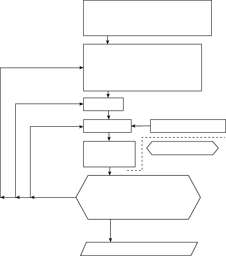
Figure11.38 showsthe flowchartofone of these advanced computerized design systems. This system
is able to design aseries of rolls to satisfy manyrequirements, including keeping the magnitude of edge
stretch (edge elongation) belowacritical value. It can also provide aseries of rollprofiles for aminimum
number of passes without inducing anyproblems. Computerized design systems like this are nowbeing
used for various roll design projects for tubes and light gage section.
The results of application are show in the following sections, where twodifferent criteria for the
optimization of rollprofiles were introduced.
1. The first criterion is for the minimization of edge stretch. The minimization of edge stretch is
attained by making the maximum values of membrane strain ð 1
xo
Þ
# i
MAX
,that occurs at the edge
portion during everyinterstand forming process, equal to each other.
2. Thesecondone is forthe equalization of drivingtorquenecessaryfor rolls, wherethe powers of
deformation(
_
W )
#i
dissipatedinmetal sheetateachinterstanddeformation state aremadeequal to
each other.
11.5.1 Flower Diagrams for Minimizing Edge Stretch
Twoseries of roll profiles designed for manufacturing round tubes withsmall t:D ( t ¼ 2 : 3 £
f
101: 6mm
or 0.090 in. thick £ 4.0 in. diameter) and large t : D ( t ¼ 4 : 5mm £
f
48.6 mm or 0.177 in. thick £ 1.91
in. diameter) are shown in Figure11.39.These rolls minimize edge stretch. The optimized allocation of
the increment of profile angle D
u
#i
to each rolland the optimized roll flowers for two cases are shown in
the figure. It should be noticed that two kinds of roll flowers are shown with the same normalized
dimension. The difference between twosets of roll flowers for small t : D and large t : D is clearly
observed. The predicted values of ð 1
xo
Þ
# i
MAX
; ¼ð1
xm
Þ
# i
MAX
,(i ¼ 1 ; 2 ; … )are also shown in Figure11.39 and
it can be known that the equalization of ð 1
xo
Þ
# i
MAX
; ð i ¼ 1 ; 2 ; … Þ is almost completely attained for each case.
Initial Data
Pass-Line
Roll-Profiles
Mathematical
Simulation
Edge Elongation
Forming Torque
Stress and Strain Distribution
etc.
Optimized Forming Process
Optimization is accomplished
Optimum Design
of Forming Mill
Optimum Design
of Pass-Line
Optimum Design
of Roll-Profiles
initial Roll-Profiles
Critical Values
VII Comparison
•
Mechanical Properties of Sheet
•
GeometryofProduct
Parameters of Forming Mill
•
Number of Roll-Stands
•
Interstand Distance
•
Others (Forming Speed etc.)
FIGURE 11.38 Conceptual illustration of computer-aided engineering and design system for roll forming.(For
design of rolls, roll positions, forming schedules, equipment, and processes.)
Roll Forming Handbook11-30
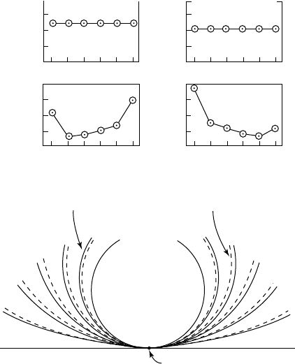
Figure11.40(a)–(c) shows the optimized increment of profile angle D
u
# i
allocated to each roll and the
optimized roll flowers for the cases when various pass lines are employed. The dimensions of the round
tube are t ¼ 4 : 5 £
f
101: 6mm(0.177 in. thick £ 4.0 in. dia). The descent of pass line height, denoted by
DH, is changed in the range from 0.0 to 0.5 XH, where H denotes the depth of the semiformed cross-
section of the strip at each roll stand. In each case, #5 rolls and #6 rolls are fixed on the horizontal line,
wherethe bottom points of the semiformed cross-section at #5 stand and #6 stand are on ahorizontal
line. From these figures, it can be seen that thereare suitable roll flowers for different pass lines in order to
minimize the edge stretch.
11.5.2 Roll Flowers for Equalized Power of Deformation
Figure11.41 shows the optimized allocation of the increment of profile angle D
u
# i
and the optimized roll
flowers for two cases when the values of t : D are small ( t ¼ 2 : 3 £
f
101: 6mmor0.090 in. thick £ 4.0 in.
diameter) and large ( t ¼ 4 : 5 £
f
48: 6mmor0.177 in. thick £ 1.91 in. diameter). The figure also shows
the powerofdeformation
_
W
# i
ð i ¼ 1 ; 2 ; … Þ has been attained almost completely.The optimized roll
flower for small t : D shown by bold lines and that for large t : D shown by broken lines are clearly
different from each other.
The effects of diameter D and wall thickness t of tubes on the powerofdeformation
_
W are summarized
as follows. When the wall thickness t is fixed,
_
W decreases as the diameter D increases. This is due to the
B.L.:Horizontal
( e
x0
)
MAX
:Maximum Value of Longitudinal
Edge Elongation
( ∆ q ):Increment of Profile Angle
#2
#3
#4
#5
#6
#1
×10
− 3
×10
− 3
t 2.3× f 101.6
t 4.5× f 48.6
4
2
0
4
2
0
#1 23456
#1 23456 #1 23456
#1 23456
30
26
22
Roll No. Roll No.
t 2.3 × f 101.6 t 4.5 × f 48.6
30
26
22
( e
x0
)
MAX
( e
x0
)
MAX
∆ q (deg)
∆ q (deg)
FIGURE 11.39 Some examples of designed roll profiles (so-called “roll flowers”) for manufacturing ERWpipes.
They are optimized so that the longitudinal membrane strain “ 1
xm
”isreduced to be minimal.
Behavior of Metal Strip During Roll Forming 11-31
