Roll Forming Handbook / Edited by George T. Halmos
Подождите немного. Документ загружается.

10.1.4 Foundations, Foundation Bolts, and Leveling
Rollforming mills usually do not require aseparate foundation if the plant has areasonably good-qualit y,
6-in (150-mm) or thicker,reinforced concrete floor.Mechanical and pneumatic presses over 20 to 30
tons (180 to 270 kN) requireseparate foundation blocks in almost all cases (see Chapter 3). Hydraulic
presses usually do not need foundation blocks.
Uncoilers and most of the other equipment in the line do not requireseparate foundations. However,
all equipment needs foundation bolts to tie it to the floor after the line has been aligned.
The equipment manufacturer usually provides an accurate foundation bolt layout and either
recommends or supplies the right type and size foundation bolts.
Usually,the centerline of the mill servesasthe main datum line for the complete roll forming line.
Distances along the datum line and the hole locations perpendicular to that line are marked on the
drawings. The datum line position is marked on the floor with atig ht string.The hole locations are
transferredfrom the drawing and are marked on the floor.
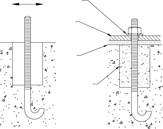
To compensate for anypossible inaccuracies, providing areasonably large clearance around each pre-
installed foundation bolt is recommended (Figure10.3). This clearanceallows for slight bending of the
bolts to accommodatethe hole location on the equipment. Oncethe equipment is aligned and leveled
and the anchor bolts are tightened, the clearance around the bolts can be filled with concrete.
Forunits which are not heavy,the expandable type of anchor bolts can be used. After aligning and
marking the bolt holes on the floor,the lightweig ht unit can be moved sideways. Then, the marked holes
can be drilled and the expandable anchor plugs inserted. Next, the equipment should be placed back,
aligned, leveled again and the bolts tightened to floor.
All equipment is accurately leveled in both directions. Leveling is frequently accomplished with
leveling screws installed in the base of the equipment. Plates and shims are often positioned underneath
the base plates of presses to supportlarger surfaces. After being leveled at the ends, long units such as the
roll forming mill beds should also be leveled at their center to avoid sagging. Height adjustment is more
critical when the ends of two machine parts, such as the split mill beds, must be accurately positioned on
the same level. Uncoilers must be accurately leveled.
Washer
Plate
Grout
Filled after
installation
FIGURE 10.3 Clearance around foundation bolts allows adjustment.
Roll Forming Handbook10-4

10.1.5 Installing Roll Forming Mills
Line installation starts with positioning the rollforming mill. All other equipment is installed to suit the
mill. First, the mill is placed on the foundation bolts. If the dimensions of the hole locations on the
drawings and the lines transmitted to the floor are the same, then the center line of the roll space in
the mill should be exactly abovethe center line drawn on the floor.
If laser or optical alignment is not available, then using asimple plumb line should be sufficiently
accurate. Alignment starts by stretching asteel wire above the center line marked on the floor.The wire is
tightened between twosolid, nonmoving points outside the twoends of the roll forming line.
The location of the wire at each end can be rechecked with the plumb,just in case the anchor points of
the wire move.The best approach is to use two plumbs. If both plumbs are just at the marked center line
on the floor,then the wire above is exactly in the right position.
One sleeve placed on the first top shaft and one on the last top shaft of the mill helps the alignment.
The sleeves have anotch or apoint marked exactly at the halfwaypoint of the roll space. For example, if
the roll spaceis24in. (60 mm), then the mark is exactly 12 in. (300 mm) on an approximately 13 in.
(330 mm) or longer sleeve. The sleeves are pushed against the shaft shoulders. The twoplumbs hanging
from the wire are positioned abovethese marks. The mill is moved sideways, back and forth until the tip
of each plumb is positioned exactly at the marks.
At this point, the mill has to be leveled in both directions and the center lines rechecked. When
everything is correct, the foundation bolts are tightened and the centering and leveling are checked again.
This completes the installation of the mill, which is the first pieceofequipment in the line.
10.1.6 Aligning and Installing Uncoilers
The mandrel of the uncoiler must be perpendicular to the center line. In the case of tight lines
(lines without aloop between the mill and the uncoiler), the wider the strip,the more critical the
perpendicularity. If the uncoiler has asliding base, then its shoulder,against which the coils are loaded,
should be aligned withthe shaft shoulders. This means that the tip of the plumb,hanging at the center
line of the mill, should be at half roll spacedistancefrom the uncoiler backplate. If the uncoiler is not
adjustable in the direction of the mandrel axis, then the uncoiler backplate or stop is usually aligned
either withthe shaft shoulder (Figure 10.4)or, in asingle purpose mill, withthe entryposition of the
strip-edge into the rolls (Figure 10.5). This will assure that wheneveracoil is loaded onto the uncoiler
and is pushed against the backplate or stop,the lead end of the strip enters directly into the rolls.
However,ifthe roll set will be interchanged, then it is still better to align the shoulder of the uncoiler with
the shoulder of the mill shaft. Aspacer against which the coils are pushed can be installed in front of the
backplate. All coils pushed against the spacer will be aligned with the correct entryposition in the mill.
If optical or laser alignment is not available, then the perpendicularityofthe mandrel can be checked
easily witha8- to 16-ft (2- to 4-m) long rigid bar,firmly attached to the mandrel. The length of the bar
depends on how highthe wire is above the floor.The bar can be attached to the mandrel by clamps or
by tack welding.Anadjustable target attached to the far end of the bar should just touch the wire
(Figure10.6).
SHAFT
SHOULDER
COIL EDGE
BACK
PLATE
FIGURE 10.4 Uncoiler backplate is aligned with the shaft shoulders.
Equipment Installation, Roll Setup, Maintenance, and Troubleshooting 10-5
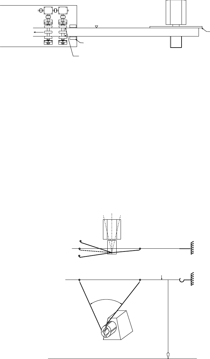
When, after about a90 8 rotation of the mandrel, the attachment on the bar touches the wire again (as
shown in Figure10.6), the mandrel is exactly perpendicular to the wire.If, after rotation, the bar is not
touching or pushing the wire,then the uncoiler is not perpendicular and the direction of the mandrel
must be slightly altered. After moving, the first “touching” position has to be established again and the
mandrel has to be rotated. This procedureshould be repeated until the bar just touches the wire in both
positions, which means that the mandrel is perpendicular to the line.
The next step is to level the mandrel, then bolt the uncoiler (or its sliding base) to the floor.
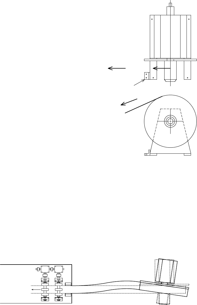
It is highly recommended to install an additional “stop plate”with twotothree anchor bolts at one
corner of the uncoiler as shown in Figure10.7.This extra heavy stop plate or angle will reduce the chance
of loosing the perpendicularitywhen the mill “jerks”the uncoiler at everystart. This sudden pulling
action has the same effect as hammering, and after several hundreds and thousands of starts the mandrel
slowly movesand rotates in the direction of the mill (Figure10.8). This effect is noticeable in
approximately 30 to 40% of the installed uncoilers. Mandrel misalignment can create waviness and other
problems in the finished products.
COIL EDGE
ENTRY
GUIDE
ROLLS TRAP THE
EDGE OF THE COIL
BACK
PLATE
FIGURE 10.5 In asingle-purpose mill, the uncoiler backplate may be aligned with the strip edge trapped in the first
pass rolls.
INCORRECT 2
INCORRECT 2
INCORRECT 1
STARTING
POSITION
INCORRECT 1
CORRECT (90° )
MILL ALLIGNMENT WIRE
LINE ON THE FLOOR
FIGURE 10.6 Asimple method to align uncoiler mandrel90 8 to the centerline.
Roll Forming Handbook10-6
10.1.7 Aligning Presses
The centerline of the press must be directly above
the centerline marked on the floor.Unfortu-
nately,most press manufacturers do not mark
thefront-to-back centerline on thepresses.
Therefore, the centerline has to be measured
and marked at both the entryand exit ends of the
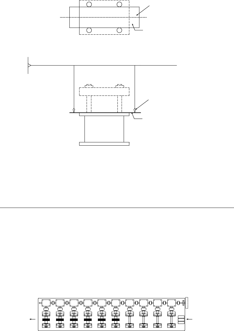
press. One or two simple templates (Figure 10.9)
protrudingfrom the press base can mark the
centerline and greatly simplify the alignment
with the wire and plumbs. Misaligned presses can
create problems, such as sections cut “off square,”
incorrect hole patterns, waviness, products stuck
in the cutoffdie, and so on.
When the press is aligned, it must be leveled
carefully in all directions and tied to the floor
with anchor bolts. If vibration pads are not used,
then the press is usually grouted (concrete placed
in the gap between the press base and the
foundation).
10.1.8 Aligning Other Equipment
in the Line
All other equipment in the roll forming line as
well as the conveyors and the transfer devices
havetobeproperly aligned, leveled, and fastened
to the floor or foundation.
10.1.9 Start-Up and Training
After anew line is installed and all service lines (electrical, air,etc.) are connected, the supplier usually
checks the installation and starts up the line. In most cases, the start-up commenceswiththe checking of
the alignment, the controls and the actions of each piece of equipment. Finally,material is fed through
the line and the operations are performed, at first, if possible, at slow speed. When everything is
satisfactory, the line speed is increased to its maximum level. This procedureisbased on the assumption
that the line has already been tested and accepted at the supplier’splant.
In most cases, the operator and the supervisor havealready participated in the acceptancetest at the
supplier’splant and it is assumed that they are already familiar with the operation. However,the in-plant
training should be extended to other personnel including: supervisors, maintenancepersonnel and
FIGURE 10.8 Constant “jerking” of the strip can dislocate uncoiler from its original position.
STOP PLATE
MILL
FIGURE 10.7 One additional stop plate can prevent the
misalignment of an uncoiler.
Equipment Installation, Roll Setup, Maintenance, and Troubleshooting 10-7
additional mill operators. The functions normally carried out by the operators, such as: mill setup,line
operation, preparation and application of forming lubricants, daily lubrication of bearings, gears, and so
on, basic troubleshooting,and others should be partofthis training.
10.2 Roll Installation and Setup
10.2.1 Considerations for Roll Installation
Asingle set of rolls may contain 10 to 250 rolls and as manyspacers. All rollsand spacers havetobe
installed at the right place, usually with more than 0.001 in. (0.025 mm) accuracy.Each roll and spacer
must havethe right identification and the operator must haveagood “setup chart” in ordertoplacethem
exactly at the right locations (see Section 5.16 to Section 5.18).
The following additional rules are applicable to most setups:
*
The pass numbers marked on the rollsand on the setup charts are usually not the same as the
stand numbers on the mill. For example, the rolls of Pass #4 are not necessarily installed on Stand
#4 (Figure 10.10).
x
x
Template
Center line
mark
Center line
Aligning Wire
Plumb
Template
FIGURE 10.9 An aligning template can simplifypress alignment with the mill centerline.
TO PRESS
STAND No.
10 987654321
654321
PASS No.
FROM UNCOILER
FIGURE 10.10 Last roll pass is installed in the last stand (in this case, Pass #6 is installed in Stand #10).
Roll Forming Handbook10-8
*
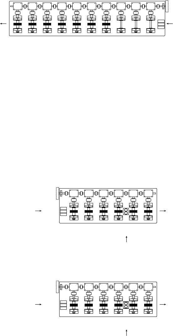
It is not unusual that suppliers decide to add additional pass(es) during the roll design and
manufacturing stage, or after the initial setup test. As aresult, some setup chartsmay show “0”
(zero)or“3A”and “3B,”or“3” and “3A”pass numbers (Figure10.11)instead of 1, 2, 3, 4, and
so on.
*
Side-rolls are sometimes assigned with apass number;for example, Pass #1, Pass #2, Pass #3, Pass
#4, Side-Roll Pass #5, Pass #6, and so on. This can mean that side-roll Pass #5 is mounted between
twostands, one holding Pass #4, and the other one #6 rolls(Figure10.12).
In some cases, side-roll stands are not numbered, or the side-roll Pass #5 mentioned above
is designated as Pass #4A and it is placed between Pass #4 and Pass #5. Because side-roll passes
are forming the sections, it is recommended that they are given asequential pass number
(as mentioned in the previous paragraph).
*
Regardlessofhow the rolls are numbered, the highest (last) pass number is placed on the last
stand, which is closest to the exit side of the mill.
TO PRESS
STAND No.
10 9876 54
0
321
43B3A3 21
PASS No.
FROM UNCOILER
FIGURE 10.11 Some suppliers mark the added or corrected passes as Pass #0 or Pass #3A, #3B and so on.
SIDE ROLL
PASS
SIDE ROLL
PASS
STAND No. 12 3456
STAND No. 12 3456
PASS No.
12 344A 56
PASS No. 12 3456 7
TO PRESS
FROM UNCOILER
TO PRESS
FROM UNCOILER
FIGURE 10.12 Side-roll pass may haveits own pass number (like #5 in the upper drawing) or aletter designation
(like #4A in the lower drawing).
Equipment Installation, Roll Setup, Maintenance, and Troubleshooting 10-9
*
The method of marking the rolls is described in Chapter 5. The unwritten rule is that the first
identification number designates the pass number and the letter “T”or“B” stands for “top”or
“bottom”shafts. The next number denotes the sequence of rolls from the shaft shoulder.For
example, 3T4 means 3rd pass, top shaft, 4th roll from the driveside, and 12B8 represents 12th
pass, bottom shaft, 8th rollfrom the driveside.
*
It is an unwritten but widely accepted standard that on each shaft, the first roll (Roll #1) or spacer
is installed first and is pushed to the “drive”side, against the shaft shoulder.The last roll or spacer
shown on the setup chart(with the highest number) is closest to the operator.
Some suppliers include the spacers in the roll numbering system. This means that the first
spacer located on the driveside is #1. Other suppliers incorrectly mark the drive-side spacer as
“IN” and the operator-side spacer as “OUT”orthey just mark the length of the spacer.
*
The very thin shims havenodesignated numbers and they are not marked. These shims are
identified by their thickness on the setup char t.
*
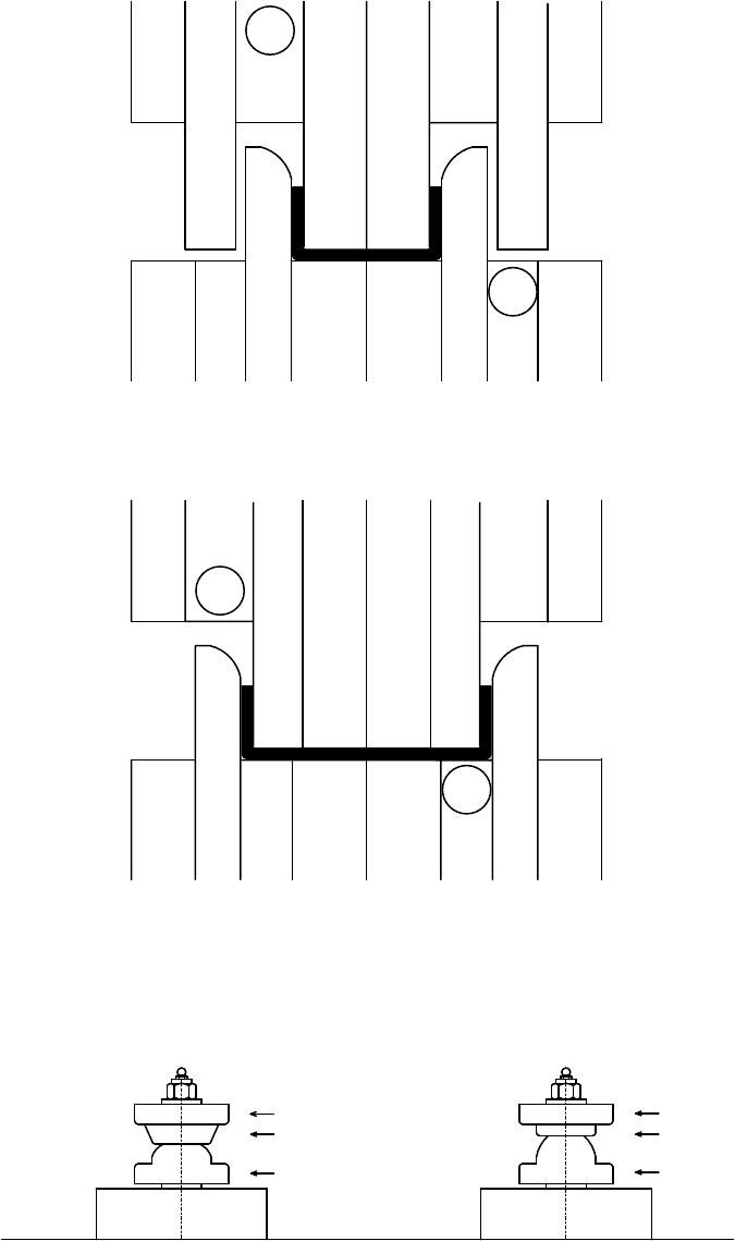
In the case of “multipurpose”rolls, the roll numbers (sequence) can be mixed up.These rolls must
be installed in the sequence shown on the setup charts (Figure10.13).
*
If aside-roll is made out of segments, these should be installed on the side-roll stand shaft
according to the rollsetup chart(Figure10.14).
10.2.2 Installing Rolls on the Shaft
The following procedures are applicable to conventional (standard) mills with shafts supported at both
ends. However,some of the principles are applicable to all types of roll forming mills.
*
Removethe left- and right-hand nuts from the top and bottom shafts.
*
Removethe bolts that fasten the outboardstands on the base.
*
Pull out the outboardstands and slide them sideways on the mill bed (if thereissufficient space)
*
Check the shafts as described in Section 10.3.5 “Mill Maintenance.”Clean each shaft; pay special
attention to removing dirt, grit, and grease accumulated at the shoulder.
*
Lubricate the shafts lightly.
*
Both flat faces of each roll and spacer must be wiped carefully to remove all dirtorgrit. All roll
markings should facethe operator unless otherwise stated on the setup chart. Most rollsare
marked in arecessed grooveonthe flat surface facing the operator.However,rollmanufacturers
sometimes makethe mistake of marking the wrongfaceofthe rolls, or sometimes the rolls are for
multipurpose use. In these cases, marks may appear on both faces.
*
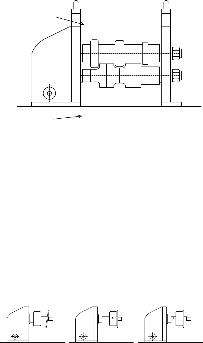
In most cases, the rolldiameters will dictate the sequence of roll installation between the top and
bottom rolls (Figure10.15).
*
If aroll is verythin (shor t), then it mayget stuck (wedged) on the shafts, unless it is pushed with
its faceexactly perpendicular to the shaft axis. The perpendicularityand ease of installation can
be achievedbypulling apreviously installed spacer or roll back against the side of the thin roll;
then both pieces can be pushed together until they are in the right position (Figure10.16).
*
Agood “clicking” sound usually indicates that the roll is fully pushed against the shoulder,ora
previously installed roll or spacer.
*
All rollsand spacers must be keyed to the shafts. Rolls without keys will rotate on the shaft and
will ruin its surface. Spacers without keys will also rotate and rub against the surface of the rolls.
Owing to constant movement, rubbing against the adjacentroll,their length will be reduced by
wear in ashortperiod of time. If the formed material has an abrasivesurface, then the spacer not
only gets shorter but it mayalso “cuts”into the rolls. Up to 0.100- to 0.150-in. (2.5- to 3.8-mm)
deep groovescan be worn into the hardened rolls by the scale which flaked offfrom the hot
rolled steel.
*
Shims (if any) identified by their thickness should be installed at the location marked on the
setup chart.
Roll Forming Handbook10-10
T2
B1
T1
B3
B2
T3
B1
T1
B3
B2
T3
T2
B5
B4
T4
T5
B7
B6
T7
T6
B5
B4
T5
T4
B7
B6
T7
T6
B8
T8
B8
T8
FIGURE 10.13 Multipurpose rolls can be placed in different locations (not following numerical sequence) as shown
in the lower drawing.
DR3
OP3
OP2
OP1
DR2
DR1
FIGURE 10.14 Setup of segmented side-rolls follows the number sequence (OP [operator side], DR [drive side]
and #1 —install first).
Equipment Installation, Roll Setup, Maintenance, and Troubleshooting 10-11
*
Installation of rollsusually starts at the last pass (closest to the press) by placing the first top and
bottom spacers or rollsonthe shafts (check carefully the “T”or“B” marks on the rolls or
spacers).
*
When all the top and bottom rolls, spacers. and shims are on the shafts, push the outboardstand
back into position. (Watch yourfingers!)
*
Placeboth the top and bottom nuts on the shaft ends and tighten the bottom nut first, then the
top nut.
*
Slide the outboardstand in and out until it is roughly in the middle of the long bearing sleeves
located in the bearing blocks of the stand.
*
Bolt the outboard stand to the mill base.
10.2.3 Checking Roll Gaps
*
Select asetup gage to suit the material thickness (maximum specified material thickness, including
“plus” thickness tolerance, coating,embossing,etc.).
*
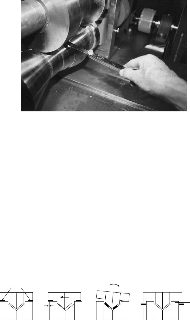
Check the horizontal gaps with feeler gages on both the driveside and operator side of the profile
(Figure 10.17). Setting screws should always be turned downwardsfor the final adjustment of the
top shaft.
SEQUENCE OF
INSTALING ROLLS
SEQUENCE OF
INSTALING ROLLS
2
B1 B2 B3 B4
B5 B6
T1 T2 T3 T4
T5 T6 T7
45 81213
13 67 91011
FIGURE 10.15 Roll diameters dictate the sequence of roll installation.
231
23
12
3
1
FIGURE 10.16 Short, thin roll (#3) wedges easily on the shaft; it can be installed with the help of an already
installed, longer roll or spacer.
Roll Forming Handbook10-12
*
Check the nonhorizontal gaps (adjust as above, check shoulder alignment or shim if required).
*
However,checking the gaps withfeeler gage alone maynot be sufficient (Figure10.18)evenifall
the rollsappear to be in the correct position.
*
Double check the gaps between rollswithamirror (Figure 10.19).
*
Check the thickness, width and other specifications of the material to be formed.
*
Enter (jog) the material through the mill, pass-by-pass.
Adjust set screws down if the roll gap is too big,and up if the pressure is too much (makethe last
adjustment always down)
*
Check the dimensions of the finished product.
*
Check deviation fromstraightness and flatness.
*
Check the product surface.
*
Check again after rolling with lubrication applied (if lube was not used during setup).
*
Check other items on the mill (e.g., entr yguide). For setting straighteners, see Section 10.2.4.
*
Check other items on the line including: length measuring devicesorcounter setting, safety
devices, uncoilers, presses, and so on.
*
Runafew pieces at normal speed and check parts beforestarting production.
FIGURE 10.17 Checking gap with afeeler gage.
FG
(a) (b) (c) (d)
FG
FG FG
FG FG
.003"
(0.075mm)
FEELER GAGES (FG)
FIGURE 10.18 After checking the gaps with feeler gages (a–c), the roll gap can still be incorrect, but it is better to
have“locked” rolls (d).
Equipment Installation, Roll Setup, Maintenance, and Troubleshooting 10-13
