Roll Forming Handbook / Edited by George T. Halmos
Подождите немного. Документ загружается.

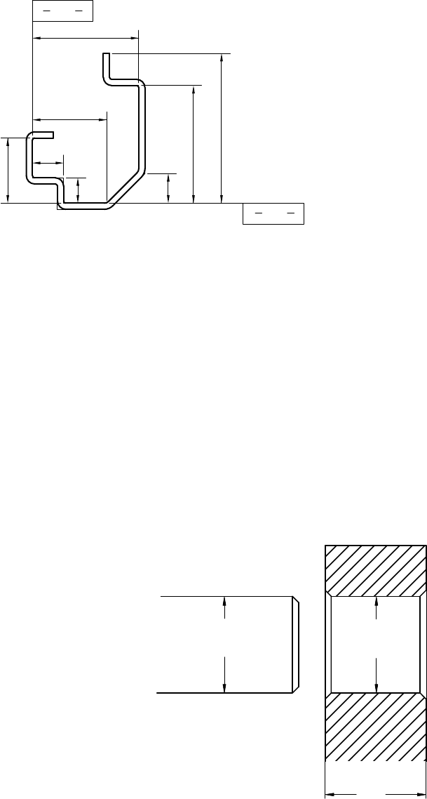
outside dimension mayalso be noted on the drawing if the partmust fit into the inside of another
component.
*
Owing to variation in material thickness, it is preferable to use the same product surfacefor
dimensioning.
*
In most cases, it is preferred to dimension roll formed components to the intersect points rather
than to the center,ortothe starting point of the radius. The distances between the intersect points
and the enclosed angle can be used for dimensioning,but maylead to mistakesand errors
(Figure 9.35).
*
So-called “base line” dimensioning is rarely used to define roll formed sections (Figure9.36).
9.6.2 Tolerancing
Tolerancecan be defined as the total amount by which aspecific dimension is permitted to vary. The
toleranceisthe difference between the maximum and minimum limits. In other words, tolerancing
specifies the total permissible variation in the size
of adimension and it basically describes the
difference between the limits of size.
“Bilateral tolerance” is atolerancethat is
expressed as plus and minus values to denote
permissible variations in both directions from
the specific size.
“Unilateraltolerance” is atolerance that
applies only in one direction from the specified
size, so that the toleranceinthe other direction
will be zero (for explanation, see Figure 9.37).
“Standardtolerances” formanufacturing
plants can be achieved at standard production
rates, at specified costs, without much extra
precaution. Therefore,changing or modifying
the equipment or tooling can influence these
established tolerances.“Standardtolerances,”
however, canbespecifiedbygovernment,
industry,orother trade standards.To manufacture
A
B
FIGURE 9.36 Base line dimensioning is not used for roll formed product.
a
±p
+0
− n
d
+m
− 0
D
FIGURE 9.37 Bilateral and unilateral tolerances on
drawings.
Roll Forming Handbook9 -24
products within these “standard tolerances”the manufacturer must havethe right qualityequipment,
tooling and properly trained personnel.
Tolerances applied to roll formed parts can be assigned into five groups.
*
Length and related tolerances
*
Tolerances on section dimensions
*
Toleranceondeviation from straightness
*
Tolerances applied to other featuressuch as holes, dimples, and so on
*
Other tolerances such as burr,appearance,and so on.
9.6.3 Length and Cutting Tolerances
The length toleranceofparts made from precut blanks depends on the accuracy of the precutting process
but rollpressure, rolldesign and other factors can alter the precut length.
If the partiscut to length in the roll forming line, then the most critical factors influencing the length
toleranceare the type and condition of the cutoffpress, the method of die accelerating and length
measuring.The length tolerancewillbealso influencedbythe speed of roll forming,roll forming tooling,
shape of the product, lubrication, location of holes, skill of operator,temperature, and afew other factors
[223]. Therefore,the partdesigner should realize that the length tolerancedepends on the capabilityof
the line used to produce the partatoptimum speed. If the partlength tolerance must be tighter than the
line capability, than either the line has to be run slower, or parts of the line (e.g., die accelerator) has to be
replaced, or acompletely new line, capable of producing parts within the specified tolerance, has to be
acquired.
Squarenessofthe cutend is seldom specifiedbecause it is expected that deviationfrom
perpendicularityofthe cutoffdie to the direction of rollforming is usually better than normally
required. There are cases, however, especially in wide panels, wherethe inaccurate mounting of die rails
or location of the press or other factors will create an “off squareness”problem.
Offsquarecuts are occasionally specified, such as in the case of gable ends or tapered or curved
products. In these cases, the angular toleranceshould be specified on the drawing.
9.6.4 Section Dimension Tolerances
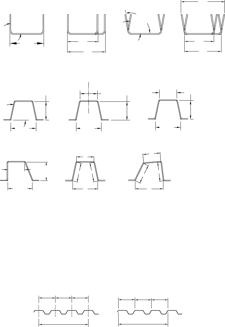
ASME Y14.5M or other national standards and the previously mentioned examples provide aguideline
for the tolerancing of roll formed profiles. Afew additional examples are shown in Figure 9.38.
Figure9.39aand Figure9.39bshow panels with multiple cells. Both the cell center distance(pitch) and
the coverage haveatolerance.
Under other conditions, the accumulated stackedtoleranceiscalculated as
t
acc
¼
ffiffiffiffiffiffiffiffiffiffiffiffiffiffiffiffiffiffiffiffiffiffiffiffiffiffiffi
t
2
1
þ t
2
2
þ t
2
3
þ ···þ t
2
n
q
In the case of roll forming, however,the toleranceoncoverage is not necessarily the mathematical
function of the accumulated tolerances of the cells. According to the interpretation used by the industry,
anycell-to-cell distanceshould be within the specified tolerance, but the toleranceofthe overall coverage
is independently specified. Figure9.39 shows adifferent wayofdimensioning the cell distance, coinciding
with the most frequently used method to measurecelldistances. The toleranceofcell distance, however,
should not be incompatible with the dimensions and tolerances shown on the section drawing.
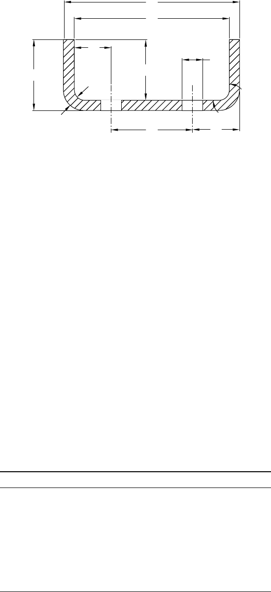
The dimensions and tolerances on the cross section of a“U” channel shown on Figure9.40 will also be
affected by the manufacturing method, tools and equipment. The dimensions will be influenced by the
factors shown in Table 9.7.
During rollforming, the material is “wrapped around” the male roll. Because the inside dimension ð a
i
Þ
cannot be changed (unless the rollissplit), the outside dimension will usually be affected by changes in
the material thickness. Forexample, a0.078-in. (2-mm) thick steel may haveacommercial thickness
Designing Products for Roll Forming 9 -25
toleranceof ^ 0.005 in. (0.13 mm). If the inside “U” channel is 1.0 in. (25.4 mm), then as aresult of
changes in material thickness, the outside dimension fluctuates between 0.990 and 1.010 in. (29.14 and
29.66 mm). This fluctuation will be in addition to the tolerancerequired for forming,springback, set up
variations, tool wear,and so on. Therefore, it is not correct to specify,for example, a ^ 0.004 in.
( ^ 0.1 mm) toleranceonthe outside dimension ð a
o
Þ when the two thicknesses of the material alone
require atoleranceof ^ 0.010 in. ( ^ 0.26 mm). Even arestrictedthickness toleranceof ^ 0.002 in.
( ^ 0.05 mm) will requirea^ 0.004 in. ( ^ 0.1 mm) tolerancefor thickness variation, plus all the
5.39
5.41
X
5.41
5.39
product within
9.38(i) dimensions
c
c
incorrect
dimensioning
1.70
2.2
2.50
product within
9.38(g) dimensions
correctly
dimensioned
dimensioning
acceptable
dimension X
not acceptable
acceptableacceptableas shown on
drawing
(a)
(e) (f) (g)
(h) (i) (j)
(b) (c)
(d)
5.40
±.01
90°
88°
92°
75°
±2°
TYP
1.70 (ref.)
insufficient
dimensions
b
b
a
a
a
a
2.20
±.01
2.50
±.01
2.50
±.01
C
L
2.20
±.01
2.50
2.20
1.70
FIGURE 9.38 Interpretation of tolerances.
Dimensioning the
center of cell
(a)
(b)
6.00±0.05
18.00±0.05
18.00±0.05
Typ. not accumulative
Typ. not accumulative
6.00±0.05
Dimensioning at the corner
of cell (seldom used)
FIGURE 9.39 Typical dimensioning of building panel cells.
Roll Forming Handbook9 -26
additional tolerances mentioned above.One must remember,however,that an extra pricemust be paid
for restrictedthickness and width or other tolerances.
9.6.5 Deviation from Straightness and Flatness
Products, which are within the specified cross-sectional tolerances, are not necessarily acceptable unless
they are within the required straightness and flatness tolerances.
Longitudinal bow, cross bow, twist and flare(see Figure4.1 and Figure10.38c–l)should be specified to
be tested on aflat surface, with one end of the product firmly held down against ahorizontal surface.
Longitudinal bowisoccasionally checked against astraight edge or twoproducts are held against each
other with bows facing each other.
Some standardsspecify the maximum height of waviness and, occasionally,the minimum distanceof
peaks from each other but in most cases edge or center waviness, ripples, and herringbone effects are
checked and judged visually.
9.6.6 Tolerances Applied to Other Features (Curvatures, Holes, Notches,
Embossments, etc.)
In case of curved(swept) products, either the radius, the apex (height of the center of the product above
astraight line between the ends), or adeviation from acurvedtemplate is specified with appropriate
tolerances. The sweep number used by the automotive industryisusually transferredinto achecking
template or fixture.
It is recommended that each drawingindicates these tolerances and often the method of measuring
them, or refers to acompanystandard.
TABLE 9.7 Factors Influencing Dimensions in Figure 9.40
Dimension Influenced by
a
i
(preferred) Tooling, springback,flare, height of leg, and dimension b
a
o
(avoid)Same as above, plus variation in material thickness
b
i
(preferred) Tooling, toleranceonstrip width, movement of coil, camber
b
o
(avoid) As b
i
plus twice the variation in material thickness
c
i
(preferred) Method of piercing, gaging, camber,and so on
c
o
(avoid) As c
i
plus variation in material thickness
e (preferred) Method piercing and gaging
r
i
(preferred) To oling and springback
r
o
(avoid) Tooling, springback and variation in material thickness
b Springback and tooling
b
o
b
i
β
a
i
d
e
a
o
c
o
c
i
r
o
r
i
FIGURE 9.40 Dimensioning cross section of a“U” channel.
Designing Products for Roll Forming 9 -27
Dimensioning and tolerancing of holes, notches, embossings, and other features may followthe ANSI
514.5M Standard. The importanceofhow the dimensions and tolerances are applied is demonstrated
in Table 9.2 to Table 9.6 on asimple roll formed “U” channel with six holes on the web.
The application of dimensioning in these examples shows how the manufacturing method and tooling
affects the wayofdimensioning and tolerancing.These examples also illustrate how the manufacturing
personnel are directed to select technology, equipment, tooling,production speed, material, and
inspection gages by the occasionally arbitraryselected application of dimensioning and tolerancing.
The “U” channel shown in the above-mentioned tables could be manufactured by forming precut
blanks or cutting the product after roll forming. The holes can be pierced individually or by two,three,
or six at atime, prior to,during,orafter forming. The tables show the correlation between manufacturing
methods, dimensioning and tolerancing.Manufacturing processes based on piercing one hole at atime
or forming the channel in apress are not included in the tables.
Tolerancewillbeinfluenced by:
“ a ”: Length toleranceofprecut line
“ b ”: Length toleranceofprepiercingpress
“ c ”: Length toleranceofrollforming line
“ d ”: Length toleranceofroll forming line (with pick-up mechanism)
“ e ”: Punch position in die set
“ f ”: Forming tolerance
“ g ”: Gaging fromcut edge
“ h ”: Gaging from hole
“ i ”: Gaging from formed edge
“ j ”: Accuracy of strip feeder
“ p ”: Uniform but accumulating, tolerances of “ e ”
“ r ”: Dimension “ r ”iseither random or related to dimension “ e ”tolerance if the first case is not
applicable, in the second case, it depends on the accuracyofthe cutoffdie equipped with pick-up
pin.
“ w ”: width tolerance(slitting)
“ x ”: camber of blank
“ y ”: camber of formed product
The top illustration in Table 9.2 showsthe manufacturing process where the “U” channel is roll formed
from precut sheets or strips having acamber.When twoadjacent holes in the web are pierced in one hit,
the location of the twoholes from the edge is usually set by gaging the pieceatthe end. The location of the
other pair of holes can be set by gaging the holes from the piercedholes or from additional end gages.
The toleranceinthe longitudinal direction will depend on the method of the gaging.During piercing,the
strip is usually pushed against one longitudinal edge; therefore, the holes in the blank will follow the
curvatureofthe precut strip.
During rollforming, however,the forming rollswill straighten out the section and the holes will be an
even distance from the formed corners.
When three holes are pierced at atime, the toleranceofthe first hole from the edge will depend on the
accuracy of end gauging,but the tolerancebetween the threeholes will be verytight. If the second rowof
three holes is gaged from the same side of the strip,then the tolerance between the tworowsofholes will
be better,but if it is gaged fromthe opposite side, then the strip width tolerancehas to be added to the
tolerancebetween the rows of holes. The holes will be in one line in the precut blank but after roll
forming they will be out of line as much as the starting strip bowed.
If six holes are pierced at the same time, then the relative location of the holes to each other can be kept
at averytight tolerance. They will be out of line again (the center hole will be closer or further from the
formed corner)bythe amount of bow in the starting strip.
Roll Forming Handbook9 -28
Table 9.3 shows the effect of the manufacturing process on the piercing tolerancewhen two or six holes
are pierced in atight line (with flying die), or in aloose line (using astrip feeder and stationarydie), with
loop between press and roll forming line, when the holes are prepierced.
Table 9.4 shows the different possibilities of punching the holes and cutting the product to length in the
line, after forming.
Table 9.5 showsthe possibilities of piercing two, three or six holes at atime after cutting the formed
channel to lengths.
Table 9.6 is based on rotary punching of strip beforeroll forming.
The examples above show that there are 17 different ways, with 17 different groups of tolerances, to
pierce and form such asimple product. Additional holes and notches and different shapes can complicate
the issue further.Therefore, if the designer expects that his or her specifications be followed in the plant,
then he or she must apply the dimensions or tolerances in away that is best suited to the manufacturing
method.
9.6.7 Other Tolerances Such as Burr and Appearance
The most difficult is to establish standards for appearance,scratch or other marks, waviness and other
characteristic that cannot be measured at the manufacturing plants. Manyofthese featuresare judged
by eye, influencedbythe available light, eyesight, anticipated reaction from aspecific customer,orother
factors.
In the case of burr,itisimportant to specify the direction of the burr on the drawings but burr size or
other featuresare seldom specified on the drawings because at most rollforming plants they can be
measured only with difficulties or not at all.
9.6.8 Influence of the Applied Tolerances on Cost
The designer’sdream is to manufactureeverything to exact dimensions or at least to verytight tolerances.
Tighttolerances can reduce product cost and simplify assembly.They can also reducewaste material and
scrap,and improvethe qualityofthe product.
Manufacturing to tight tolerances, however,usually costs more. It requires moreexpensiveand better
qualityequipment, better tooling,with morefrequent and thorough maintenance. To achieve tight
tolerance, the production speed may havetobesloweddown, and larger number of products must be
checked and possibly scrapped. More precise and expensive measuring instruments and gages are
required, operators havetobebetter trained and the whole organization must be gearedto
manufacturing products to tight tolerances.
Manufacturing products to loose tolerances, on the other hand mayalso cost more. Additional
material is wasted, assembly and erection costs can increase, and quality, most probably,willbeinferior.
(for additional comments, see Chapter 4.)
With an increased complexityofshape and hole patterns and other requirements, additional thought
should be directed to the method of dimensioning and tolerancing.Properly dimensioned and
toleranced product drawings can save from $1000 to $100,000 or moreinequipment, tooling,material
and manufacturing costs compared with the drawing of identical parts with improper dimensions and
tolerances.
Dimensions and tolerances should suit requirements, available equipment, tooling and among others,
manufacturing methods. Therefore, it is strongly recommended that the use or reference to the general
“machining tolerances” preprinted on the drafting paper is avoided.
References
[223] Halmos, G., Length tolerancefor roll formed parts, Prec. Met.,December,33–36, 1981.
[382] AISI (American Ironand Steel Institute). Appropriate Standards and Guides.
Designing Products for Roll Forming 9 -29
[420] Canadian StandardAssociation. Appropriate Standard and Guides.
[421] Dimensioning and Tolerancing,ASME National StandardY14.5A.
Further Reading
[341] Roll forming looks for ways to educate designers, Prec. Met.,March, 38–39, 1976.
[342] Production design techniques for coldroll forming, Mach. Des.,December,106–112, 1956.
[343] Halmos, G.T.1980. Design for manufacturability. Fifth International Conference on ColdFormed
Steel Structure,November 1980, St. Louis, MO.
[344] Designer’sguide to roll forming, Prec. Met.,April, 44–46, 1976.
[345] Halmos, G.T.Thin-walled structures; influenceofmanufacturing technologyondesign.
Unpublished paper.
[347]Halmos, G.,Practical design guidefor brake&rollformedproducts, Fabricator,July/August,1982.
[348] Halmos, G. 1980. Design for manufacturability. Fifth International Conference on Cold Formed
Steel Structures Proceeding,November,1980.
[349] Halmos, G., Rollforming to tight tolerances, Fabricator,March/April, 1988.
[350] Halmos, G. 1982. Practical grain bin design-manufacturing and erection considerations. Inter-
national Conference on Cold Formed Steel Structures Proceeding,November,1982.
[351] Halmos, G. 1982. Influenceofforming technologyonproduct design. Second International
Conference RotaryMetalworking Proceeding,October,p.187, 1982.
[352] Halmos, G. 1986. Rollforming to tight tolerances. SME Conference Proceeding,September 1986.
[415] Halmos, G. 1986. Designing automotive products for rollforming. SME Conference Proceeding.
[418] Yu,W.W.1979. Cold Formed Steel Structures Design Analysis Construction.Robert E. Krieger
Publishing,Huntington.
[419] Schuster,R.M. 1974. Design in Cold Formed Steel.UniversityofWaterloo Press, Waterloo.
Roll Forming Handbook9 -30

10
Equipment Installation,
Roll Setup,
Maintenance, and
Troubleshooting
GeorgeT.Halmos
Delta Engineering Inc.
10.1 Installation of Roll Forming Lines ................................. 10-1
Plant Layout
†
Service Lines (Electrical, Compressed Air,
Water etc.)
†
Space RequirementsAround the Roll Forming
Mill
†
Foundations, FoundationBolts, and Leveling
†
Installing Roll Forming Mills
†
Aligning and Installing
Uncoilers
†
Aligning Presses
†
Aligning Other Equipment
in the Line
†
Start-Up and Training
10.2 Roll Installation and Setup ............................................. 10-8
Considerations for Roll Installation
†
Installing Rolls on the
Shaft
†
CheckingRoll Gaps
†
Setting up Straighteners
10.3 Maintenanceand Spare Parts......................................... 10-14
Manuals
†
General, Preventive, Predictive Maintenance
Program
†
Lubrication Program
†
Lubrication Instruction
†
Mill Maintenance
†
MaintenanceofMechanical Presses
†
Maintenance of Hydraulic and Pneumatic Presses
†
Maintenance of Other Equipment in the Line
†
Aligning
Mill Shaft Shoulders
†
Handling and Storing of Rolls
and Tools
†
Spare Parts
10.4 Troubleshooting and Trouble Prevention ...................... 10-32
The Root of Troubles
†
Problems Created by Design and
Drawings
†
Problems Created by the Material
†
Problems
Caused by Equipment
†
Problems Caused by Tooling
†
Troubles with the Know-How of the Workforce
†
Troubleshooting
†
Trouble Prevention
10.1 Installation of Roll Forming Lines
10.1.1 Plant Layout
It is expensivetoinstall arollforming line and costly to move it; therefore, they generally stay in place for
manyyears or even decades. At that location, during the rollforming operations, thousands of coils
are loaded on to the uncoiler and millions of pieces of finished product are transportedfrom the end of
10-1
the line. To minimize material handling costs, it is essential to haveagood plant layout with an efficient
flowofmaterial.
To layout the inside of aplant properly,some of the factors listed below(among others) must be
considered:
1. Areaoccupied by the line
2. Spacerequired to operate, maintain, and repair the line safely and comfortably
3. Arearequiredfor the incoming material, finished products, and spareparts
The methods of handling coils and finished products are also importantconsiderations. Toomuch
unnecessaryspacewill increase operating costs (indirectly increasing the overhead cost, which includes
heating,maintenance, taxes, etc.). On the other hand, too little floor areawillrestrictthe efficiency of the
line, and possibly affect the safetyofthe operators. For additional details, see Chapter 8.
10.1.2 Service Lines (Electrical,Compressed Air,Water,etc.)
Rollforming lines usually require only electricityand compressed air.Water and drainage are only
needed for seldom-used water-cooled brakes or for special equipment such as resistant welders.
Each rollforming line is connected to amain electrical switch box, which contains the main
disconnectingswitch. The power(industrial voltage to the motors, 110 or 220 volts for controls, lights,
etc.) is fed through conduits from the main electrical boxtothe line. Compressed air is supplied by pipes
to the uncoiler,mill, die accelerator,and other equipment.
Installing the conduits and the pipes on the floor is less expensivethan to burythem, but they create a
safetyhazard. They can be covered with formed checkered plates, but this method is not recommended
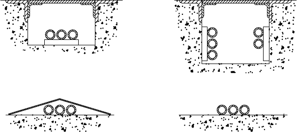
for areas with forklift truck traffic. The best waytoprevent ahazardous situation is to install the conduits
and the air pipes into trenches, covered with flat checkered plates (Figure10.1).
Electrical and air connectionsbetween the mill, the press and other components, which are not
located in the regular walking area, can be made above the floor surface. Air and water lines are
occasionally fed directly from the ceiling into the machine, but this method is not practical if cranes
are used in that area.
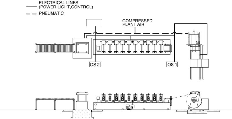
It is very helpful if the supplier of the roll forming line provides afloor layout showing the electrical,
air and other requirements well before the installation. Atypical example is shown in Figure10.2.Itis
prudent to install larger diameter conduits and air pipes than those needed at the time of installing
the line. During installation, and sometimes manyyears afterwards, additional wireshavetobepulled
through those conduits and more air could be required for the retrofit pneumatic devices.
RECOMMENDED
(a) (b)
(c) (d)
PNEUMATIC
HYDRAULIC
ELECTRICAL
RECOMMENDED
NOT RECOMMENDED
AVOID
FIGURE 10.1 Power conduits, compressed air,and hydraulic pipes run in covered trenches.
Roll Forming Handbook10-2
10.1.3 Space Requirements around the Roll Forming Mill
Arollforming line layout usually shows only the spaceoccupied by the equipment itself, but in aplant
layout additional space requirements havetobeincluded to ensure efficient and safe operation.
In the plant layout, the following space requirements should be considered:
*
Asafe walkwayfor the operators at the operator side of the line
*
Extra working space around the consoles and control panels
*
Sufficient space for paperwork (workorders,drawings, etc.)
*
An areaorabench for the hand and powertools required for operating/maintaining the line
*
Awalkway at the back of the line
*
Awalkway between the equipment to the back of long lines
*
Safe distances from electrical switch boxes, as specified by law
*
Sufficient space to ensurethat the equipment can be maintained and parts can be replaced safely
withthe aid of the required lifting equipment
*
Spacefor forklift truck traffic
*
Spacefor crane attachments
*
Coil storage space at the uncoiler
*
Finished products handling,marking,marshaling, and packaging area
*
Spacefor finished product qualitycontrol (table, lights, measuring fixtures, floor area to check
waviness, etc.)
*
Spacefor the packaging material (tote boxes, lumber,strapping,etc.) for use during production
*
Spacefor scrap and offcuts
*
Spacetostorerolls and roll-storage devices
*
Spacetostorerafts (plates) for other sections
*
Spacetostorecutoff, prepunching,and other dies
*
Spacetokeepthe equipment used for the secondaryoperations that are temporarily removed
from the line
*
Spacefor lubricant for forming
The abovespacerequirements are directly related to the rollforming line, but do not include: coil storage,
coil upenders, finished product storage, and other commonareas specified in the plant layout.
FIGURE 10.2 Typical trench layout for power and air lines.
Equipment Installation, Roll Setup, Maintenance, and Troubleshooting 10-3
