Raabe J. Hydro power - the design, use, and function of hydromechanical, hydraulic, and electrical еquipment
Подождите немного. Документ загружается.

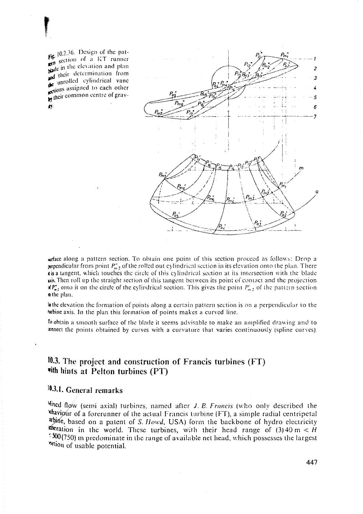
10.3.36.
Ilcsign of the pat-
''
reclii,~l
of
"
I<T runner
sc
intll~
elc~ ;,tion
and
pl:ln
11,~lr imi~tio~
from
Ice
llnr~ll~d cylindricnl vane
diolls
assigned
to each othcr
h'
lhcir
common centrc of grav-
i;r.
d~ce
along
a
pattcrn section.
To
obtain one point
of
this scction PI-ncccd
as
foIlo~>:
Drop
a
?crpcndicular from
pc~int
I.',;:?
oftlic
solltd
out cylind!-ic:ll sccrion
in
its clc\.arion onto the
pi::^^.
Therc
ais
a
tdngent,
RII~CII
touchcs tllc cjrclc of this cjlindriun? scction
at
its intersection uith thc blitdc
nis.
Then ~.oll ~p thc straight sectivn of this Iangent bclwecn its poin:
oi
contiict and the prujection
dP:,
oilto it on thc circle of the c)-li~)drical scctio~:. This gives
the
point
$:,
of illc pattcln section
n
the plan.
~a~hcclev,~tion the formation of points
long
a
curtain
pattern
sectio~l is on a pcrpendicul:ir to the
ralbine
axis.
In
the plan this formation of points makcs
a
cur~ed line.
fnohtnin
;I
smooth surfacc of the blntle
it
secnis adviqable to make
an
amplified drauing and to
snnect the points obtained by curves
with
a
cu~-\~ature that varies continuou~ly (~pline cur\es)
10.3.
The
project
and
construction
of
Francis
turbines
(FT)
with
llillts
at
Pelton
turbi~~cs
(PT)
10.3.1.
General
remarks
Yilcd
flow
(semi axial)
turbines,
named after
J.
E.
Frrrr~cis
(~+.ho
only described
the
r of
a
forerunner
of
tile actual i-rancis turbine
(FT),
a
simple radial centripet:~l
on
a
patent
of
S.
Ilo\r.d,
USA)
forn:
thc
backbone of
hydro
clec~~*icity
the world.
Thcsc
turbines,
will1
their
head
range of
(3)40
m
c
H
'm(750)
m
predominate
in
lllc range
of
availnbie
net
11e;id.
ivhich
possesses
the
largest
''nion
of
usable potential.
Thcrclorc
;n
prcsc~l
t
FTs attain tlic 1;lrgcst output.
as
icen in the crilolples
of
Fif.
3.4.16,
iind tile Fipi~rcs 10.3.1 to Fig.
10.3.8,
nl~ich :~tt;~ins now
a
value
800
h.lM1
or
1
108
000
lips. This is tlie largc.;t output
a
olle-stagc t~irb~~~,~:,
Co~itrary to the
;!xiill
turbine with ils perccolngc rciiction up to
80(90)"/.,
taSb
n
rcactioil ~nacliine, has a
percentage
rcnction of about 50%0.
In rormer
days
it
\v\.ns
and
is still found in micro plo~its,
heeds
dowtl
to
3
rn.
20
yea$
the 6cll~viour of a
FT
tnodcl with
4
h1W
undcr 650 tn head
\,V~S
tested
by
ulir/,
11,
at
Pqrtlieneo, rl~~triil (owner: Vor:irlbergcr Illwerke).
LK
Alcier
[10.153]
madr
a
Smo
study
of
thc construction
of
a
IT
in
;I
splierical casing for
1000
m
head,
which
work
as
;l
pump-turbine (sce Fig.
10.3.9).
The
4
turbines with the highest head
ofthist)
in
scrvice
operate in Rosshag, Austria
11,,,
=
670
m.
P
=
58
MW,
n
=
750
rp
Fig. 10.3.10, desig11t.d by Escher Vv'yss and Andritz, Austria. At the moment Sulzer
Wyss have
an
order for two
1110
MW
FTs
for the Austrian plmt
liiilrslir~rr
f10.1911
i,
,
-
I
I.
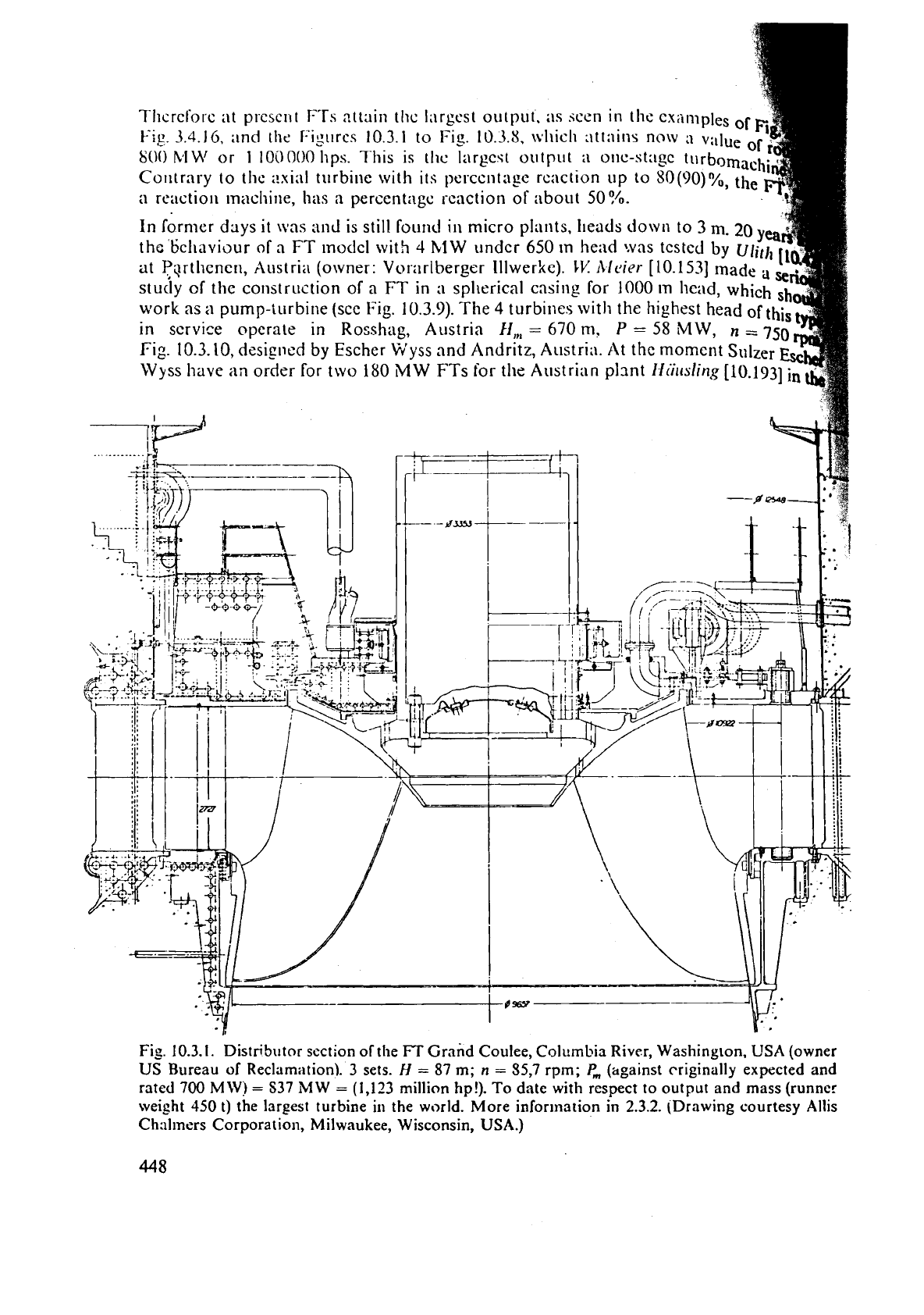
Fig.
10.3.1.
Distributor section of the
FT
Grand Coulee, Columbia River, Washington.
USA
(owner
US Bureau of Reclamation).
3
sets.
H
=
87
m;
n
=
35,7
rpm;
P,
(against
criginally expected and
rated
700
MW?
=
S37
MW
=
(1,123
million hp!). To date with respect to output and mass (runner
weight
450
t)
the largest turbine in the world. More infortnation in
2.3.2.
(Drawing courtesy Allis
Ch:ilmers Corporation, Milwaukee, Wisconsin, USA.)
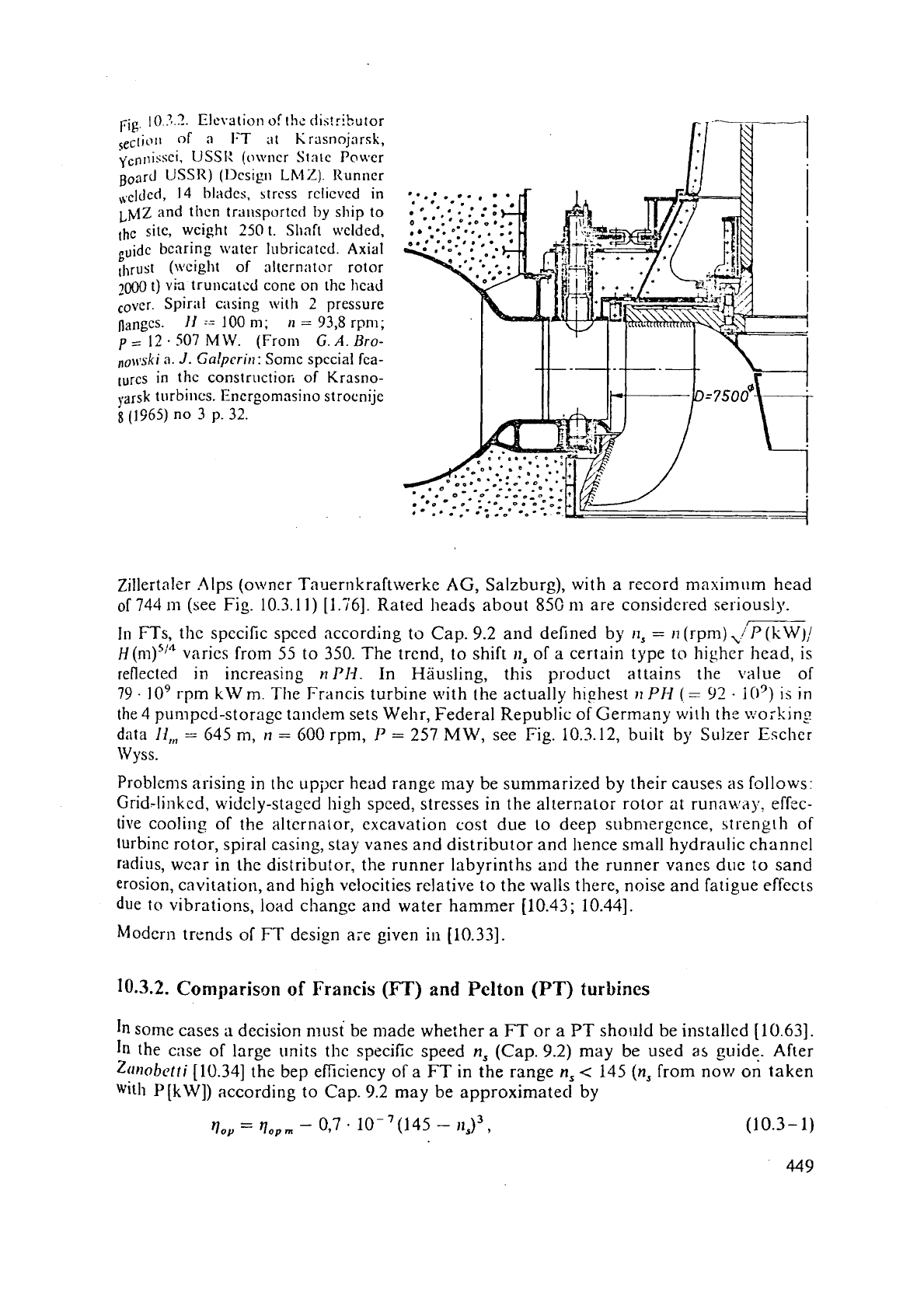
rig.
10
3.9.
Elevation
of
rhc
ciis!rit..utor
Se,-tio~~
of
n
I-T
at
Krasnojnrsk,
\icn~~iss~i,
IISSI:
(owner
State
Power
Board
[JSSR) (I>csig~l
Lh~l%).
Runner
scldcd,
14
bliides,
strcss
rclicvcd
in
~~Z.and
then
transported
by
ship to
,he
s~tc,
weight
250
1.
Shaft welded,
bearing
water
lubricated.
Axial
lllru~t
(\!fcight of altcrn;~tor rotor
7000
1)
vk
truncated cone on the head
,,vcr.
Spiriil casing
with
2
pressure
nangcs.
II
=-=
100
nl;
11
=
93,8
rpni;
p
=
12
-
507
MW.
(From
G.
A.
Bro-
nol\lski
a.
J.
Galpcritl:
Some special fca-
lures
in
the
constructiofi of Krasno-
yarsk
turbines.
Energomasino stroenije
g
(1965)
no
3
p.
32.
Zillertaler .Alps (owner Tauernkraftwerke
AG,
Salzburg), with a record maximum head
of
744
m
(see Fig. 10.3.1
1)
[l.i'6]. Rated heads about
85C
nl are considered seriously.
I11
FTs, thc specific speed according to Cap. 9.2 and defined by
,I,
=
11
(rpm)
./P
(kW)/
H
(n~)~'" varies from
55
to 350. The trend, to shift
11,
of a certain type to higher head, is
reflected in increasing
nP1-i.
In Hiiusling, this product attains the value
of
79.
lo9 rpm kW m. The Francis turbine with the actually highest
11
PH
(
=
02
-
10')
is in
the
4
pumped-storage tandem sets Wehr, Federal Republic of Gerrnany with
the
v:oi-king
data
Ii,,,
=
645 m,
n
=
600 rpm,
P
=
257 MW, see
Fig.
10.3.12, built by Sulzer Esclier
Wyss.
Problems arising in thc upper head range may be summarized by their causes as follows:
Grid-linked, widely-staged
high speed, stresses in the alter~ator rotor at runnv:ajr, effcc-
tive cooling of the
alternator,
excavation cost due to deep submergence, strength of
turbine rotor, spiral casing, stay vanes and distributor and
hence small hydraulic chanrlel
radius, wear in the distributor, the runner labyrinths
and
the runner vanes due
to
sand
erosion, cavitation, and high velocities relative to the walls there, noise and fatigue effects
due to vibrations, load change and water hammer (10.43; 10.441.
htodcrn trends of
FT
design are given in [10.33].
10.3.2.
Comparison
of
Francis
(FT)
and
Pelton
(PT)
turbines
In
some cases
a
decision must be made whether a
FT
or a
PT
sho~~ld be
installed
[10.63].
In the case of large units the specific speed
n,
(Cap. 9.2) may be used
as
guide. Af~r
Z(1tlobctti
[10.34] the bep efficiency of a
FT
in
the range
n,
<
145
(n,
from now on taken
wit11 P[kW]) according to
Cap.
9.2 may be approximated by
-
q,,
-
~,,,,
-
0,7
.
10-'(145
-
II,)~,
(1
0.3
-
1)
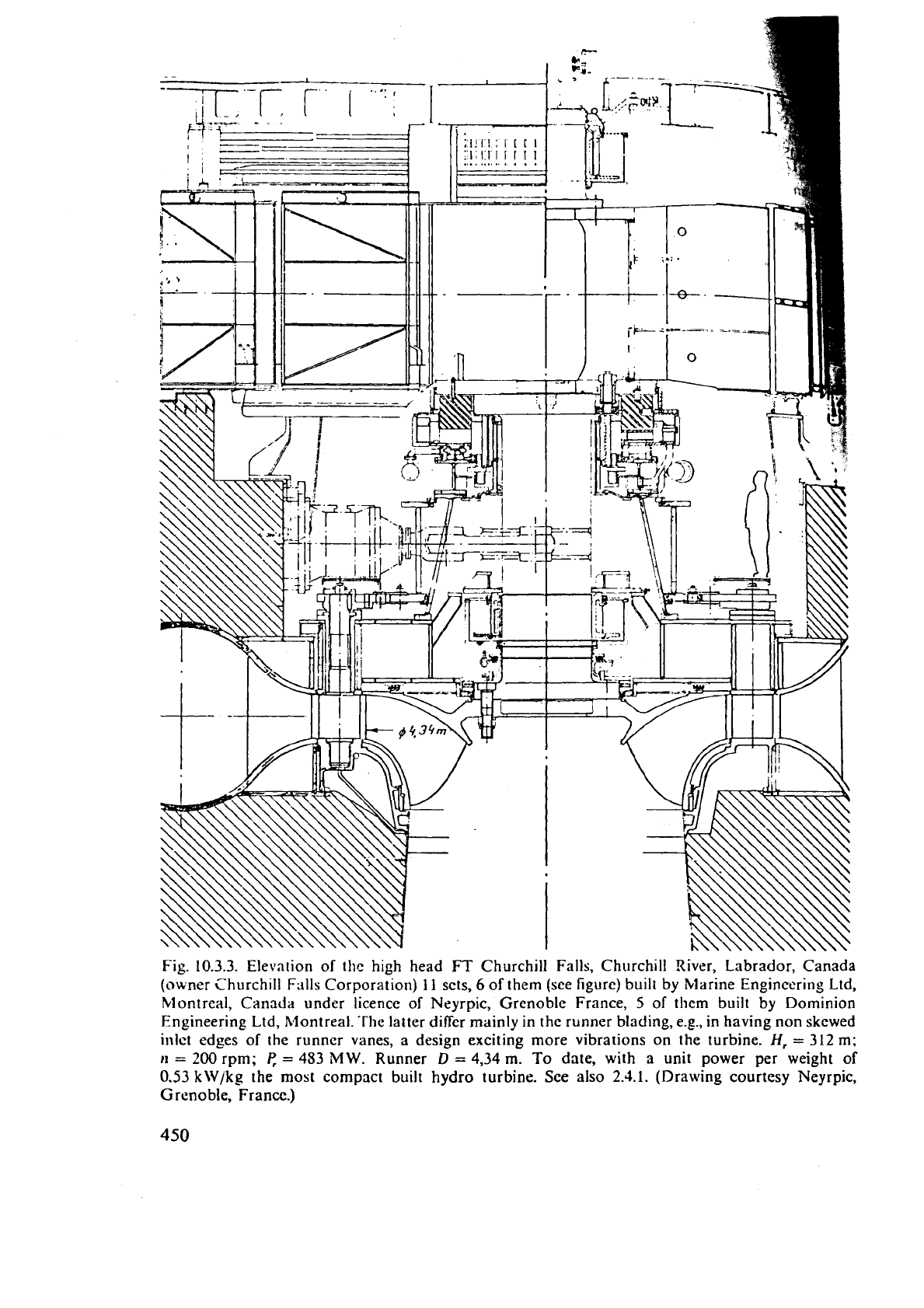
Fig.
10.3.3.
Elevation of thc high head
FT
Churchill Falls, Churchill River, Labrador, Canada
(owner
Churchill Falls Corporation)
11
scts,
6
of them (see figure) built by Marine Engineering Ltd,
Montreal, Canada under licence of Neyrpic,
Grenoble France,
5
of them built by Dominion
Engineering
Ltd,
Montreal. 'rhe latter differ mainly in the runner blading, e.g., in having non skcwed
inlet edges of the runner vanes,
a
design exciting more vibrations on the turbine.
H,
=
312
m;
11
=
200
rpm;
P,
=
453
MW.
Runner
D
=
4,34
m.
To date, with
a
unit power per weight
of
0.53
kW/kg the most compact built hydro turbine. See also
2.4.1.
(Drawing courtesy Neyrpic,
G
renoble, France.)
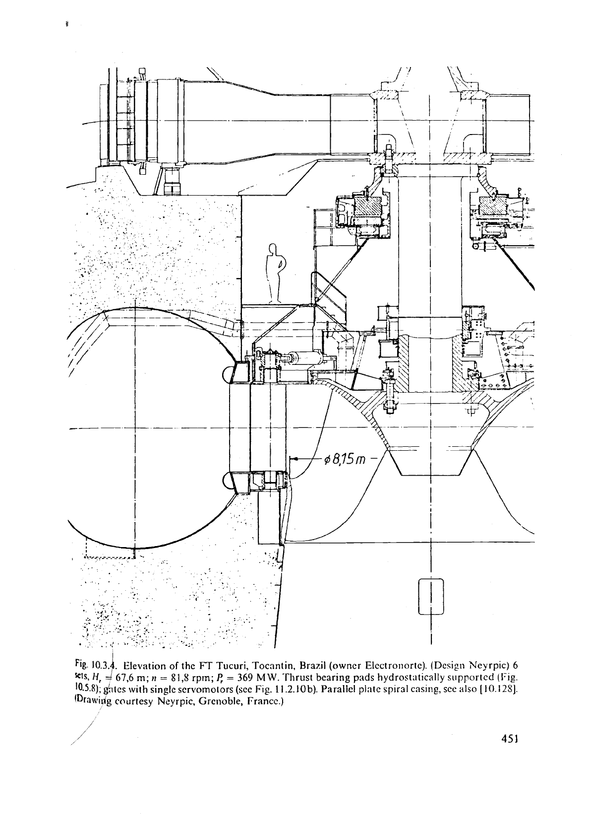
Fig.
10.31
Eleuation of the
FT
Tucuri, Tocantin. Brazil (owner Elccfronortc). (Design Neyrpic)
6
I'
ets,
H,
=
67,6
m;
,I
=
81,s
rpm;
I:
=
369
MW.
-Thrust bearing pads hydrostatically
supported
(Fig.
10-5.8);
&tcs with single ser\lornotors (sce Fig.
11.2.10b).
Parallel
plate
spiral casing, sce also
[10.125].
(Drawidg
courtesy Neyrpic, Grcnoble, France.)
,,.here
rl,,,,,
is thc best attainable eficiency, dcpcnding
011
six
and
the state of thc art (for
,.cry
big
nlacllincs currcntlg
I{,,,,,,,
"11
to 0,95). hftcr tlic Inst rclation llic
I?cp
cfficicnc!.
d
lnrgc
FJ*
\vit!l
11,
=
51
becomes
I!,,,
=
0,s').
hpesiencc sho~i~s that the bcp cBiciency of
a
large I'T ollly just exceeds
I;,,
=
0,9i.
This is mainly caused by ~hc sh:lllow rxtangular
cross section the jet has wllcn leaving the bucket.
gut the problcm exists
if
a
certain
rt,,
fixed by the operating data
H,
Q,
11
of
3
plant can
be
by
a
PT
design. From Cap. 9.2
a
vertical
PT
with
6
jets and the suit:ible
jet
dialneter ratio
do/D
=
111
1,5
atrains
n,
=
49.
On
the other hand from
(10.3.-
1)
a
FT
of
=
0,91
would need
11,
=
77. Obviously
a
gap exists bct~veen the lo\vest possible
~OP
n*
=
77
of a FT and the highest possible
n,
=
49 of a
PT
both having 91
%
be13 efiiciency.
T,
obtain
an
idca how
the
jet diameter ratio
d,/D
influences the
hcp
cificicnc~,
the
fol!o\\
in?
fi_rurzs
by
~~.lnruis
[10.1]
may
scrvc as
guide:
Djd,(rl,,):
6,5(0,82):
7.5(O.S6):
lO(O.89):
20(0.9!.
~hesc
values
:Ire
valid
for
a
nicdium
sized machine
with
only one
nozzle
per nchce!.
\trith
a risins
number
of
jets,
the
efficiency drops at the same jet diameter ratio.
~ccordillg to Sulzer Escher VJyss an overlap exists between
FT
and
PT
in the
H
(Q)
plane
(Fig.
10.3.16).
'This has
sn
upper limit at
H
=
750 m and
a
lower limit described by:
In
11
(nl)
=
4,l
+
0,54
In
Q
(rn3/s);
H
and
Q
rated figures.
11
may be mentioned that the cross flow turbine originated by Michell and Tjanki, nou1
actually ]made by the West German firm Ossberger (see Figs. 3.4.5; 3.4.9; 3.4.10) may
overlap this gap
at
the lower head and flow range. Below the above limits the
FT
rules
out the P7'
by
the lowcr cost
of
its set or by lower operating cost.
Reasons: For
a
certain head the bucket speed coefficient of a PT being
Klr
=
0,42..
.0,52
is
below that
of
a
FT
wit11
Klr
=
0,7..
.
1,l (upper limit for loiver head). bloreove: the unit
discharge
Q,,
(Cap. 9.2) of
a
PT is much smaller than that of
a
FT.
For a certain head
and
output this leads to
an
increase of speed by 30 to 50% of
a
FT
over
:I
PT. Hence
torque and size of set of a FT is smaller than that of
a
PT.
Accordiilgly also the distance
of adjacel~t sets and the power house required becomes smaller for a
FT
than for
a
PT.
On
the other hand
a
FT
may require more expenditure than a
PT
due to its submergence.
This argument in favour of a PT may disappear in the case of an underground station.
For low heads and large wheel diameters the head loss due to the free height above the
tail water level may favour
a
FT,
where the free height
is
used in the diffuser. The
PT
must
have this free height to avoid disc friction and excessive windage loss (Cap.
5.5).
Further reasons affecting the decision between
PT
and
FT,
see also [10.63]:
a)
In
high head plants with strongly erosive sandy water (with quartz sand) the conse-
quences of excessive
wear,
e.g.,
in the labyrinths of a
FT
may
be worse than those in the
nozzle and
oil the needle of a
PT,
since the first enlarges considerably the clearance
of
the
labyrinth gaps and hence the leakage loss especially in high head
FTs with their rather
small ruilner breadth to tiianicter ratio
b/D
(Figs. 10.3.9;
10;
12),
a loss which does not
exist in
a
PT.
6)
The
FT
has a more pronounced efficiency peak vs load
P
at bep than a
PT
and hence
&more suitable for constant base load demand. Contrary to this the
PT
has the flattest
tficienc) vs load curve. Thereby
a
PT
may be preferred if tile plant frequently has to
Su~ply v rying peak load and hence often operates in the part load range.
b
For
exahple the supply of traction power in West Germany, Switzerland and Austria,
which h~vc a special grid with
163
Hz
for this purpose, is often effected by
PT
sets.
The
harts
needing
frequent repair and replacelnent in
a
FT
opcrated by highly erosive
"nd$ater are
[he
labyrillth rings, the guidz vanes, the wear rings of the distributor and
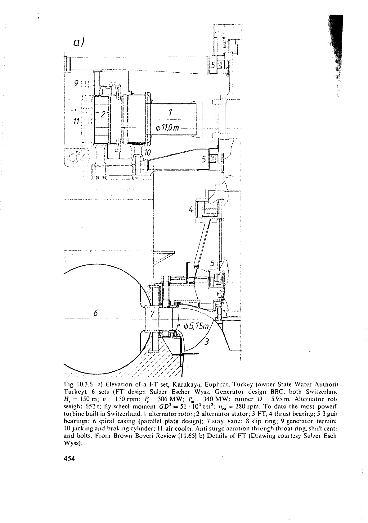
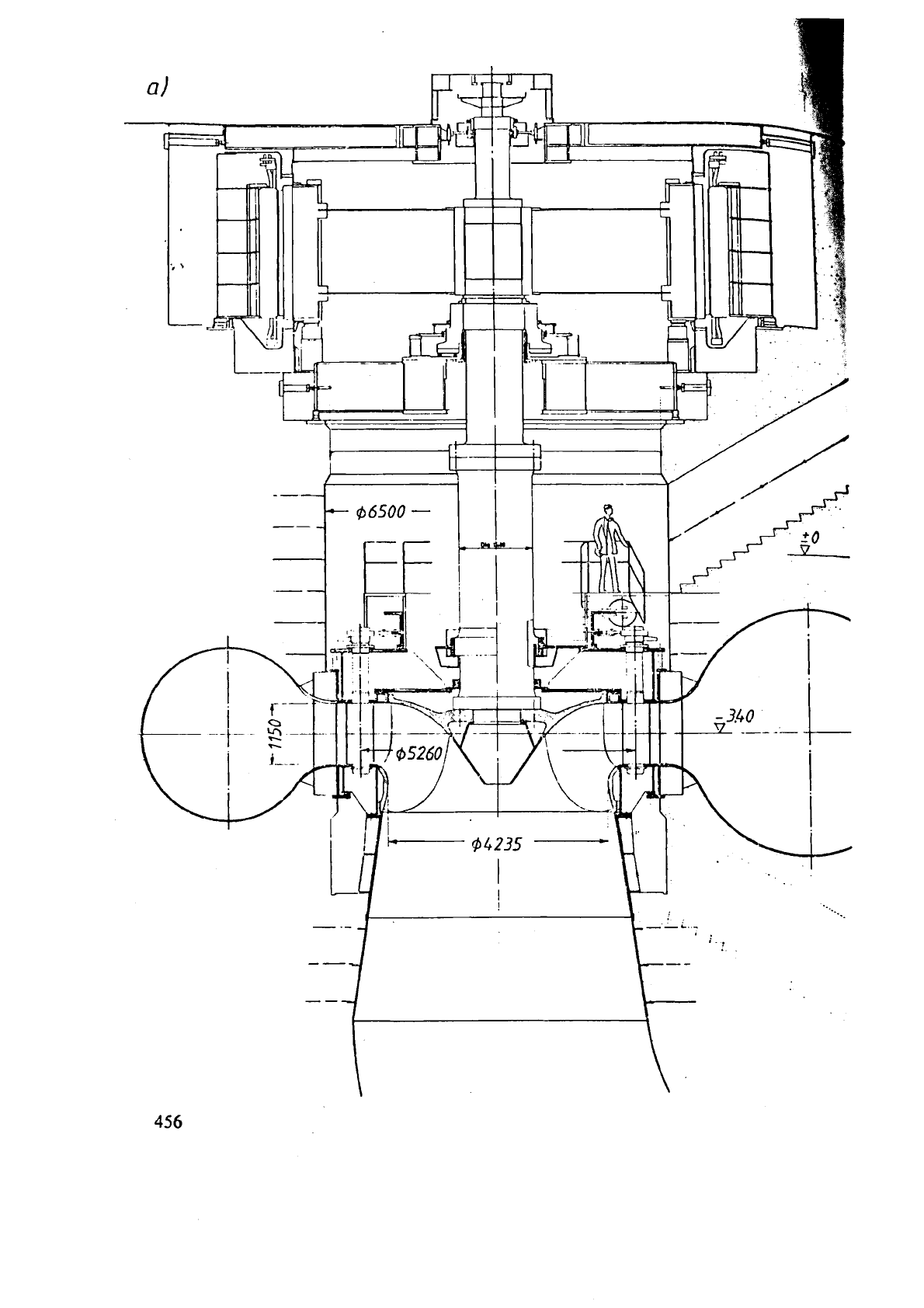
Fig. 10.3.6.
a)
Elevation of
n
FT
set, Karaknyi~. Euphrat, Turkey (owner State Wstcr Authori~
Turkey). 6 sots
(FT
design Sulzer Eschcr Wys..
Generator
&sign
BRC.
both S\\itzerlanc
H,
=
150111;
rr
-
lS0rprn;
5
=
336MW;
P,
=
340
h1W:
runner
D
=
595
m.
All.-
LI
liator rot(
weisht
652
!:
fly-wheel rno~ncnt
GD~
=
51
-
10'
tm2;
?I,,,
=
290
rpnl. To date the most powcrf
turbine
bbilt
in
S\vitzerland.
1
alternator rotor;
2
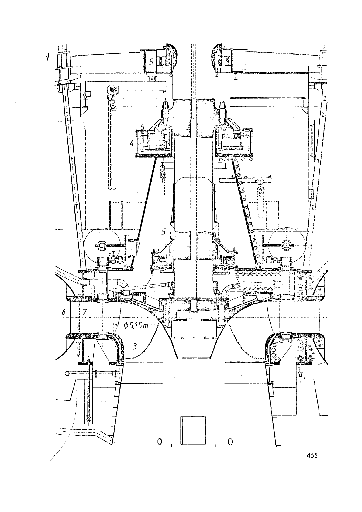
alternator st:\tor;
3
FT;
4 t!irusl bearing;
5
3
guic
beariiigs;
6
hpiral casing (parallel
plate
design);
7
stay vane;
S
blip ring;
9
generator
termini
10 jacking and braking cylinder;
11
air coolcr.
Anti
surge ncration thr'ugh throat ring. shaft cent1
and bolts. From Brown
Boveri
Review
[I
:.65]
b) Dct;lils
of
FT (Dr'~*ing courtesy Sulzer Esch
Wyss).
