Raabe J. Hydro power - the design, use, and function of hydromechanical, hydraulic, and electrical еquipment
Подождите немного. Документ загружается.

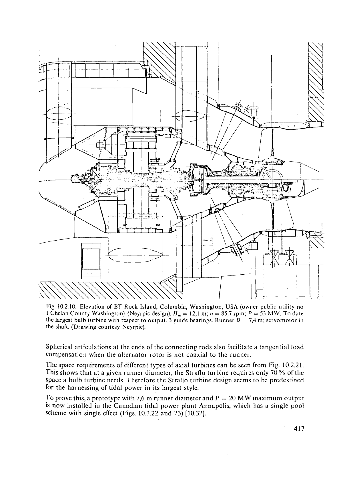
Fig.
10.2.10.
Elevation of
BT
Rock Island, Columbia, Washington,
USA
(owner public utility
no
1
Chelan County Washington). (Neyrpic design).
19,
=
12,l
m;
n
=
85,7
rpm;
P
=
53
MU'.
To date
the
largcst bulb turbine with rcspect to output.
3
guide bearings. Runner
D
=
7,4
m;
servomotor
in
the shaft. (Drawing courtesy Neyrpic).
Spherical articulations at the ends of the connecting rods also facilitate a tangential load
compensation when the
alternator
rotor is not coaxial to the runner.
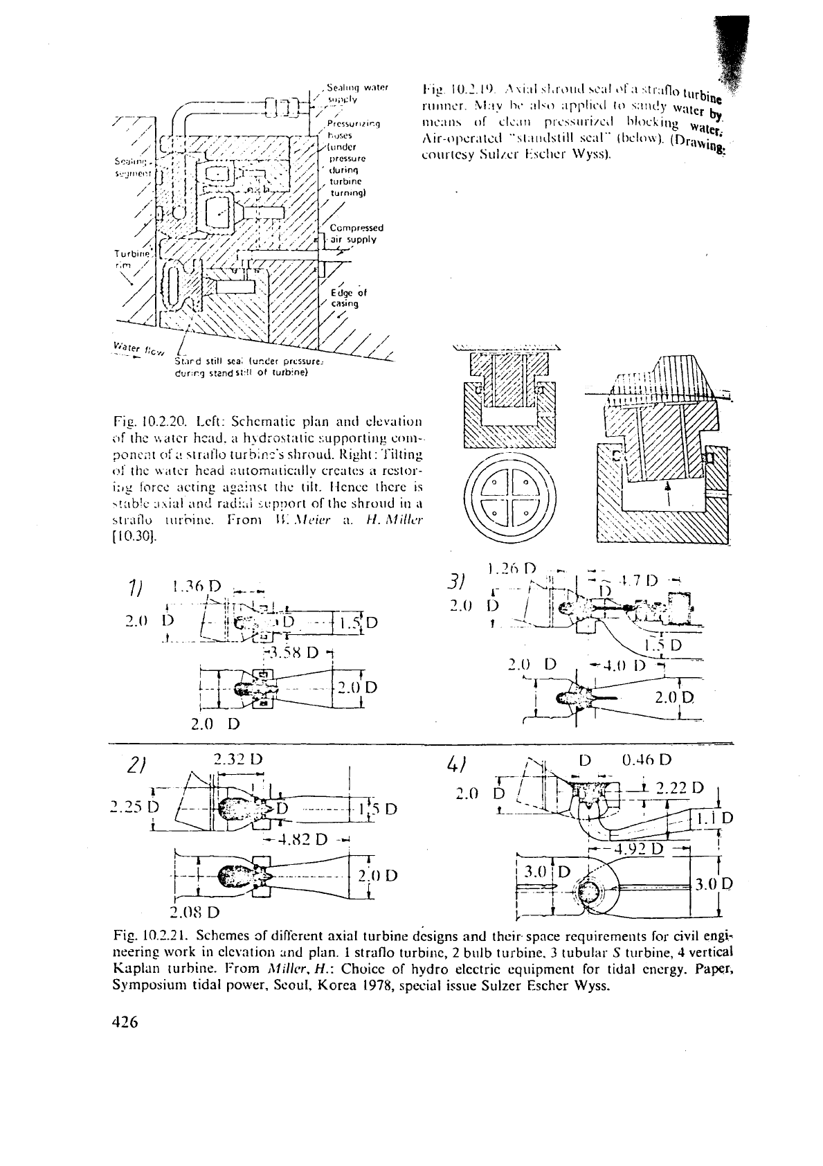
The space requirements of different types of axial turbines call be secn from Fig. 10.2.21.
This shows that at a given runner diameter, the Straflo turbine
requircs only
70%
of the
space a bulb turbine needs. Therefore the
Stratlo turbine design seems to be predestined
for the harnessing of tidal power in its largest style.
To prove this,
a
prototype with
7,6
m
runner diameter and
P
=
20
MW
rnaximum output
is now installed in the Canadian tidal power plant Annapolis, which
has
a
single pool
scheme with single effect (Figs. 10.2.22 and 23) [10.32].
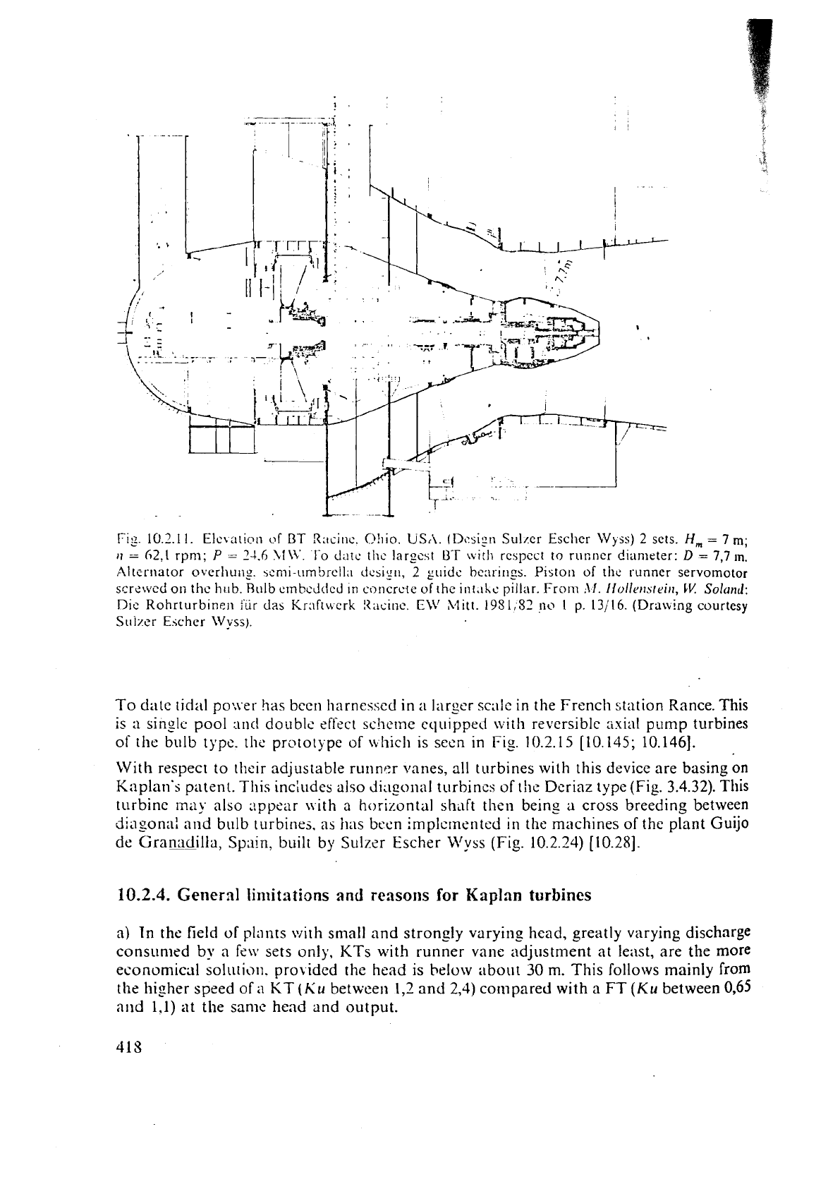
Fig.
10.2.1
1.
Elevation
~rf
BT
Racinc.
C?!~io. US,\. (Desi;!i Suller Escher
Wyss)
2
sets.
H,
=
7
m;
11
=
h2,l
rpm;
P
-
24.6
\l\V.
1.0
date
thc
largcst
UT
\vi:Ii
rcspcct
to
runner diameter:
D
=
7,7
In.
Altertlator overhut~p. semi-iimbrcll;~ dcsigrl,
2
guidc bc::rir~gs. Piston of the runner servomotor
screwed on
thc
h~tb. Rulb
crnbcJ(lcJ
In coricrcte
of
the
int.ihc pillar. From
:\I.
l~ollerntt.in,
I.1!
Soland:
Dic
Rohrturbinei~
i'iir
das Krnftwcrk
!<acinc.
Cii'
Mitt.
19S1;52
no
1
p.
13i16.
(Draning courtesy
Siiizzr Escher IVyss).
To date tidal po:vel-
has
been harnessed in
a
larger scale in the French station Rance. This
is
rl
sinzlc pool
:an(!
doublc
effect
scheme equipped with reversible lixirll pump turbines
of the bulb type.
the prototype
of
\.chic11 is seen in
Fig.
10.2.15
[10.145;
10.1461.
With respect to their adjustable runner vanes, all turbines with this device are basing on
Kaplan's patent. This includes also dirlgol~al turbines
of
the
Deriaz typc (Fig.
3.4.32).
This
turbine
may
also Lippear nith
a
horizontal shaft then beins a cross breeding between
dii~sonal
and bulb turbines, as
has
been implc~nented in the machines
of
the
plant Guijo
de
Granridilla,
Spain,
built by Sulzzr Escher illyss (Fig.
10.2.24) [10.28].
10.2.4.
General
li~llitntions
and
reasons
for
Kaplan
turbines
a)
In
the field
of
plants with small and stronsly varying head, greatly varying discharge
consumed
by
a few sets only, KTs with runner vane adjustment at leilst, are the more
economical solution. provided the head is
below
about
30
m.
This follows mainly from
the
higher speed of
a
KT
(Ku
between
1,2
and
2,4)
compared with a FT
(Ku
between
0,65
and
1.1)
at
the same head and output.
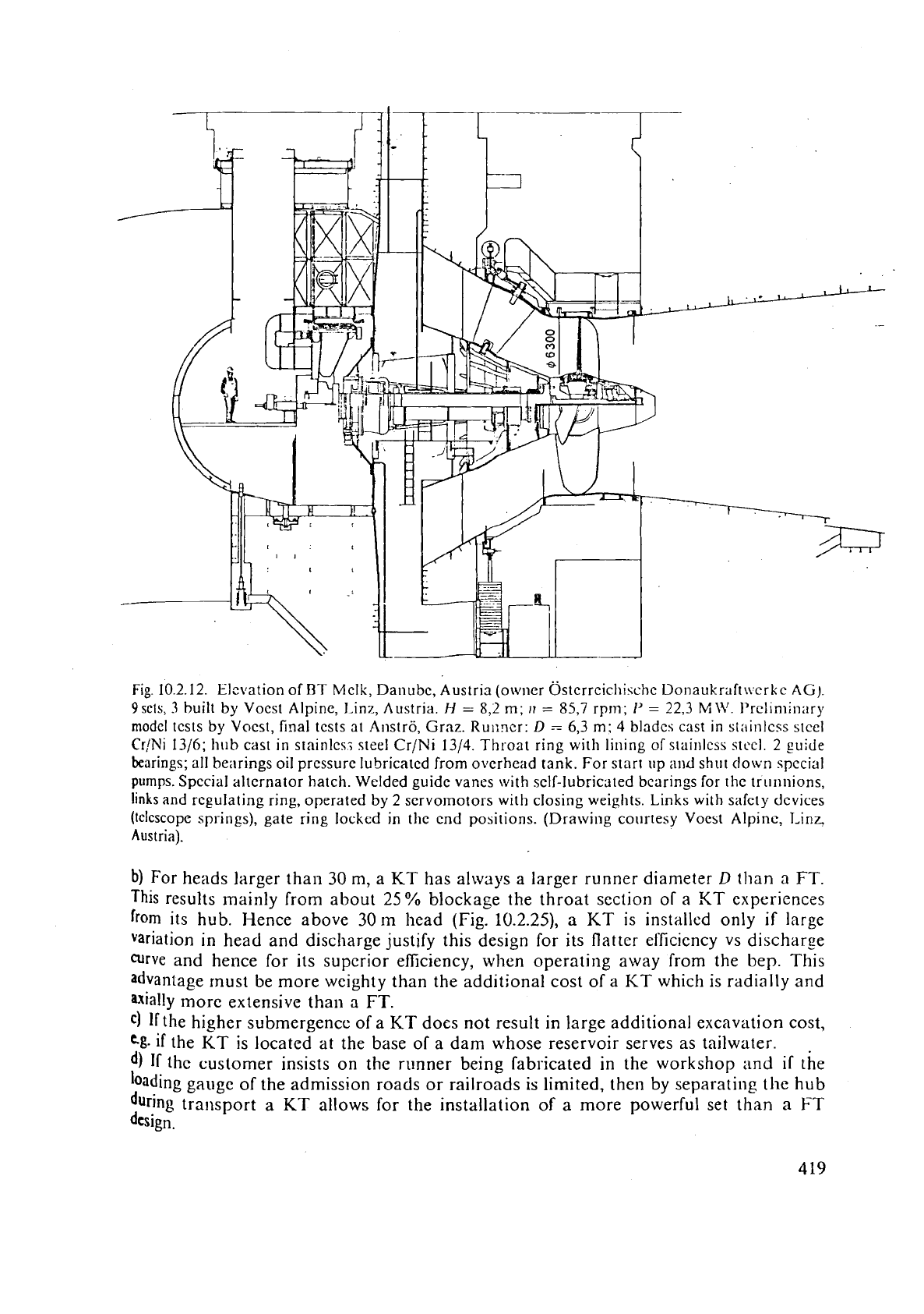
Fig. 10.2.12. Elevation of
J3T
Mclk, Danubc, Austria (owner ~stcrrcichischc Donaukraft\\.crkc
AG).
9scts,
3
built by Vocst Alpine, l.inz, Austria.
H
=
8,2
m;
11
=
85,7
rprn;
1'
=
22,3
Mi+'.
Prcliniinary
model
tcsts
by
Vocst, final tcsts
at
Anstro, Grnz. Ru~:ncr:
D
-
6,3
m;
4
bladcs cast in sininlcss stcel
Cr/Ni
1316;
hub
cast in stainles-; steel Cr/Ni
1314.
Throat ring with lining of slainlcss stcel. 2 guide
bearings;
all be:~rings oil pressure lubricated from o~erhci~d tank. For start
up
and
shut clown special
pumps.
Spccial alternator hatch. Welded guidc vanes with sclf-lubricated bcarings for the tri~nnions,
links and
regulating
ring, operated
by
2
servolnotors with closing weights. Links with safety devices
(telescope
springs), gate ring locked in the end positions. (Drawing courtesy Voest Alpine, 1,inc
Austria).
b)
For heads larger than
30
m, a KT has always a larger runner diameter
D
than
a
FT.
This results mainly from about 25
%
blockage the throat section of a
KT
experiences
from
its hub. Hence above
30
m
head (Fig. 10.2.25),
a
KT
is installed only if large
variation in head and discharge justify this design for its flatter
eficicncy vs discharge
curve
and hence for its supcrior efficiency, when operating away from the
bep.
This
advantage
rnust be more wcighty than the additional cost of a KT which is radially and
axially rnorc extensive than
a
FT.
C)
If
the higher submergence of a KT does not result in large additional excavation cost,
Cg.
if
the
KT
is located at the base of a dam whose reservoir serves as tailwater.
d)
If
thc customer insists on the runner being fabricated in the workshop and if the
hading gauge of the admission roads or railroads is limited, thcn by separating the hub
during
transport a
KT
allows for the installation
of
a more powerful set than
a
FT
design.
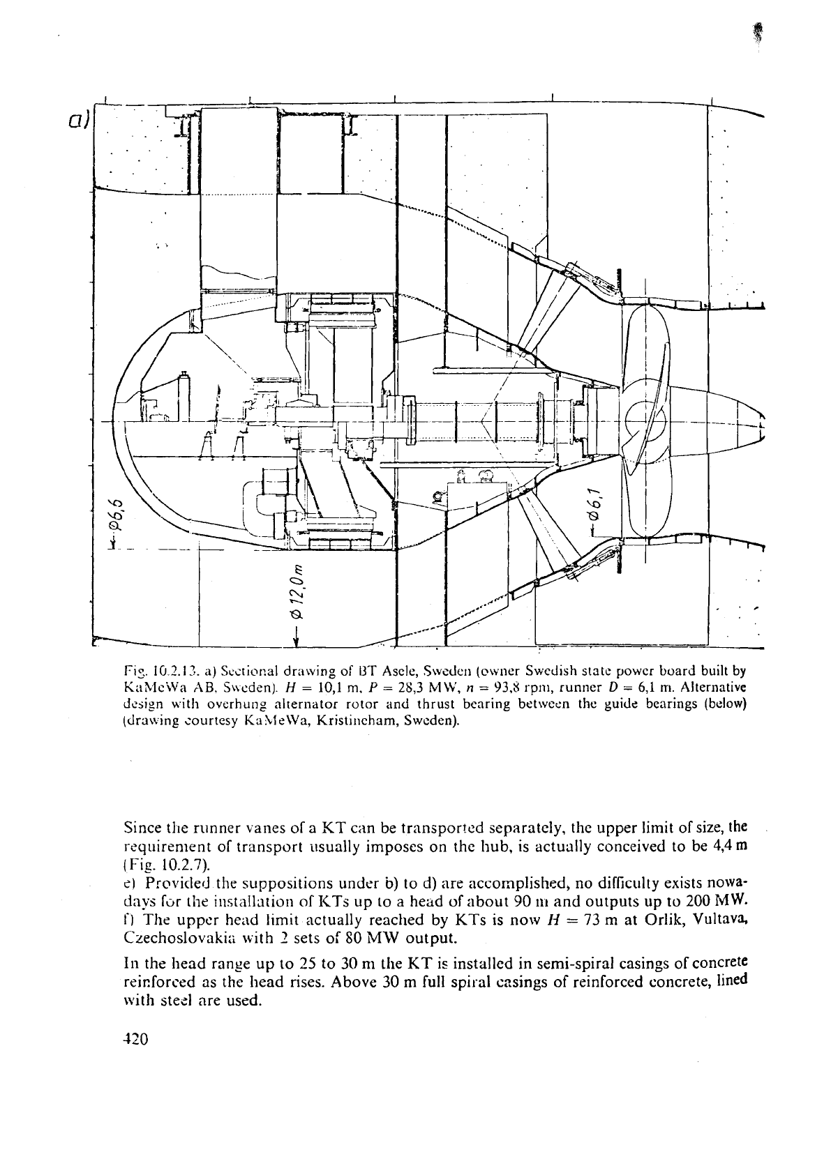
FIS.
IO
3.17.
a)
S~iti~~?al
drawing of
UT
Asele,
Swede11
(owner Swedlsh state power board built
by
KaMciVa
XB,
S~cden)
H
=
10,l
m,
P
=
28,3
MLV,
n
=
93.8
r-pnl, runner
D
=
6,l
rn.
Alternative
design
with overhuilg alternator rotor
and
thrust bearing betwecn the guide bearings
(below)
(draning courtesy S;Yhl&a, kistincham,
Sweden).
Since tile runner
vanes
of a
KT
cartbe transpor!ed separately, the upper limit of size, the
requirement
of
transport usually imposes on the hub, is actually conceived to be
4,4
m
(
Fig.
10.2.7).
eI
Provicled
the
suppositions under
b)
to d) are accomplished, no difficulty exists nowa-
days
f"r
[he
installation
01
I<Ts
up
to
a
head
of
about
90
ti1
and outputs up
to
200
MW.
f)
The
upper head limit actually reached by KTs
is
now
111
=
73 m at Orlik, Vultava,
Czechoslovakia ~vith
2
sets
of
SO
MW
output.
In
the head range up to
25
to
30
m
the
KT
i,c
installed in semi-spiral casings
of
concrete
rcicforced as
the
head rises. Above 30
m
full spiral casings
of
reinforced concrete, lined
with stecl are used.
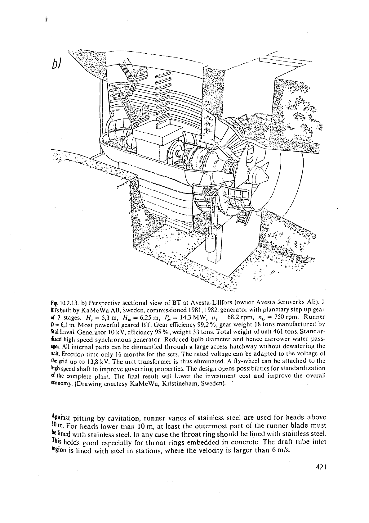
Fig.
10.2.13. b) Perspective sectional view of BT at Avesta-1,illfors (owner Avesta Jernverks AD).
2
ITS
built by KaMeWa AB, Sweden, commissioned 1981, 1952. gcr~erator with planetary step up gear
d
2
stages.
H,
=
5,3 m,
H,
=
6,25
m,
P,
=
14,3
blW,
11,
=
65,2
rpm,
,I,
=
750
rpm. Runner
D
=
6,1
m.
Most powerful geared BT. Gear efficiency
99,2%,
gear weight
I8
tons manufactured
by
kal
Lrtval. Generator
10
kV,
efficiency 98
%,
weight 33 tons. Total weight of unit 461 tons. Standar-
dizcd
high speed synchronous generator. Reduced bulb diameter and herice narrower water pass-
&@.
All internal parts can be dismantled through a large access hatchway without dewatering the
'nil.
Erection time only 16 months for the sets. The rated voltage can be adapted
to
the voltage of
grid up
to
13,s
kV.
The unit transformer is thus eliminated. A fly-whcel can be attached to the
high
speed shaft to improve governing properties. The design opens possibilities for standardization
d
lhe
co~nplete plant. The final result will lcwer the investment cost and improve the overall
-nomy.
(Drawing cotirtesy KaMeWa, Kristineham, Sweden).
.
pitting by cavitation, runner vanes of stainless steel are used for heads above
I0ln.
For heads lower than
10
m,
at least the outermost part of the runner blade
must
hlined
with stainless steel. In any case the throat ring should be
lined
with stainless steel.
his
holds good especially for throat rings embedded in concrete. The draft
tube
iniet
%on
is lined with steel in stations, where the velocity is larger than
6
m/s.
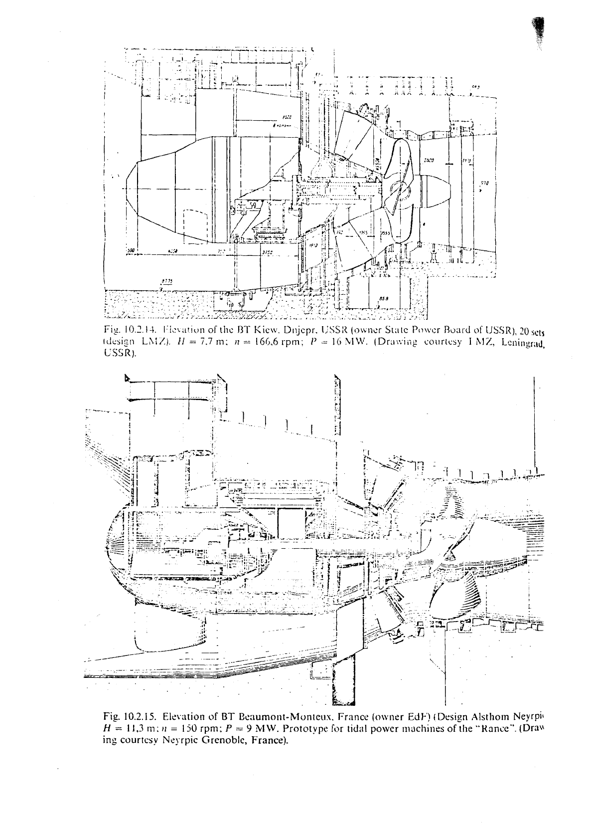
Fig.
10.1.14.
I:i<\ii!ic)tl
of
tllc
IIT
Kiciv.
D~ijcpr.
IJSSIl
(owner
State
Po\vcr
Rod
of
USSR),
20
SC(s
ldusi~n
LSiZi.
El
=
7.7
111:
11
--
166.6
rpm;
I'
=
16
CIMi.
(Dra\:.iii$
courtesy
I
hl%,
1-cningr;,d,
CSSR).
Fig.
10.2.15.
Elevation
of
BT
Eeaumont-Monteus. France (owner
EdE')
(Design Alsthom Neyrpii
H
=
1
1,3
m:
rl
=
150
rpm:
P
=.
9
31
W.
Prototype
for
tidal
power
nlachioes
of
!he "Kancke". (Dm
ing courtesy Nzyrpic Grenoblc,
France).
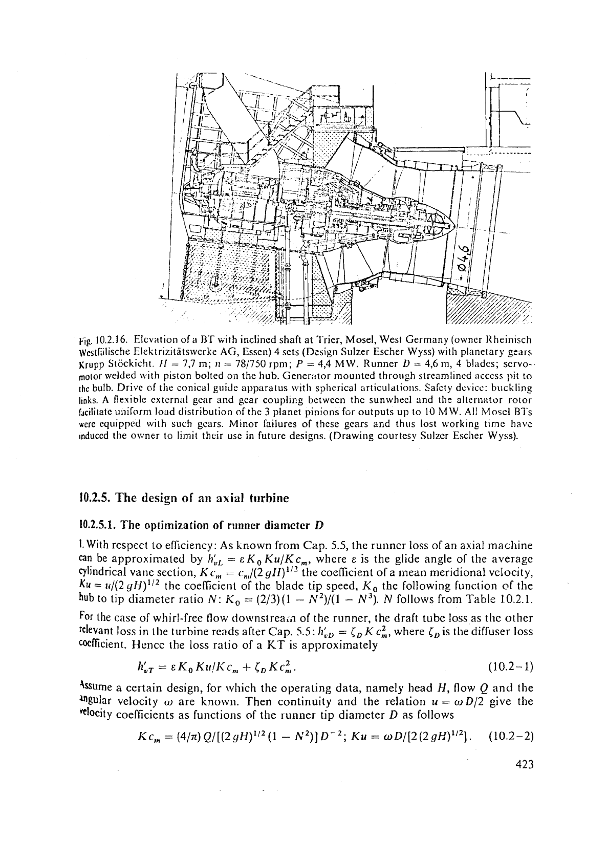
Fig.
10.2.16. Elevation of
a
B'T
with inclined shaft
ar
Trier, Mosel, West Germany (owner Ilheinisch
\~estfilische Elektrizitatswcrke
AG,
Essen)
4
sets (Design Sulzer Escher Wyss) with planetary gears
Krupp
Stockicht.
ti
=
7,7
m;
II
=
781750
rpm;
P
=
4,4
MW.
Runner
D
=
4,6
In,
3
bl;ldcs; servo-
motor welded
nith piston bolted on the hub. Generator rnountcd through streamlined ;iccess pit to
the
bulb. Drive
of
the conical guide apparalus wit11 spherical :trticuldtions. Safety dc~lcc: bucklinc~
links.
A
flexible cxtcrn;il gear and gear coupling between the sunwhecl and the alternator rotor
f~cilitate uniform load distribution
of
the
3
planet pinions f~r outputs up to
10
MW.
A11
Mosel BTs
scre equipped with such gears. Minor failures of these gears and thus lost working time havz
~nduccd the owner to limit their use
in
future designs. (Drawing courtesy Sulzer Escher Wyss).
10.2.5.
The
design
of
ail
axial
turbine
10.2.5.1.
The
optimization of
runner
diameter
D
I.
With respect to efficiency: As known from
Cap.
5.5,
the runner loss of an axial machine
can
be approximated
by
h:,
=
r:
KO
Ku/K
c,, where
E
is the glide angle of the average
cylindrical vane section,
Kc,,
=
c,,/(2
g~)"Qhe coeficient of a mean meridional velocity.
Ku
=
lrl(2
g~)''2
the coefficient or the blade tip speed,
KO
the following function of the
hub
to
tip diameter ratio
N:
KO
=
(2/3)(1
-
N2)/(1
-
N3).
N
follows from Table
J0.2.1.
For
the case of whirl-free flow downstrea;,l of the runner, the draft tube loss as the other
relevant loss in the turbine reads after Cap.
5.5:
IT:,
=
(,
K
ci, where [,is the diffuser loss
mfficient. Hencc the loss ratio of
a
KT
is approximately
h;,
=
E
KO
Klr!l< c,,
+
(,,
Kc:,.
(10.2-
1)
kme
a
certain design, for which the operating data, namely head
H,
flow
Q
and
the
%ular velocity
w
are known. Then continuity and the relation
u
=
o
D/2
give the
docity coefficients as functions
of
the runner tip diameter
D
as follows
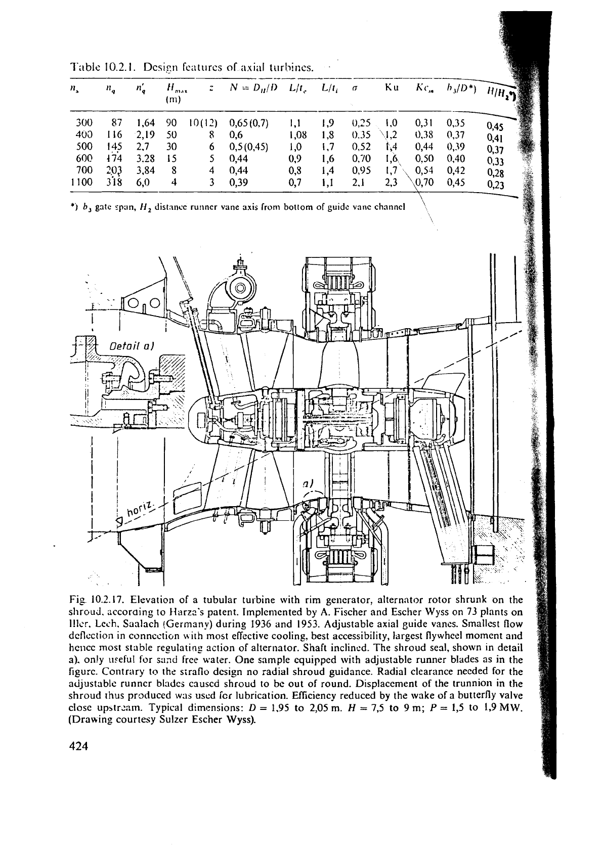
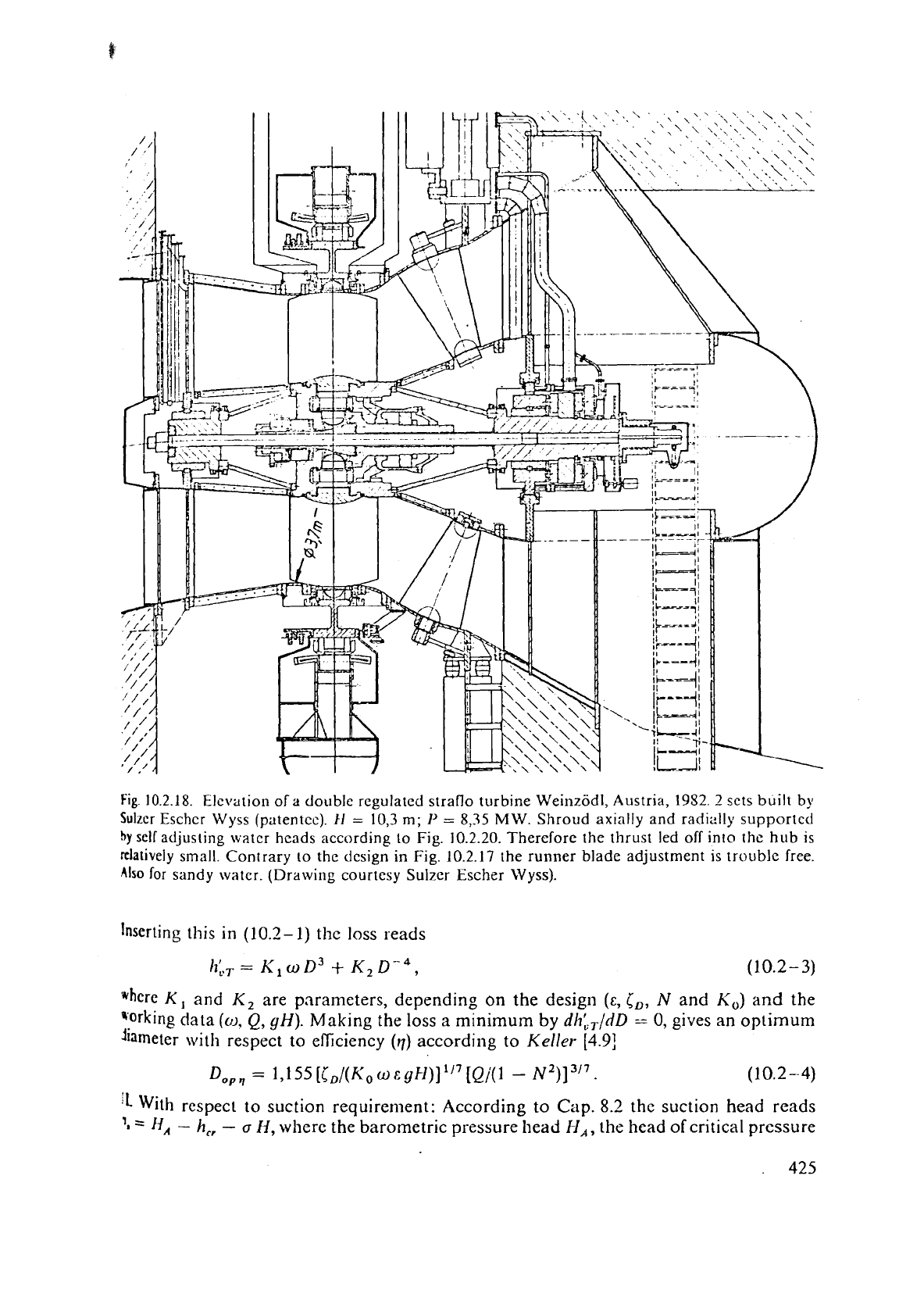
Fig.
10.2.18.
Elevation
of
a
double regulated straflo turbine Weinzodl, Austria,
1952.
2
sets built
by
Sultcr Eschcr Wyss (patentee).
11
=
10,3
m;
1'
=
8,35
MW.
Shroud axially and radially supported
by
self
adjusling water hcads according
to
Fig. 10.2.20. Therefore the thrust led off into the
hub
is
rtlatively small. Contrary to the dcsign in
Fig.
10.2.17 the runner blade adjustment is trouble free.
Also
for sandy watcr. (Drawing courtesy Sulzer
Escher
Wyss).
Inserting this in
(10.2-
1) thc loss reads
"here
K,
and
K2
are parameters, depending on the design
(E,
i,,
N
and
KO)
and
the
"orking data
(o,
Q,
yH).
Making the loss
a
minimum
by
dh:,,/dD
=
0,
gives an optimum
diameter with respect to elliciency
(4)
according to
Keller
[4.9]
1L
With respect to suction requirement: According to
Cap.
8.2
the suction head reads
'1
=
l-I,
-
h,,
-
a
H,
where the barometric pressure head
I-I,,
the
head
of critical pressure
,
Se.d~nq
wAter
1.1g.
10.2.
It).
;j\i:~i
S\,I.OII~
>c;I~
t\f;l
:Ltr;lfl(,
~-~tnncr. hI:tv
17,-
;II<O
;tppl~t-~l to s:t~ic!y
\v:,lcr
IIIC;III>
of
c1c.111 ~~-~~ss~tri/c,I I~lt>cLi11~
Water;
,\ir-opcr.~tcd
"~I;III~s~I!~
SC:I~.. (~cI~)Iv). (Drzt,,,in
c0111-1esy Sullcr Escltcr
\Vyss).
fk
turning)
Turblrle,
Edge
bf
-
.-
St.lrd
still
sea,
luzder
pressure:
dvr;rg
stand
st,!l
of
turb:ne)
Fig.
10.2.20. I-eft: Schematic
pian
ant1
clevatio~i
i-~f
th~ uatcr hcad.
a
h~.diosr;ltic :;upporting co111--
?c?nc.;?r
of;!
stritilo turbinc's shri>ucf. Kight: .filling
(-1:
thc
LI.;I~C'I
head
;:utomatic;~lly crcatcs rcstor-
i;rg
forcc
acting ;tgi:11ist tllc lilt. I-Ience there
is
\t;tb!t.
:~iial
ant!
ruc!i:ii
iup~~ort of thc shroud
it]
i\
s[r;~ilu
ttlrbitie. Fron~
\!i
.\lc>ii!r
a.
ti.
Afi/l~~r
[
1@.3G].
I.'hD
-.-.
--
I)
1.36
D
---
.
...
J.LiL'
;:
T74.?J.-.-
I.
(
1
I,
-
i!
c:::.,
m2i~
i
.
t
. .
.
-
-LA--
L?
KJ-
,
-3.58
D
-i
2.0
D
.
.---
2.32
1>
0.46
D
I
-4.32
D
-y
D
2.08
D
Fig.
10.2.21.
Scl~emes
3f
dikrent
axial
turbine designs
and
their. space requirements for civil engi-.
noering work in
elevation
and
plan.
1
straflo turbine,
2
bulb turbine,
3
tubular
S
turbine,
4
vertical
Kaplan
turbine.
From
~lli'llcr,
H.:
Choicc
of
hydro elcctric cquipmcnt for tidal encrgy.
Papar;
Symposiunt tidal power, Scoul, Korea
1978,
special
issue
Sulzer Eschcr Wyss.
426
