Raabe J. Hydro power - the design, use, and function of hydromechanical, hydraulic, and electrical еquipment
Подождите немного. Документ загружается.

~i~.
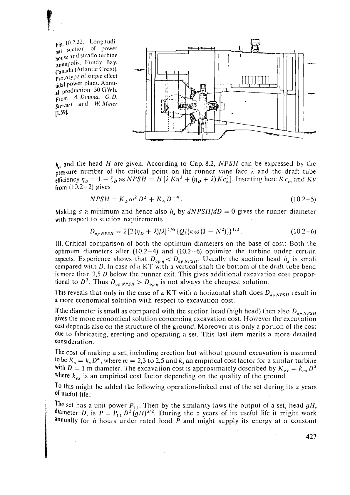
10.2.22
Longitudi-
nal
section
of power
hous~
311d
strnflo
~LII
bine
,,,,,l;lpolic, I-.untl
y
Hay,
C3n3Ja
(.At
l:111t
ic
Coast).
prototype
of
sirlglc
effect
power
1.dant.
Annu-
al
50
G\Vh.
From
A.
DOUJPIU,
G.
n.
srr\%lurt
"ld
dV
11leier
11.591.
h,
and the head
I1
are given. According to Cap.
8.2,
NPSH
cnn be expressed by the
pressure number of the critical point on the runner
vane face
1
and the draft tube
clficie~lcy
=
1
-
CD
as
NI'SN
=
I11
[i.
Klr2
+
(ilD
+
1,) Kc:,].
Inserting here
Kc,,,
and
KII
froln
(1
0.2
-
2)
gives
lak king
a
a.
minimum and hence also
h,
by
dhTPSN/dD
=
0
gives the runner diameter
with respect to suction
requirements
111. Critical comparison of both the optimum diameters on the base of cost: Both the
optimum
diametcrs after
(10.2-4)
and
(10.2--6)
optimize the turbine under certain
aspects. Experience shows
that
Do,.,
<
Do,,,,,,.
Usually the suction head 11,
is
small
compared
with
L).
In case of
;i
KT
;h.lth
a
vertical shaft the bottom
of
the
dr;l!'t
tube bend
is
more than
2,5
D
beloiv t!le runner exit. This gives additional exca\ration cost propor-
tional to
L)"
Thus
D,,,,,,,,
>
Do,,
is not always the cheapest solution.
This reveals that only in the case of a
KT
with
a
horizontal shaft does
Do,
N,,I,
result in
a
more economical solution with respect to excavation cost.
Ifthe diameter is small as comp;ired with the suction head (high head) then also
Do,v,,r,H
gives the more economical solution concer~~ing excavation cost. JJoi~ever the excr:vatlon
cost depends also on the structure of the ground. Moreover it is only a portion
of
the cost
due to fabricating, erecting and operaling
n
set. This last item merits a more detailed
considera tion.
The cost of making a set, including erection but without ground excavation is assumed
lo
be
K,
=
k,
Dn',
where
rn
=
2,3
to
2,5
and
k,
an
empirical
cost factor for a si~nilar turbine
with
D
=
1
m
diameter. The excavation cost
is
approximately described by
K,,
=
k,,
.?I3
where
k,,
is an empirical cost factor depending on the quality of the ground.
To
this might
be
addcd tLc following operation-linked cost of thc set during its
z
years
of useful life:
fie
set has
a
unit power
P,,.
Then
by
the
similarity Inws the output of a set, head
gH,
diameter
D,
is
P
=
PI,
D?
(O~)312.
During the
z
years of its useful life
it
might work
annually for
h
hours under rated load
P
and might suppiy its energy at
a
constant
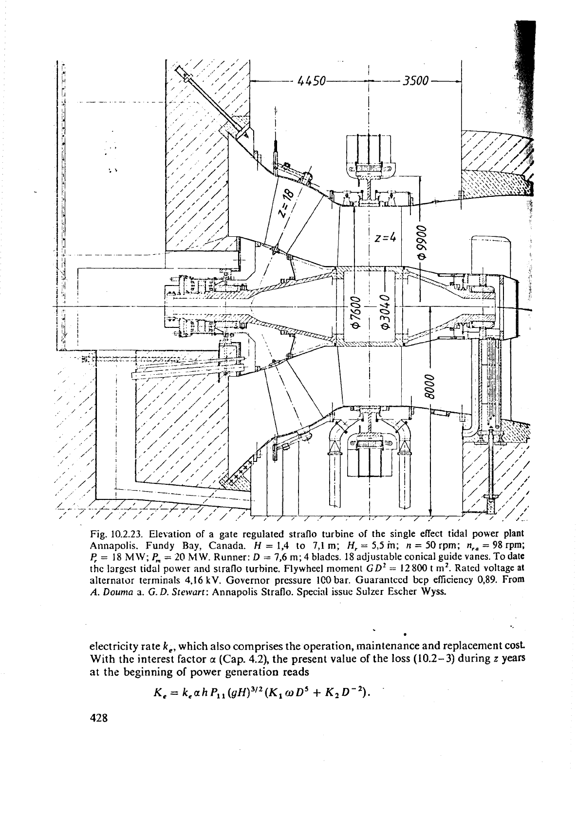
Fig.
10.2.23.
Elevation of a gate regulated straflo tsrbine
of
the single effect tidal power plant
Annapolis. Fundy Bay, Canada.
H
=
1,4
to
7,1
m;
H,
=
5,5
in;
n
=
50
rpm;
n,,
=
98 rpm;
I:
=
18
MW;
P,
=
20
MW.
Runner:
D
=
7,6
m;
4
blades.
18
adjustable conical guide vanes. To date
the largest tidal power and straflo turbine. Flywheel moment
GDZ
=
12800
t
m2.
Rated voltage at
alternator terminals
4.16
kV.
Governor pressure 100 bar.
Guaranteed
bep efiiciency 0,89. From
A.
Doun~a
3.
G.
D.
Ste~vurf:
Annapolis Straflo. Special issue Sulzer Escher
Wyss.
electricity rate
k,,
which also comprises the operation, maintenance and replacement
cost.
With
the
interest factor
a
(Cap.
4.2),
the
present value of the loss
(10.2-
3)
during
z
years
at the beginning
of
power generation reads
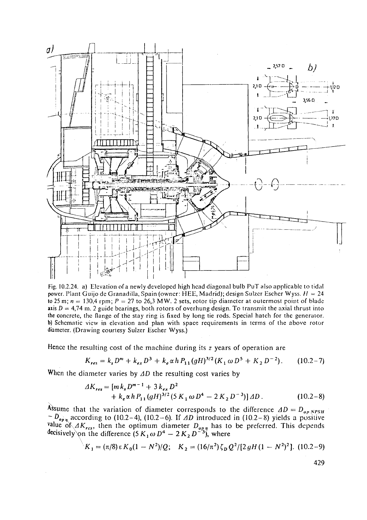
Fig.
10.2.24. a) Elevation of a newly developed high hcad diagonal bulb
PUT
also applicable to tidal
po\llcr. Plant Guijo dc Granadilla, Spain (owner:
HEE,
Madrid); design Sulzer Escher
Wysc.
If
=
21
10
25
m;
n
-
130,4
rprn;
P
=
27 to 26,3
MW.
2
sets, rotor tip diameter at outermost point
of
blade
axis
D
=
4,74
m.
2
guide bearings, both rotors of overhung design. To transmit the axial thrust into
the
concrete, the flange of the stay ring is fixed
by
long tie rods. Special hatch for the generator.
b)
Schematic vicw in elevation and plan with space requirements in terms of the above rotor
diameter. (Drawing courtesy
Sulzer Escher
Wyss.)
Hencc the resulting cost of the machine during its
z
years
of
operation are
When
the diameter varies by
AD
the resulting cost varies by
AK,,,
=
[m
k,
Dm-
'
+
3
k,,
D2
+
k,ak
PI,
(g1i)312(5
Kl
(0D4
-
2K2
De3)] AD.
(10.2-
8)
fibme
that the variation of diameter
corresponds
to the difference
AD
=
D,,,,s,,
-
D,,,,,,according
to
(10.2-4), (10.2-6).
If
AD
introduced in
(10.2-8)
yields
a
positive
value oKAK,,, then the optimum diameter
Do,,
has
to
be
prcfcrred. This depends
decisivelyon the difference
(5
K,
o
D4
-
2
K2
D
-
3),
where
5
-
?
,
b-
L
5
e..
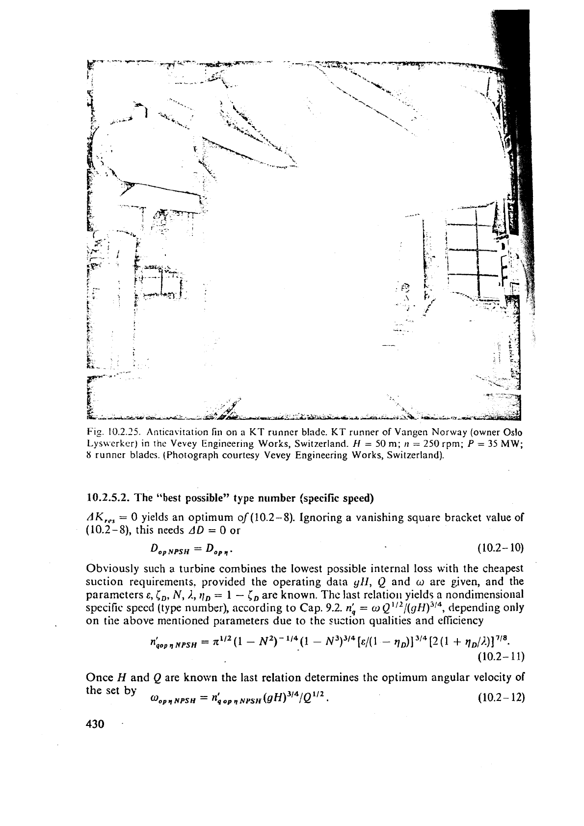
Fig
10.2.25.
Anticavitation
fin
on
a
KT
runner
blade.
KT
runner of Vangen Norway (owner
Oslo
Lys\vcrkcr) in
tiic
Vevey Engineering Works, Switzerland.
H
=
50
m;
tl
=
250 rpm;
P
=
35
MW;
8
runner
bladcs.
(Photograph courtesy Vevey Engineering Works, Switzerland).
10.2.5.2.
The
"best possible"
type
number
(specific
speed)
AK,,,
=
0 yields an optimum oJ(10.2
-
8).
Ignoring a vanishing square bracket value of
(10.2-5),
this needs
AD
=
0 or
Dop
NPSH
=
Dop
q
-
(10.2- 10)
Obviously such
a
turbine combirles the lowest possible internal loss with the cheapest
suction requirements. provided the operating data
yEi,
Q
and
o
are given, and the
parameters
E,
CD,
N,
I.,
tlD
=
1
-
iD
are known. Thc last relati011 yields
a
nondimensio~ial
specific speed (type number), according to Cap.
9.2.
nb
=
o
Q1i2/(gH)314,
depending only
on tile above mentioned
parameters due to the suction qualities and efficiency
Once
H
and
Q
are known
the
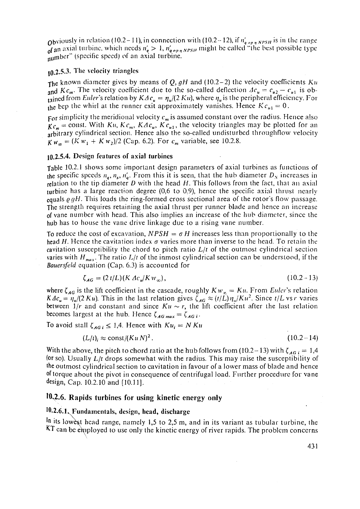
last relation determines the optimum angular velocity
of
the set
by
q
NPSH
=
nb
opq
NusH
(~H)~'~/Q'~~
(10.2-
12)
.
.
Obvio~Sly in rclittion (10.2-
I
l),
in connection n-it11 (10.2-
121,
if
n~,lp,,.,s,,
IS
In
111,:
riln$e
;lxinl turbine. which ilccds
r(,
>
l~z~,,,,~,,,,, might be callcd
"the
he51
possible tgpc
nu&cr" (specific speed) of
an
axial turbirie.
The known diameter gives by lneans of
Q,
gH
and (10.2-2) thc velocity coeficients Klr
and
Kc,,.
The velocity coefticicnt due to thc so-called deflection
dc,
=
cU2
-
c,,
is ob-
t3ined from E~lev's relation by
KA
c,
=
q,/(2
Ku),
where I!,, is the peripheral efficiency. For
the bcp the whirl at the runner exit approxirnately vanishes. Hence
Kc,,,
=
0.
for sin~p!icity the meridional velocity
c,,
is assumed constant over the radius. Hence a!so
KC",
=
COIIS~.
With
KII,
KC,,,,
KAc,,,
Kc,,
,
the velocity triangles may be p1ot:ed for
an
cylindrical section. I-Ience also the so-called undisturbed throu~hflo\v velocity
K
=
(1;
lvl
+
K
1v2)/2
(Cap. 6.2). For
c,,,
variable, see 10.2.8.
10.2.5.4.
Design
features
of
axial
turbines
Table 10.2.1 shows some i~nporlant design parameters of axial turbines as filnctions of
the specific spccds
I],,
II,,
11;.
From this it is seen, that the hub diameter
D,
increases in
relation to the tip diameter
L)
with the head
H.
This follows from the fact, that all axial
turbine has a large reaction degree (0,6 to
O.9),
hence the specific axial thl.ust nearly
equals
@OH.
This loads the ring-formed cross sectional area of the rotor's
flow
passage.
The strength requires retaining
the axial thrust per runncr blade and hence an increase
of
vane number with head. This also implies an increase of thc
hub
diamcter, since the
hub has to house the vane drive linkage due to a rising vane number.
To reduce the cost of excavation,
NPSH
=
G
H
increases less than proportionally
to
the
head
H.
Hence the cavitntiori index
a
varies more than inverse to the head. To retain the
cavitation susceptibility the chord to pitch ratio
Llt of the outmost cylindrical section
varies with
H,,,,,.
The ratio
I,/t
of the inmost cylindrical section can be unders~oncl, if the
Bauersjkld
equation (Cap.
6.3)
is accounted for
where
c,,
is the lift coefficient in the cascade, roughly
K
~r?,
=
Ku.
From
Errlcr's
relation
K
Ac,
=
11,,/(2
Ku).
This in
the
last relation gives
iAG
%
(t/L)
rl,,/~~r2.
Since tlL vs
r-
varies
between
1/r and constant and since
Ktr
-
I., the lift coefficient after the last relation
-
becomes largest at the hub. I-Ience
CAG
,,,,
-
I,,
,.
To avoid stall
CAGi
I
1,4. Hence with
Ku,
=
N
Ku
With the above, the pitch to chord ratio at the hub follows from
(10.2-
13)
with
lAG
=
1,4
(or
so). Usually Llt drops somewhat with the radius. This may raise the susceptibility of
the outmost cylindrical section to cavitation in favour of a lower mass of blade and hence
of
torque about the pivot
iri
consequence of centrifugal load. Ftirther procedure for vane
design, Cap.
10.2.10 and [10.11].
ra2.6.
Rapids
turbines
for
using
kinetic energy
only
10.2.6.1,~undamcntals,
design,
head,
discharge
\
In
its 1owef;t head range, namely
1,5
to
2,5
rn,
and in its variant as tubular turbine, the
KT
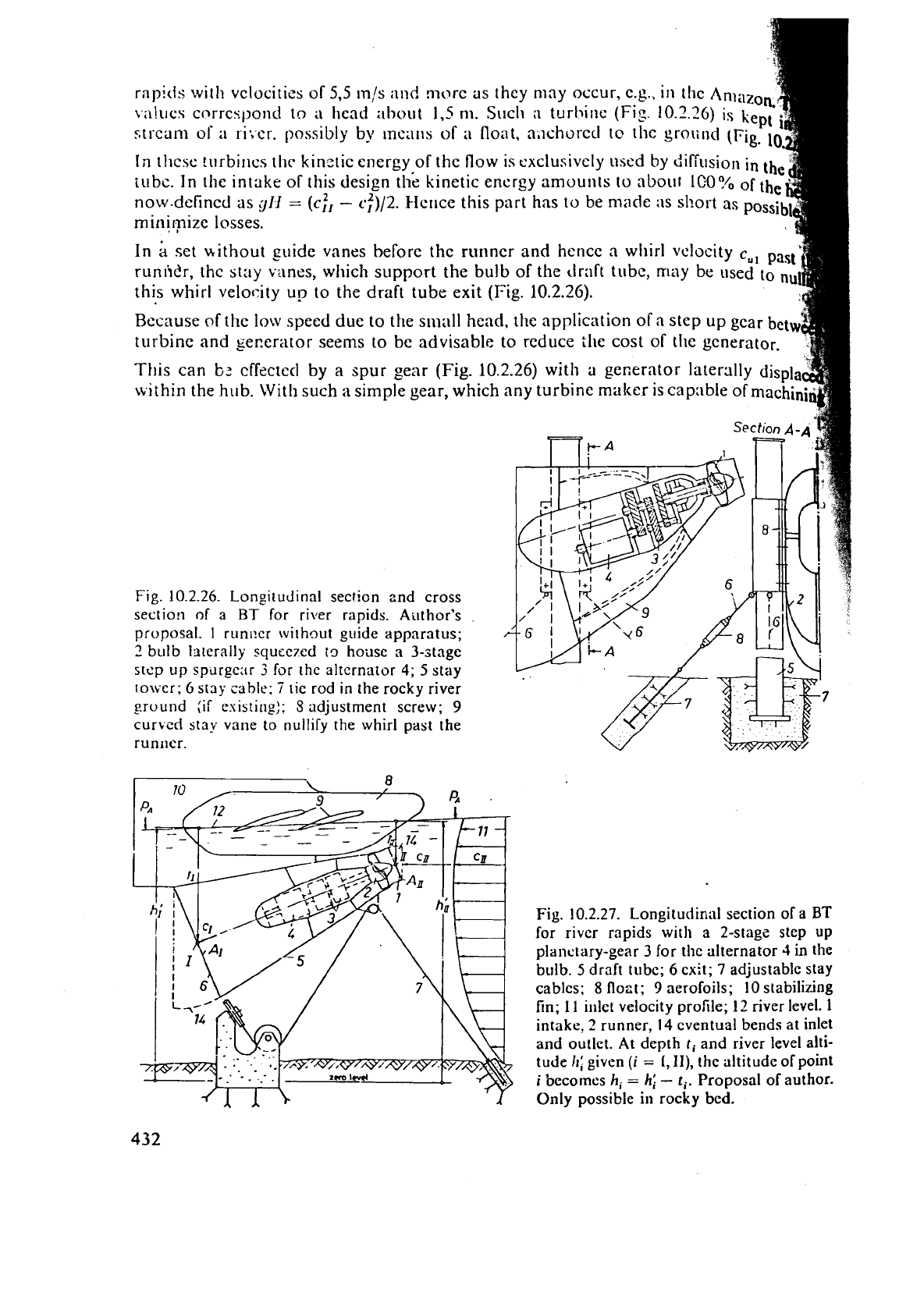
can be ekpployed to use only the kinetic energy of river rapids. The problc~n concerns
\
4
rapids
with vclocitiss of
5.5
m,!s
i111d nlorc 3s they may occur, c.g.. in tbc Am;lzok~
\;iluec
corrccl,ond to
a
head :~hout
I,
nl. Such
:I
turllil~e
(Fi:.
10.2.26)
is kept
stream ol
;I
si.:er. possibly
by
1nc:liis
of
a
float. a.lchorccl to the pro~illd
(Fig.
10,
-
In
tlicse !urbines thc kinztic energy of the flow is
exclusively
used
by difrusio~i
in
th
elr(
iubc.
In the intake of this design the kinetic encrgy amounts to about
IFO?/o
ofthehi
now-defined as
glI
=
(ci,
-
c:)/2.
Flcrice this part
has
to be made
:IS
sl?ost as
possibli
minirnize losses.
>
4
In
b
set uithout guide vanes beforc the rullner and hence a whirl velocity
c,,,
Pal
runir?r, the stay vanes, wliich support the bulb of the dr;lft tube, may be used
to
nu,,,
this whirl velor-ity up to the draft tube exit
(Fig.
10.2.26).
.d
Because of thc low speed due to the srllall head, the application of a step up gear
betv
-7
turbine and sererator seems to be advisable to reduce
the
cost of tile generator.
";
This can
L;:
cffectetl by a spur gear
(Fig.
10.2.26) with
a
ge~erntor laterally displa$
tvi
thin the hub. With such
a
simple gear, which any turbine maker is capable of machiniC
Section
A-A
B
-
A
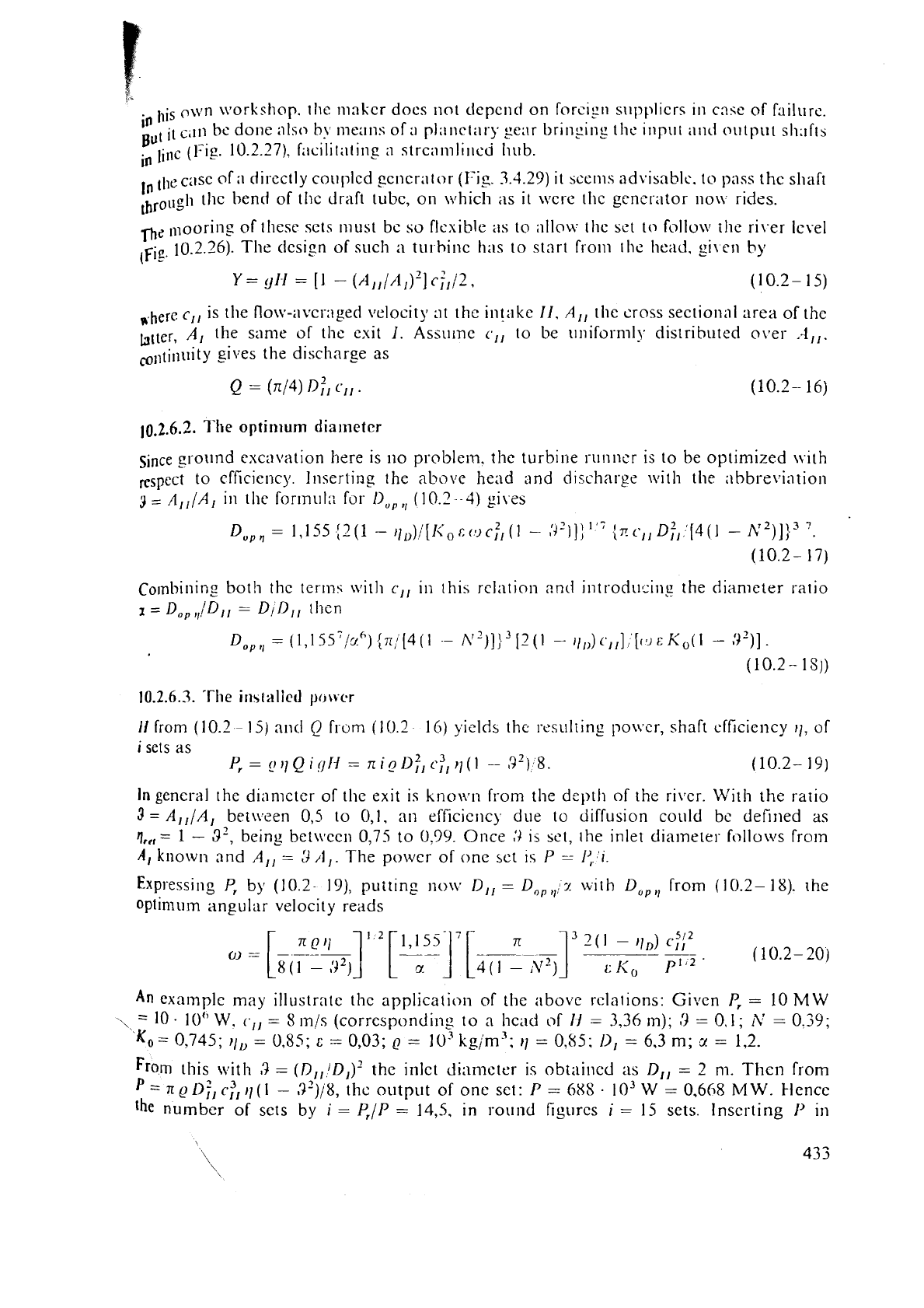
Fig. 10.2.26. Longitudinal section znd cross
section
of
a
BT
for
river
rapids.
Author's
proposal.
1
run1:cr without guide apparatus;
2
bulb 13terally squec7ed to house
a
3-stage
step
up
sprlrgcar
3
for
the
alternator
4;
5
stay
towcr;
6
stay
cable;
7
tie
rod
in
the rocky river
ground
(if
esisting):
S
adjustment screw;
9
curvcd stay vane to
nullify
the whirl past the
runner.
Fig.
10.2.27. Longitudinlll section of a
BT
for river rapids
with
a 2-stagz step
up
plai~ctary-gear
3
for the alternator
4
in
the
bulb.
5
draft tube;
6
exit;
7
adjustable stay
cables;
8
floet;
9
aerofoils; 10 stabilizing
fin;
11
ir~let velocity profile;
12
river
level.
I
intake,
2
runner,
14
eventual bends at inlet
and outlet. At depth
ti
and river level
alti-
tude
hi
given
(i
=
L,
II),
the altitude of point
i
becornes
hi
=
hi
-
ti.
Proposal of author.
..
--
Only possible
in
rocky bed.
llis
ow11 \vorkshop. tllc ~nnkcr docs not depend on fnrc~~ri sllpplicrs in cnqc of hilure.
in
It
c.111
he
done
~ISO
h\.
means of
i1
plilll~till.).
EC:I~
br~nying th~ ~lipllt illid 011tp~1t
S1l.lfth
But
lint
(1:lg. 10.2.27). f;~c~l~t:it~ng
:I
stre;iml~lled Iiub.
case of :I directly coi~plcd 2cncr:ltor
(Fig.
3.4.29)
it
sccms
advisable.
to pins the sllaft
,hrougI~ the bend of thc draft tube, on \ilhicli as
it
\ircre tllc gencrntor no\\ rides.
nc
llloorine of tllese sets 111ust bc so flexible
;IS
to illlow tlic set to follo\v the river lc\-el
.,
10.2.26). The (Icsi2n of such
;I
ti11
hinc has to start from the head. gi\en
by
(Fie
Y
=
91-1
=
[I
-
(A,,/A,)~]
cf,
j2,
(10.2-
15)
,,,here
c,,
is the flo\t.-averaged velocity at thc intake
11, A,,
the cross sectional area of thc
biter,
A,
the same of the exit
I.
Assume
c,,
to be ~lniformlj. distributed o\.er
..4,,.
colltinuity gives the discharge as
Since
ground cxcn~~ation here is no problem. the turbine 1-un11cr is to be optimized \vith
to efficiency. Inserting the
above
head rind discharge
\\lit11
the ;~bbreviation
3
=
A,,/A,
in the formul:: for
ll,,,,
(10.2
-4)
gi1.e~
Combining
both thc terms wit11
c,,
in this relation
2nd
introducing the diameter ratio
I
=
Dog
l,,/Dl,
=
DilllI
then
ti
from (10.2
-
15)
ant1
Q
frum (10.2
16)
yields the rcsulring po\\.cr, shaft ef'ficicncy
11,
of
i
sets as
~=~~~lQi~jN=ni~~f~~~~~~(l
-,'J2)8.
(10.2-
19)
In
general the dtnmclcr of the exit is kno\~rn from the depth of the ri\.cr.
\lit11
the ratio
3
=
A,,/A,
betiveen 0,5 to
O,I,
an efficicnc) due to diffusion could be defined
as
g,,,
=
1
-
3',
being
between
0,75
to
0.99.
Once
,')
IS
bet, [he inlet diameter follows from
A,
known and
A,,
=
3
/Il.
The power of one sct
IS
P
-
1:
1.
Expressing
P,
by
(10.2-
19),
putting
no\v
Dl,
=
D,,,!z
\i;ith
I),,,,
from (10.2-
18).
rhe
optimum angular velocity reads
An
example may
illustrate
the application of the above rclatlons: Given
P,
=
10
MW
-,
=
10
-
10" W.
(.,,
=
8
m/s (corresponding to a hcad of
1-I
=
3.36
m);
3
=
0.1
;
A'
=
0.39;
KO=
0,745;
I,,
=
0,85;
c
=
0,03;
p
=
10%g/ms;
11
=
0,85;
11,
=
6.3
m;
3
=
1,2.
From
this with
8
=
(D,,/D,)'
the inlet di;imotcr is obtaiiicd
as
Dl,
=
2 m. Thcn from
=
IT
ilf,
c:,
11
(
l
-
,9')/8,
thc outp~it of onc sct:
P
=
6x8
.
1
O"
W
=
0,668
M
W.
klencc
Ihe numbcr of scts
by
i
=
Y,/P
=
14,s.
in round figi~rcs
i
=
15 sets. Inserting
I-'
irl
(
0
2
-
0
I
=
I,
r
I
I
(0
I
=
I5
rp!n.
I
ICIIC~
thc rullller blild
\;x.ckl
11
=
0,j
(1)
Y
Dl,
_-
Itl:!
111
s
W~th ~lic Iicatl Ihc cocl'licicrit
oI'
bladc
lip
KII
=
2.-13.
~I;I\
r:~tlicr 111gIl
V,IILIC
co~.rc~poritIs
to
Io\v
1ic;id. Tlic
flt~~
resl~lt~
CJ~.
10
2
i
Q
:
2.3
111
',
5,
whc~lcc
ib1111
ytl
=
3
1
.S
rn',
s'
Ilic type
n
,I;
=
(11
Q1
2,([11/)'
=
4.67,
or
11,
:!l,ou~
1000
(see
l'ablc
10.3.1).
Furtlicr
D
=
=
6,5
m
s;
/),
-
18.4 Kotntion;\l spcet!
realized:
11
-
156
for
;i
grid with
GO
Hz.
C.",
.
10.2.7.
Sornc remarks
abol~t
the
riirlr~er
chillnber
arid
distributor
'#
7
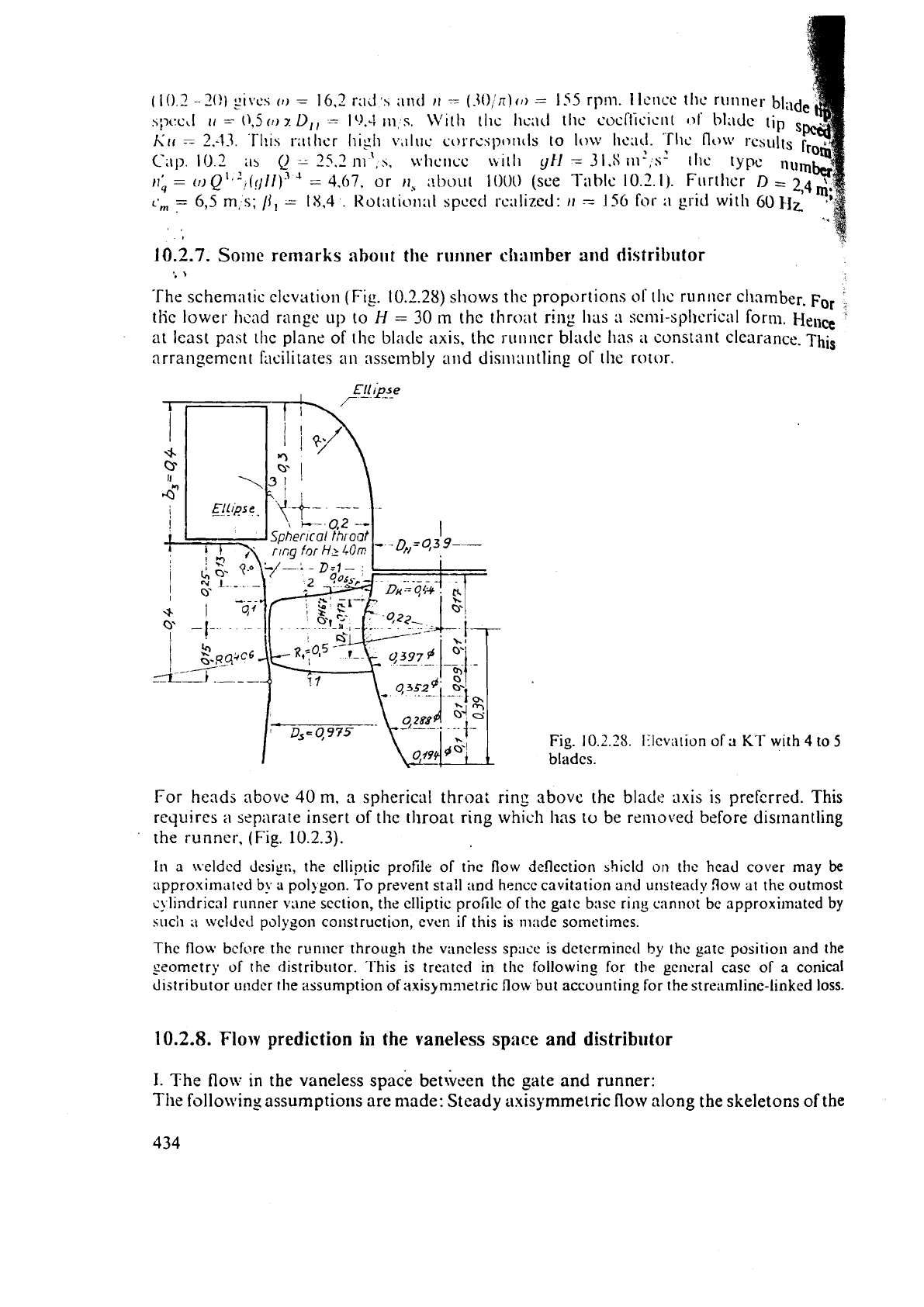
The schern;~tic elevation (Fig. 10.2.28) sho?vs thc proportions
of
lhc runner chamber.
F~~
,
tHc
lower
hcad
range up to
H
=
30
m
thc throat ring Iias
a
sc~ni-spIlt.rical form.
Hell@
at least past the plane of the blncle
axis,
the runncr black has
ii
constant clearanct..
hi^
arrangement Facilitates all asscrnbly and dis~iin~itling
of
the rotor.
Fig.
10.2.25.
Illcvalion of
a
KT
with
4
to
5
bladcs.
For heads above
40
m,
a
spherical throa: ring above the blade
axis
is preferred. This
requires
a
separate insert of the throat ring which has
to
be rerno\:ed before dismantling
the runncr, (Fig.
10.2.3).
I11
a
nelded
clcsigt;,
the elliptic profile of tnc flow deflection shicld
on
thc head cover may
be
appro.uim,rtr.d
b!.
a
pol~pon. To prevent stall and hence cavitation and
uristeatly
flon~
at
the outmost
s!
I~i~d~i~al
runner
vrlne section,
the
elliptic proiile of thc gatc bnsc
ring
cannot bc approximated
by
huch
,i
bvcldcti polygon construction, even
if
this
is
made
sometimes.
The flow bcfore thc runricr through the v;incless
spacc
is dctcrminccl
by
thc gatc positio~~ and the
seomctry of
the
ciistribtltor. This is trentcd
in
thc
followin_g
for
the gcncral case of a conical
distributor
under
the itssumption of axisynin~etric flow but accounting for the streamline-linked loss.
10.2.8.
Flow prediction
in
the
vaneless
space
and distributor
I.
The
flow in the vaneless space between the gate and runner:
The following assumptioris
are
made: Steady axisymmetric flow along the skeletons of
the
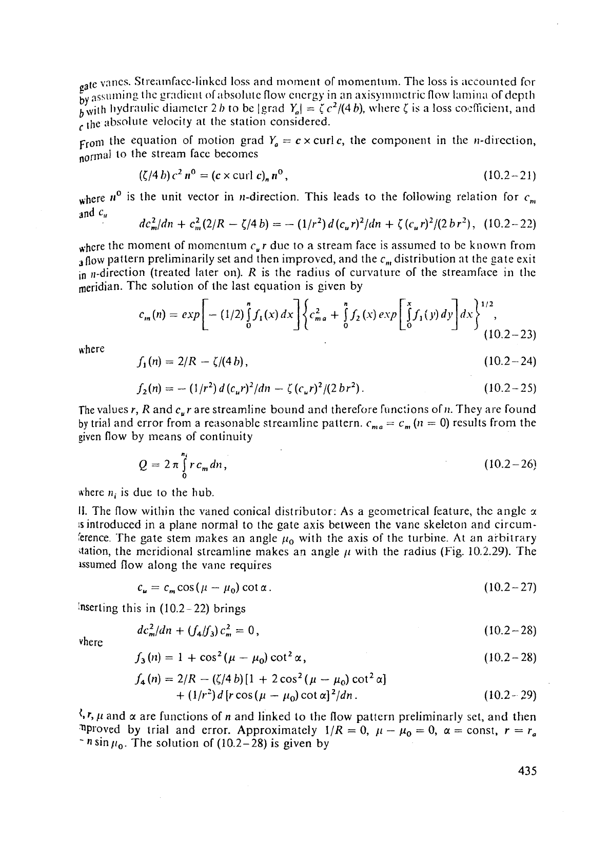
Pa
1,
v;~ncs. Stre:imLlcc-linked loss and nlo~ne~lt of momentum.
The
loss is accounted for
try
nsst~ming
thc grndie~it oliihsolute flo\v cllcrgy
in
an nxisymmetric
flcw
l:lnii~l:~ of depth
bsilh liydral~lic dia~netcr
2
1)
to be (grad Y,I
=
ic2/(4 b),
\~~lirre
is
a loss col:f!icient, and
the ;lbsnlute velocity at the station considered.
Frolll the equation of motion grad
Ya
=
c
x
curl
c,
tile component in the
11-direction,
norlnel to the stream facc becomes
([/4
h)
c2
rio
=
(c
x
curl
c),
ti0
,
(10.2-21)
*,here
rro
is the unit vector in 11-direction. This leads to the following relation for
c,,
and
c,,
dc;,/dn
+
ci,
(2/R
-
[/4
b)
=
-
(1/r2) d (c, r)2/lin
+
[
(c,,
r)2/(2 b r')
,
(
10.2
-
22)
*-here
the moment oC mo~nentum
c, r
due to
a
stream face is assumed to be kiio~\.n from
flow pattern preliminarily set and then improved, and the
c,,,
distribution at the gate exit
in
,,-direction (treated later on).
R
is the radius of curvature of the streamface
in
the
meridian. The solution of the last equation is given by
where
(n)
=
2/R
-
CI(4
h),
f2
(n)
=
-
(1
/r2)
d
(c,
~)~/dr~
-
[
(cu
r)2/(2 b r2)
.
(10.2-25)
The values
r,
R
and
c,
r
are streamline bound and therefore func:ions of
11.
They
are
found
by
trial
and
error from a reasonable strea~nline pattern.
c,,,
=
c,
(iz
=
0)
results from the
given flow by
ineans of continuity
where
ni
is due to the hub.
11.
The flow within the vaned conical distributor:
As
a geolnetrical feature, the anglc
r
is
introduced in a plane normal to the gate axis between the vane skeletorl and circum-
rerence. The gate stem makes an angle
11,
with the axis of the turbine.
At
an arbitrary
itation, the mcridional streamline makes an angle
11
with the radius (Fig.
10.2.29).
The
lssumed flow along the
vane
requires
C,
=
C,
cos
(11
-
pO)
cot
a.
(10.2- 27)
hserting this in
(10.2-22)
brings
f4
(n)
=
2/R
-
([/4 b)
[1
+
2
cos2
(p
-
p,)
cot2
a]
+
(111-9
d
[r
cos
(p
-
/lo)
cot
a]
'/dn.
t.
r,
11
and
a
are functions of
n
and linked to the flow pattern pre1imina:ly set, and then
nproved
by
trial and error. Approximately
1/R
=
0,
/I
-
p,
=
0,
a
=
const,
r
=
r,
-
n
sin
/lo.
The solutiori of
(10.2-28)
is given
by
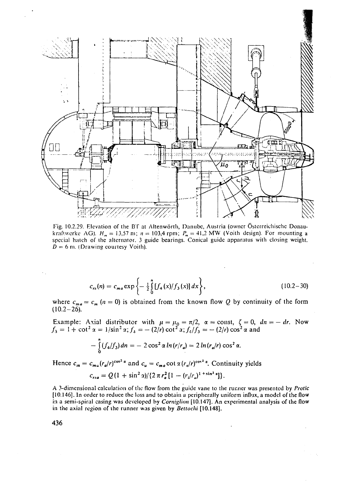
Fig.
10.2.29.
Elevation of the
B'r
at /\Itenworth, I>:tnubc, Austria (owner &terreicliischc
Donau-
krnfttvcrkc
AG).
H,,
=
1337
nl;
11
=
103,4
rpm;
P,
=
41.2
MLV
(Voith design). For rnounting
a
special hatch of the alternator.
3
guide bearings. Conical guidc apparatus with closing weight.
D
=
6
m. !Ilrawing courtesy Voith).
where
c,,
=
c,
(n
=
0)
is obtained
from
the known flow
Q
by continuity of
the
form
(10.2-25).
Example:
Axial
distributor with
11
=
11,
=
n/2,
a
=
const,
[
=
0,
dn
=
-
clr.
Now
A
=
1
+
cot2
x
=
],/sin2
r;
j;
=
-
(2/r)
cot2
a;]:,./
f,
=
-
(2/r)
cos2
cc
and
,
cos2
a
Irt
(r/ra)
=
2
In (r,/r)
cos2
a.
-
ju4~j,)dn
=
-
0
Hence
c,,
=
c,,
(r,/r)'""
'
and
c,
=
c,,
cot
x
(r.,/r)c0'2
".
Continuity yields
c,,,
=
Q(l
i-
sin2r)/(2nr:[1
-
(~'~/r~)~+~~"~']).
A
3-dimensions:
calcula!ion of thc flow from the euide vane to the rucncr was
presented
by
Protic
[10.146].
In
order to reduce
the
loss and to obtain
a
peripherally uniform inflllx, a modcl of the flow
ill a semi-spiral
casing
was developed
by
Cornigliorz
[10.147].
An experimental analysis of the flow
in
the axial region of rhe runner was given by
Bettochi
[10.148].
