Raabe J. Hydro power - the design, use, and function of hydromechanical, hydraulic, and electrical еquipment
Подождите немного. Документ загружается.

10.2.9.
Tidal
power
turbines,
layol~t
1.
~eneral rcnl~i~rks:
The
low hc~d dile to thc lidss prcdcter-mi~~cs the axial tl~rbine
in
its
desigll as a
BT,
ST
0:.
a
?'T
(scc
Fig.
10.2.15)
to
harness tidal po~vcr. For the case
nf
double
acti~~l
plants with one basin (Fig.
10.2.30,
1
b),
this is done by a rnncliine cap;tblc
of
direct
and reversed turbining, and
-
if
necessary
-
also of direct atid reversed pi~tnpi~~g, see
F~s
1.6.2.
~]~crt'Kare the special features of such an axial tubular pump-turbine for direct and
reversed flow
in
both the modes of operation are considered.
Imagine a turbine of the bulb type (Fig.
10.2.15).
The flow enters the runner from the side
of
the bulb with a whirl produced in the stay and mainly in the griidc \.anes of
il
co~lical
distributor.
In
this case of
n
so-called direct
flo\v
whilst turbinillg. the draft tube operates
as
a
diffi~ser. Ob\liously this works at a higlier efficiency as
a
turbine t!lan under reversed
flow,
when
the gate operates
as
a diffuser.
This direct
turbining usually is combined with
a
flow from the reservoir to the ocean
[10.149].
If the basin is situated
at
the mouth of
a
river, then
ill
consequence of the latter's
energy, larger work is done, combined with
a
higher efficiency.
When
reversedly turbining, the in!et whirl of the rotor vanishes, as the draft tube is not
equipped \vith vanes. Then the channels between the guide vanes operate, evcn if undc~
modest pressure recovery, as a diffuser. For the design of gates, it is important thai in
enlergency they close tight.
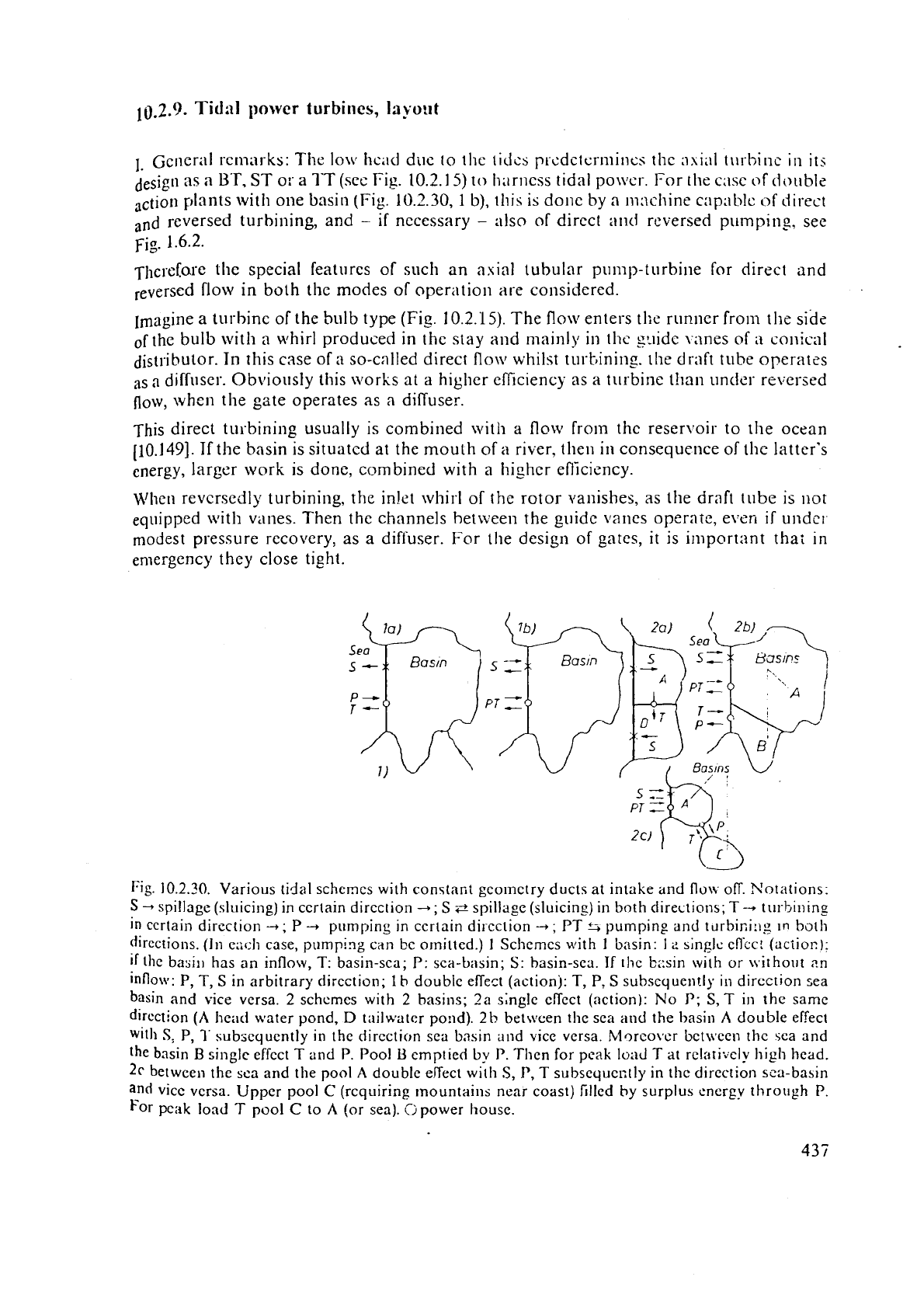
Fig.
10.2.30.
Various tidal schemes with constant geometry ducts at intake and
flow
off. Notations:
S
-,
spillage (sll.licing) in ccrtain direction
+;
S
e
spillage (sluicing) in both clireotions;
T
-
till-bining
in certain direction
4;
P
4
pumping in ccrtain dircction
-+;
PT
%
pumping and t~lrbiniilg
In
bat11
(jirections. (In c;~cl~ case, pimping can bc omitted.)
I
Schemes with
1
basin:
12
single
effcc! (action);
if
the basill has an inflow, T: basin-sea;
P:
sca-basin;
S:
basin-scu.
If
thc b::sin with or ~virhorlt an
inflow:
P,
T,
S
in arbitrary dircction;
I
h
double effect (action): T,
P,
S
subsequently in direction sea
basin and vice versa.
2
schemes with
2
basins; 2a single effect (action): No
P;
S,
T
in the same
direction
(A
head water pond,
D
tailwatcr pond).
2b
between the sea
and
the hasin
A
double effect
with
S;
P,
2'
subsequently
in the dircction sea b3sin and vice versa. R.lorcover bet\vcen the sea and
the basin
B
single effect
T
and
P.
Pool
U
cmptied
by
P.
Then for
peak
load
T
at rclativcly high head.
2~
between the sca and the pool
A
double effect with
S,
P,
T
subsequectly in the dircction sea-basin
and
vice versa. Upper pool
C
(requiring mountains near coast) filled by surplus energy through
P.
For
pcak load
T
pool
C
to
A
(or sea).
O
power house.
.T'tic:rci;~rc nearly untwistt-cl v;;ncs arc nectlcd. For tlie diffcrc~it operations :lnd
tile
,-orre.
spol:ding g:rtc positions. tl~c stroke of t:ic g;rtc
servomotor
~niist
IIC
ratlicr loiig. I-lowever
*,
this c:ln I)c oh[,linccl e,lsily on
a
stationary part.
3
*
r*
C:ontr:iry to the above. the rotor with its overhung design nceds
a
b1:ldc ildjustment
di
mech;lni\ni with tlic s~iiollest possible stroke. Thcrefore
it
scelns ;ldvis;lble to operate the
pump-turbinc under all its modes of operation with ncarly one and the same position
of
3
the rotor blades.
For a lack of sufficient
tinic between the different operations, due t9 speeds, reversed
to
each' btiier, the rotor vanes should also be capable of operating as
a
hydraulic brake. rhus
a
pitch to chord ratio below
1
should enable a turnover of the blades through the closed
'
position.
11.
Some peculiarities of tlie velocity triangles during dlrect and reversed turbining and
pumping: Contrary to thc use made so far in this book, the rotor edge towards the
reservoir is dcr,oted by subscript 2 and the opposite edge with
1.
I
1)
Direct turbining: Flow from the distributor to thc: draft tube. Vane arlgle at overgate
about
70-.
On the rotor inlet,
a
whirl in the sense of speed
ti.
Relative flow at rotor inlet
more inclined to the circunlfcrence than at the exit. Zero whirl at the rotor exit
(c,,
=
0).
Hence (Fig. 10.2.3
1.1)
n
forward curved rotor vane is required. Flow from basin to ocean.
2) Direct pumping: Flow from basin to ocean. Gate angle of 90" frrcilitates
a
vanishing
whirl at the rotor inlet. At the rotor exit, whirl is in
the setlse of ratation. Sirice this gives
a bad prcssille recovery, :dso
a
gate angle of more than
90"
may be applied, which causes
a whirl
at
the rotor Inlet contrary to its speed but avoids the whirl at the outlet. Rotation
in
tlic scilst. of casc
1).
Compared with c;ise 1) the rotor requires backward curved vanes
(Fis.
10.2.31.2).
3)
licver;t.d turhining: Flow from ocean to basin and from draft tube to gates. Rotation
reverses its sense compared with 2). Therefore fast
brakin2 is required at the end of the
foregoing operation
2)
by
turning the blades through its zero position in a plane normal
to the
axis.
The
gates
now opened by about 90" operate as a part of diffuser. For the
generation of torque, thc whirl at the rotor exit must be opposite to the latter's speed,
since
c,,,
=
0.
Now
back:vard curved vanes required as in case
2)
(Fig. 10.2.31.3).
4)
Reversed pumping: Flow from ocean to basin. Zero whirl at rotor inlet. Hcnce at the
rotor
exit, whirl is in the di~ection of rotation. Gates, now operating as a part ofa diffuser,
make
an
angle about 90' with the circumference. Forward curved rotor vanes are re-
quired
(Fiz. 10.2.31.4), as in case 1).
To reverse the
speed for transition frcm
4)
to l),
a
turnover of rotor vanes for braking
is required.
Fig.
1.6.2 shows the timing of the operations 1 to
4
needed for a one pool
double effect tidal power plant,
e.g. the French "Rance".
Conclutling, the following requirements can be stated for the design of a tubular pump
turbine, for direct and reversed flow, in both the modes of operation, for such a tidal
power plant:
a) The stroke of the gate must enable a gate-position of about
90"
with the circumference.
The
sate vane must be rounded at both its ends, since they may both serve as entrance
(,Fig. 10.2.3 1.5 a).
b) The rotor vane ad;ustn~ent must enable
a
vane position of about 20" with the circum-
ference for normal operation and a position of
-
10"
for brakirg (Fig. 10.2.31.5
b).
C)
The required camber of the roior blade is the same for direct turhining and reversed
pumping,
namely that due to forward curved blades. For the other two operations
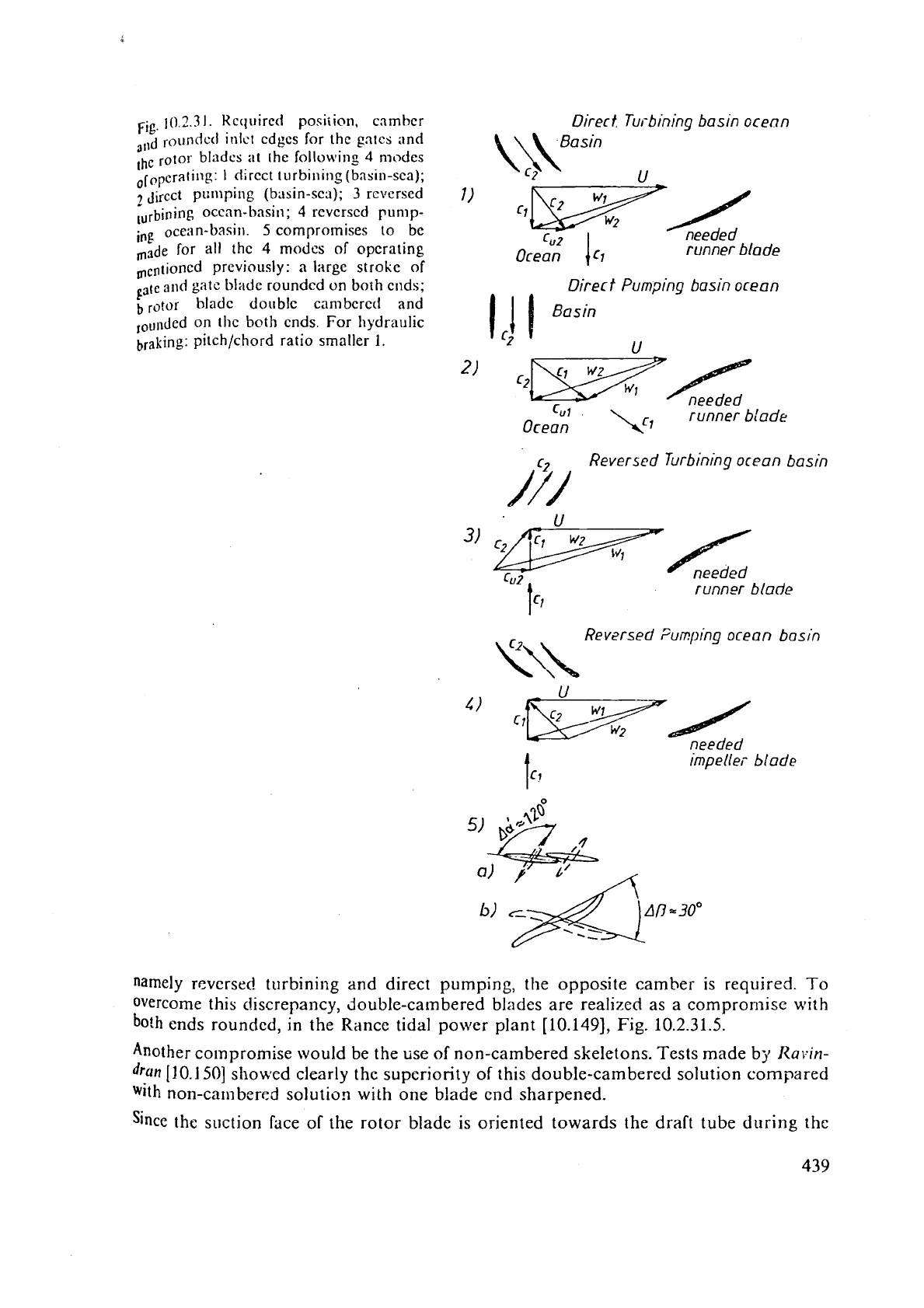
Fig
10
2.3
1.
Kccll~ired posiiion, camber
Direr
t.
Turbining basin ocenn
311d
roundctl irllct cdgcs for the
gntcs
and
,hc
rotor bladcs at rhe following
4
modes
ofoPcrating:
1
direct turbirling(basin-sea);
jircct pumping (basin-sea);
3
rcversed
7)
;urbining ocean-basin;
4
rcvcrscd pump-
ing
ocertn-basin.
5
compromises to
bc
Gz
needed
In3de
for all
thc
4
modes of operating
runner blade
rncntion~d previously:
a
large stroke of
and
gate
blade
rounded on
both
cnds;
Direr
f
Pumping basin ocean
t,
rotor hladc doublc cambered and
l,u~~ded on the
both
cnds.
For hydraulic
braking: pitchlchord ratio smaller
1.
11
*)
c2-f
-
needed
LuI
.
runner
blade
Ocean
Reversed Turbining
ocean
basin
/7/
3)
*/
CUZ
needed
tcl
runner
blade
Reversed
Fumplng
ocean
basin
Y\\
Cr
needed
irnpelle,-
blade
namely
reversed turbining and direct pumping, the opposite camber is required. To
overcome this discrepancy, double-cambered blades are realized as a compromise with
both ends rounded, in the Rance tidal power plant [10.149],
Fig.
10.2.31.5.
Another
colnpromise would be the use of non-cambered skeletons. Tests made by
Rayin-
dran
[10.150] showed clearly the superiority of this double-cambered solution compared
with
non-cambered solution with one blade end sharpened.
Since the suction face of the rotor bladc is oriented towards the draft tube during the
operiltio~i-;
I!
ancl
4)
and oriented tow;~rds tile g.ltes during the opcr:ltions
2)
and
31,
hot
the f;~ccs
ol
thc ro!or bl:ldc ~nurt be li~iisbed s~lioollily so as to R~~~ction
as
a
suction
raw
cI)
Tlie guide hc:lrings of the sct havc to enable lubric:ition in hot11
SCIISCS
of rotatiOK
8
C)
Silicc tllc
il~iill
thrust chiltiges its direction whc'11 the head wntcr clinnges
from
the
.+
Imsin to tllc oceiln, ttie sct nceds two thrust berlrings for both axial flow directions.
,,
f)
Tlle distributor with
its
adjustable gales must operate as
a
ili!Tilscr in the case of the
-$
"b
revccsed turbine
:lrliI
direct pump flow. Therefore both ends of the distributor vanes mus<
%
be'proliled carefully. l~ccause of thc rather poor pressure recovery of a distributor
,,
a
clilTuscr the cflic~cncy
of
:I
machine opcrating that way is lower than that of a machine
operating the other
W,IJ
with a draft tube as
a
dinuser.
iJence best efficiency car1 be achieved only, when the flow direction is retained. This
can
be done either
by
complicntcd bifi~rcations and
valvcs
at both encls of the machine (also
draft tubes which
may
bc turned on hinges have been proposed, surely not reliable) or
bq'
a single actio~; working cyclc (Fig.
10.2.33.).
In the largest tidal power unit of Annapolis
Canada (Fig.
10.2.22)
designed by Sulzer Escher Wyss the singit. action was preferred
of
using a Straflo turbine wit11 rim generator,
110.321.
Fig.
10.2.32. Thc sequence of operating modes in a tidal
powcr plaat with
1
basin
and single uffcct (action):
1
filling;
2 waiting plus eventual pumping;
3
turbining.
0
level
sea;
1
2
3
b level
basin;
p.levcl
basin
with pumping. Utility lifted
by
l
l,,,,
,,,,I-
some sets suitcd
to
return
flow. (Drawing courtesy
EdF).
111.
The energy _gain
by
additional pumping: Imagine the head during pumping changes
p:~rabolically with
ti~nc
according to
Hp
=
k
r2.
When
[I,
has rcaclicd a value
H,,,
after
1
period
t,,
tu1-bii~ing starts. Whence
k
=
flp,/tb.
Assumin:. nn electricity rate
ke,
efficiency
q,,
and accounting for unit flow
ell,
whilst pumping, the expenditure during
pumping Secon~es
%'hen the plant turbines without pumping during the period
t,.,
the following profit is
11iadc
by the s;ile of energy at
a
constant turbir.:: efficiericy
11,
and
electricity rate
k,
with
a
unit
flow
Q,
,,
under tilrbining at a head
HTo
Then generating the same time
t,
with a head incrzased by
AH,
as
a
consequellce of
prtmping would increase the profit
by
Ah',
=
(312)
k,qT
Q1 lT@(~pog)3'2
tT(l
-
dN!HPU)
D2.
(10.2-33)
For profitable purnying the ratio
f
=
AKJK,
must be larger than one. Hence
Ascuming
Ql,,!Q,
,,
=
1,3;
11~
=
0,9;
q,
=
0,s; then the condition
f
>
1
leads to
(tp/rr)(l
-
AH/HpG)
>
472.
This gives for
AH/llp,
=
0,2
the time ratio
t,/.rp
>
0,9.
This
proyes the rule that to
make
a
profit
by
pumping, the duration of turl~~ning should
be
equal
or larger than that
cf
pumping.
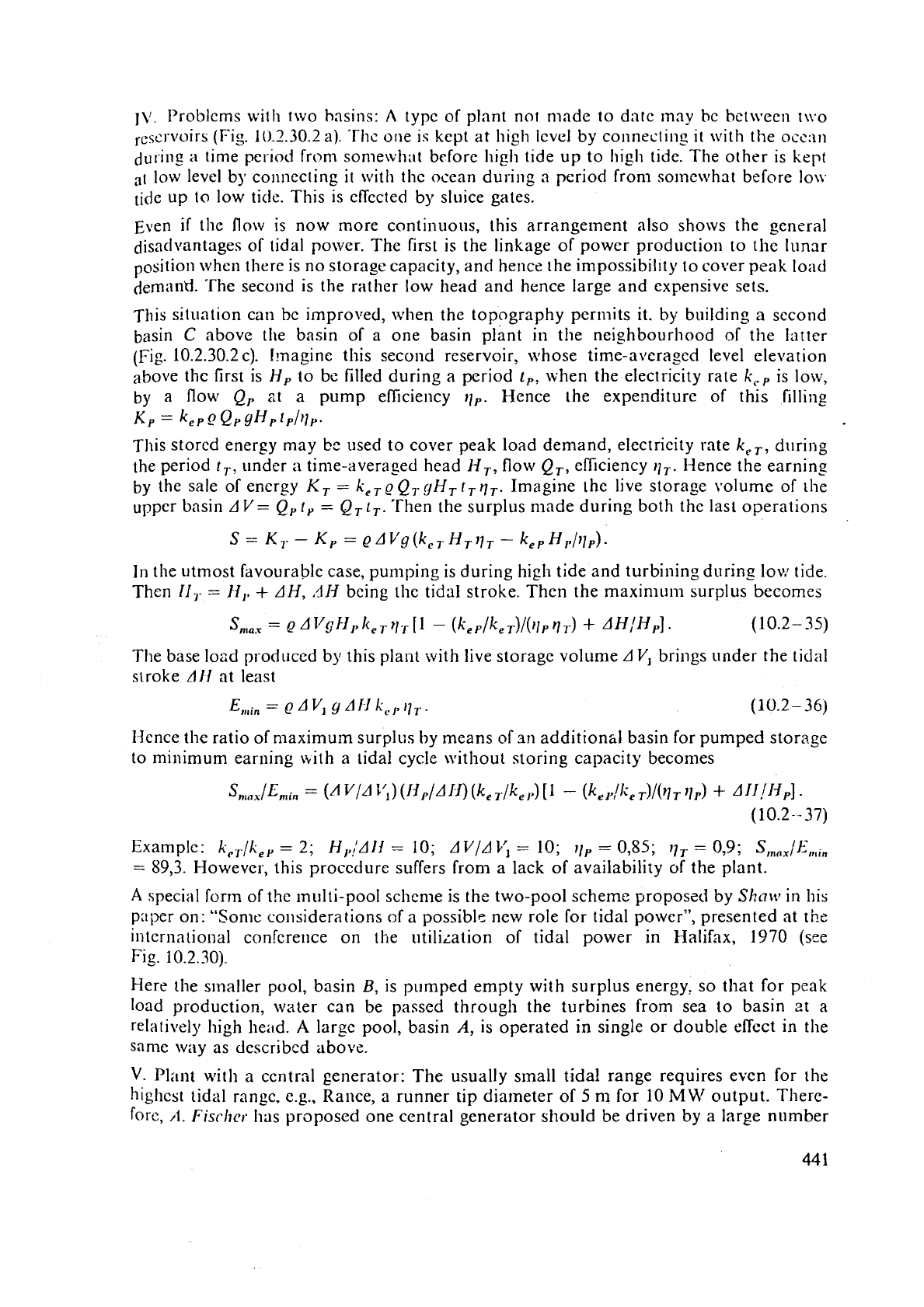
I\'.
Problems with two hasins:
A
typc of plant not made to dntc may bc bet~veen tu.0
rescr~~ir~ (Fig. 10.2.30.2 a). 'The one is kept at high Icvel by connectins
it
with the occ;ln
nu~.illg
a
time period from somewhat before high tide up to high tide. The other is
kept
at
low level by co~lnecting it with the ocean during a period from sorncwhat before lo\v
tide up to low tide. This is eflected by sluice gates.
Even
if
the flow is now more continuous, this arrangement also shows the general
disadvantages of tidal
power. The first is the linkage of power production to the lunar
position when there is no storage capacity, and hence the in~possibility to cover peak load
demand.
The
second is the rather low head and hence large and expensive sets.
This situation can
bc improved, when the topography permits it. by building a second
basin
C
above the basin of a one basin plant in the neighbourhood of the Irltter
(Fig. 10.2.30.2~). Imagine this second reservoir, whose time-averaged level elevation
above
thc lirst is Hp to be filled during a period t,, when the electricity rate
kc.
is lour,
by a flow Qp
zt
a pump elliciency
11,.
Hence the expenditure of this filling
Kp
=
kep
_O
Qp
~Hpfpl~,.
This stored energy may
be
used to cover peak load demand, electricity rate k,,, d~lring
the period
r,,
under
a
time-averaged head
H,,
flow QT, efficiency
q,.
l-lence the earning
by the sale of energy
KT
=
keTeQ,gHTtrqT. Imagine the live storage volume of the
upper basin
AV
=
Q,
t,
=
(2,
t,.
'Then the surplus made during both thc last operations
In the utmost favourable case, pumping is during high tide and turbining during low tide.
Then
11,-
=
H,,
+
AH,
,1Ij
being thc tidal stroke. Then the maximum surplus becomes
The base load produced by this plant with live storage volume
AVl
brings under the tidal
stroke
All
at least
Hence the ratio of maximum surplus by means of
st1
addition&] basin for pumped storage
to minimum earning
with a tidal cycle \vithout storing capacity becomes
sn,oA/Emin
=
(A
v/AJ'l)
(J3f'/A1a
(keT/kel>)
-
(kel>/lieT)/(r~T
+
A1l!ljPl
-
(10.2--
37)
Examplc: k,,/k,,
=
2;
H,,/AII
=
10; AV/AV,
=
10;
11,
=
0,85;
11,
=
0,9;
S
,,,,
/El,,,
=
89,3. However, this procedure suffers from a lack of availability of the plant.
A
special form of the multi-pool schen~e is the two-pool scheme proposed by
Shaw
in his
paper on: "Some considerations of a possible new role for tidal power", presented at the
international conference on the
utili~ation of tidal power in Halifax, 1970 (see
Fig.
10.2.30).
Here the smaller pool, basin
B,
is pumped empty with surplus energy, so that for peak
load production, water can be passed through the turbines from sea to basin
zt a
relalively high head.
A
large pool, basin
A,
is operated in single or double effect in the
same way as described above.
V.
Plant wit11 a ccntr~l generator: The usually small tida! range requires even for the
highest tidal range,
c.g., Rance, a runner tip diameter
of
5
nl for
10
MM1
output. There-
fore,
11.
Fiscltcr. Ilas proposed one central generator should
be
driven
by
a large number

of
(may hc
ui>
to !CO) turbincs by means of hydrostatic gear to savc first cost. Here each
turbine
gcnt'ratt's
a pressur.izcd oil flow by
:i
rnultipiston bcvcl clisk pump.
The flow
resulting
from all the turbincs of one group propcls the rotor of thc ccntral generator,
This can
bc
clone, c.g., by a niultipiston bcvcl disk positivc displaccmcnt motor.
By
adjustment
or
the bcvcl disk in thc ccntral gcncrator, thc gcar ratio bctween turbinc
anci
ahcrnator
can
be
changed
under constant altcrnator spccd.
~htk'the ;aijustable bcvcl disk allows an adaptation of the turbine's optimum
speed
to the head,
whicll varics continuously in
a
titl;tl power plant. Thc improvcd cflicicncy has to compensate the
cost
and
loss
of
cncrgy duc to thc gcar. Moreover such n gcar enables an economically high speed
for
thc altcrnator, which would bc cheaper than a slowly rotating direct couplcd one.
VI.
Plant with turbines for sluicing operation:
A
further increase in energy production
can be achieved if the turbines may run also in the sluicing operation to fill or to empty
the basin, when the water levels of the sea and the basin are nearly the same.
VII.
Economic consideratiotls: In his paper "Choice of hydroelectric equipment for tidal
energy" presented at the Korean tidal power symposium, Seoul in 1975,
H.
lMiller
reported that the direct costs of different Fundy Bay schemes are distributed as follows:
a) Electromechanical equipment 46,7%,
b) Power i.louse
21,6%,
c) Sluice\vays 13,7
%,
d) Dikes 16,3
%,
e) Fixed site cost 1,7
%.
Hence the hydroelectric equipment, directly influences about 50% of the costs, and
indirectly
about 35%, since the power house and sluiceways depend largely on the
machine's sluicing capacity.
For the single pool single effect scheme, an optimally designed turbine can be used.
However, within the usual range of operation
HIH,,
=
0,2 the pump efficiency of the
turbine goes down to 50% of the turbine's bep efficiency. If therefore there is no pumping
a
fixzd b!ade propeller would suffice.
This reduces the machine price by about
12%, together with lower maintenance costs.
Si~ce sufficient discharge is always available, the turbine can always operate at its bep.
Whzn compared with the single effect scheme, the double effect scheme, as
a
compromise,
results
in a lower mean efficiency and in a lower energy output per tidal cycle. Accord-
ingly a larger number of units is required. This decreases the benefit-cost ratio. Hence, the
latest results of studies on Fundy Bay have reconfirmed the single effect schemes to
be
the most economical.
All
rittemp:~ to eliminate, e.g., by added pumped storage, the intermittent energy produc-
tion, are unsatisfactory, since they require:
1)
Increase of investment,
2)
more complicated hydroelectric equipment,
3)
higher maintenance costs,
4) shorter working life.
Therefore tidal power can be economic when it solely converts the available tidal
energy
directly into electric energy.
VIII. The superiority of straflo design compared with bulb design: Again
following
124illur,
simplicity
and
compactness are requirements to make use of caisson constructio*
which has proved so successful
in
the building of dikes. These requirements are
not
fulfilled by the vertical Kaplan turbine or the tubular S-turbine.
file
ilqe of bulb tiirbines for tidal power to d:ltc originated from the fact. th;u
the
1:irgc
~urbinc tlccded was
not
available, and
tli;it
the bulb turbinc
can
fulfil
sc>n;c
of
tllc
Str~
rcquil.cmsnts of
i~
tidal power machine. I-lowever bulb tl~rhirles have some lilnitations.
Collsid~r the gcnerator out put
P=
KD~L~,
,here
K
is thc compactness factor,
DR
the rotor tip diameter,
L
the rotor length. and
11
the spccd.
mc
slim
bulb, hydraulically rcquircd. makcs thc generator rotor dinnicter
D,
considerably sm:llIcr
lhan
the turbine runncr diameter. Therefore, thc gcncrator length
L,
and the compitctncss factor
li
,,,,,t
bc incrcirsed, which both increases thc temperature. This may require complicated \vatu--
cooling
in
a
badly accessible gcnerator even at smaller outputs (about
10
MW).
1hc small rotor diameter results also in a low inrrtii~ of the set. This contradicts the rcquircments
or
stable regulation, rspeciallv when thc plant supplies a grid by itself. Moreover a Ilirge inertia
nJuceS the consequenccs of power swing,
a
tid;il unit is subjected
by
wave-induced pressure
fl,ctuations.
It
would help also to reduce thc fluctuating loading on thc critical connections of the
and
windings due to this powcr swing. l'hesc problenls yield a lo\vcr limit for tlic runner
diameter, which lies, accordi~ig to recent studies
on
Fundy
Bay,
at
7500
mm.
In
the
compact bulb,
it
is dificult to carry out extensive repairs, especially on the stator. Therefore
generator
sliould be removable through a special hatch on the top of the bulb (Fig.
10.2.1
1).
~~rnoving the gcnzrator through the turbinc pit requires removal of the whole unit, jvhich alolie
lakes about
6
months for units of the size needed.
1"
the Straflo turbilie all the disadvantages mentioned above have been eliminated,
namely
1)
50%
larger generator diameter than for a
BT;
effectively cooled generator,
2)
no limitation
to
size of turbine and generator,
3)
3
to 4 times as much inertia makes the gcnerator more stable and stabilizes the
regulation,
4)
turbine and generator in the same vertical plane require only
1
erection pit,
5)
good accessibility to ge~erator.
A
comparison by
hlillcr
bctwcen
a
straflo turbine plant having
18
units,
25
MW
each, and
a
tulb
turbine plant, having
30
units,
15
MW
each; results
in
the following:
At
a width of
421
ni for the
Straflo plant,
thc bulb plant ha5
a
width that is
1,27
times larger, and a price of hydro electric
equipment,
that
is
1,5
times larger than the rcspcctive valucs of thc Straflo piant. Hence tlie Straflo
turbine seems to be
thc tool to utilize tidal power
at
rcduccd cost.
10.2.10.
Runner
design,
simple
procedure
I.
Runner vane design
by
cascade theory:
For
given velocity triangles with their cocffi-
ciellts
h'u,
Kw,,
Kw,,
K
Ac,,
from 10.2.5.3, the maximum lift coeficient at the hub
CAC
=
1,4, with the vane number
z
from Table 10.2.1, the known hub diameter
D,,
the
pitch chord ratio from relation (10.2-
13)
gives the chord
Li
at the hub.
Runner diameter
D,
vane number
2,
the hence given tip pitch and the pitch
to
chord ratio:
from
Table 10.2.1 yields thc chord
La
at the runner tip. Since the inlet edge and rear edge
of
the runner vane should
be
as
straight as possible for reasons
of
stable flow and vane
Strength,
the.pitch chorct ratio and hence the chord
is
given for an arbitrary cylindrical
Rotion, for which the velocity triangles are
also
known. The relation (10.2-
13)
yields the
lift
coeficient in the cascade
c,,.
'Then
fro111 Table 6.2.1 thc ci~scrldc coc.fiicit.~lls
C,,
C,, C,,
C.,
LIIC
cieternlirlcd
:IS
functiolls
ol't/L
a~ld thc anflc
11,
which may be approxinlated to
/I,,
I'rorn tl~c trii~ngles,
as
the angle
)r,
=Z
Or,
+
w2)/2
n~akcs with the circumference. Then from
(6.2-47)
the physical angle
of attack
(So
=
i,,
(C,/C,)
is
obtained.
Now
the
vane
skeleton
must
be set. This may be done with respect to pressure distribu-
tion tcavit;~tion sensitivity) or the hydrodynan~ic torque abaut the pivot of the blade.
Then
~lcicrmination of the angles
9i
the skeleton makes with its chord at Birnbaun~'~
3
stations
(Cap.
6.2-37). Hcnce
K,,
K,,
K,
and then the zero lift angle of attack
6(FA
=
01,
are obt'lincd by (6.2-4). Thus the anglc the chord of the cylindrical sectiorl makes with
the circumference
/I,
=
0,
-t
6
(FA
=
O),.
The skeletons then are built up so that the centre of gravity of each cylindrical section
coincides with the blade axis.
For blades with
a
usual standard profile such as those of the basic Giittinger series or the basic
NACA
scries
[10.151]
the centre of gravity is aproximntely a distance
0,4
L
from the profile's leading
edge.
Hcnce there is no bending stress at the blade's pivot due
to
centrifugal load of the blade.
The
real thickness of the blade must be determined at first on the base of the blade on
the hub.
Mere
the
bending moment as the relevant load caused by the hydrodynamic
lift
may be
approximated as
iV
being the hub to tip diameter ratio,
z
the vane number. The root cross section
of
the
blade on the hub
dlsk is nearly
a
rectangle, whose length equals the diameter
D,
of the
blade disk (Fig. 10.2.33). Roughly
D,
=
0,4
Dlz.
This gives the sectional modulus of this
cross sectional area as
hi,,
0,/6,
where
hmi
is the maximum blade thickness at the hub
section.
VJith the carefully set admissible bending s:ress
a,,
(which is strictly speaking only about
fi
399'0
of the stress acting there, as a consequence of centrifugal load-induced torque,
*
torque due to hydrodynamic lift, to mention the most important ones), the maximum
bl~de thickness is
a
According to
Barp
and
Krller
[10.152], in blades of alloyed chromium steel, the assess-
ment
of
a,3,
has to account for fatigue effects. To reduce the latter a fillet is provided a10
the corner between the disk and the blade. Moreover a rounded cut out should
provided at the corner between the disk and blade in the plan view.
This cut out has to be closed by an insert bolted on the blade to prevent leakage
betwe
pressure and suction face of the blade.
The :hickness distr~bution of the real profile of
a
given cylindrical section based on a certain
seri
e.g.,
IVACA
is set so as to strain the chosen rnodel profile normal to its centre line at any sta
proportiolial to the ratio of calculated maximu~n thickness, to maximum thickness of the
m
profile.
The
mnximuni thickness required at an arbitrary cylindrical section
h,,
drops continuously
wi
radius from its maximum
h,,
on the hub towards a value
h,,
at tip diameter, tolerable for le
and tip clearance cavitation erosion. To reduce the latter. an anti-cavitation fin may be welded
a
a part
of
the blade's tip (sec Fig.
10.2.25).
The fin is usually worn off by tip clearance cavitation
therefore in general not
pravided.
444
50
60
70
80
90
rill
U/rpm
08
1.0
1;2
nll/nll
opt
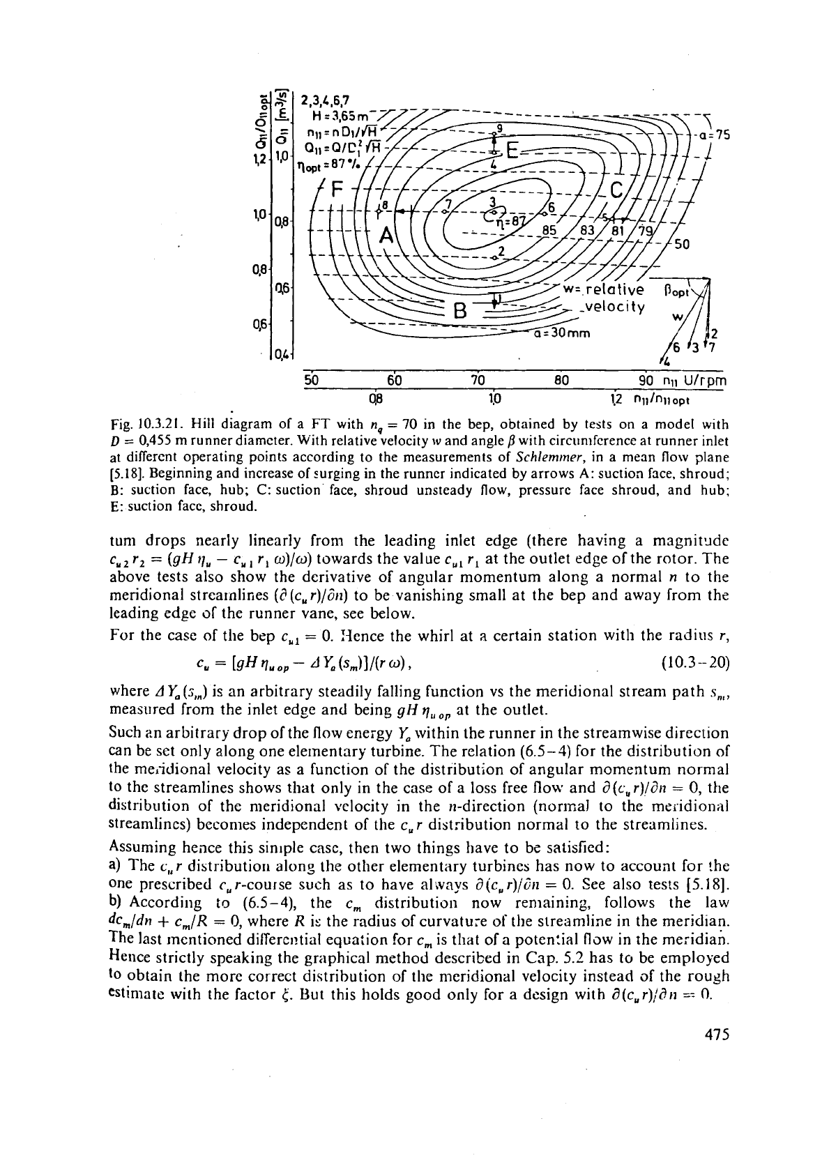
Fig.
10.3.21.
Hill diagram of a
FT
with
n,
=
70
in the bep, obtained by tests on a model with
D
=
0,455
m
runner diameter. With relative velocity
w
and angle
/?
with circumference at runner inlet
at different operating points according to the measurements of
Schlemtner,
in a mean flow plane
[5.18].
Beginning and increase of -.urging in the runner indicated by arrows
A:
suction face, shroud;
B:
suction face, hub;
C:
suction face, shroud unsteady flow, pressure face shroud, and hub;
E:
suction face, shroud.
tun1 drops nearly linearly from the leading inlet edge (there having a magnit~de
c,, r,
=
(gH
9,
-
c,,
r,
o)/w)
towards the value
c,,
r,
at the outlet edge of the rotor. The
above tests also show the derivative of angular momentum along a normal
n
to the
meridional
strea~nlines
(d(c,r)/dn)
to be vanishing small at the bep and away from the
leading edge
of
the runner vane, see below.
For the case of the
bep
c,,
=
0.
Ijence the whirl at
a
certain station with the radius
r,
where
AY,(s,,)
is an arbitrary steadily falling function vs the meridional stream path
s,,,
measured from the inlet edge and being
gH
quo,
at the outlet.
Such
Zn arbitrary drop of the flow energy
Y,
within the runner in the streamwise direction
can be
sct only along one elementary turbine. The relation
(6.5-3)
for the distribution of
the
meiidional velocity as a function of the distribution of angular momentum normal
to the streamlines shows
that only in the case of a loss free flow and
d(c,r)ldn
=
0,
the
distribution of the
meridional velocity in the n-direction (nonxal to the meridionill
streamlines)
becomes independent of the
c, r
distribution normal to the streamlines.
Assuming heilce this sin~ple case, then two things have to bc satisfied:
a)
The
c,r
distributior~ along the other elementary turbines has now to account for the
one prescribed
c,
r-course such as to have a1 ~ays
a
jc, r)jd~z
=
0.
See also tests
[5.18].
b)
According
to
(6.5-4),
the
c,
distribution now ren~aining, follows the law
dc,/dn
+
cm/R
=
I),
where
R
is the radius
of
curvature
of
the streamline in the meridian.
The last mentioned
dilTere~!tial equation for
c,
is that of
a
poten!ial flow in rhe meridian.
Hence strictly speaking the graphical method described
in
Cap.
5.2
has to be employed
to
obtain the more correct distribution of the n~eridional velocity instead of the rough
estimate with the factor
5'.
But this holds good only for
a
design with
a(c,r)/Sn
==
0.
/-
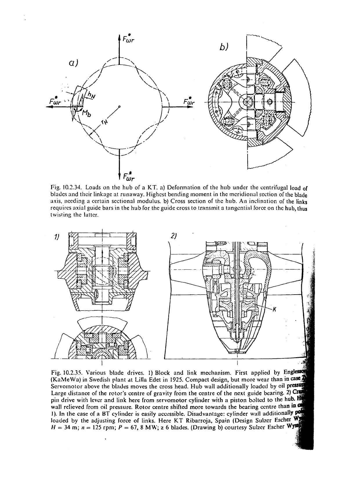
Fig.
10.2.34.
Loads on the hub of
a
KT.
a) Deformation of the hub under the centrifugal load
of
blades and their linkage at runaway. Highest bending moment in thc mcridio~~al section of the blade
axis, needing
a
certain sectional modulus. b) Cross section of thc hub.
An
inclination of the links
requires axial guide bars in the hub for the guide cross to transmit
a
tangential force on the
hub,
thus
twisting the latter.
