Raabe J. Hydro power - the design, use, and function of hydromechanical, hydraulic, and electrical еquipment
Подождите немного. Документ загружается.

$th a pronounced
q
peak at bep, whereas a
KT
especially the double
regulated
one,
b-
afl
atter curve around the bep. Thereby the KT
can
be
adapted better
to
a
changing
&rnand of power. This item must be put aside in
a
plant with a large nurnbcr
of
se~
~~~thermore the
KT
operating with constant speed
can
be
adapted much
better
than
a
FT
to head variations at nearly constant eficiency. Further the runner of
a
FT
witb
n,
'
350 is axially too elastic and is mechanically not suitable for elevated heads,
whereas
a
KT
runner of this n,-range is no problem. Finally the level of bep efidency
of
a
FT
Nnner with highest specific speed n,
2
350 of this type is rather low.
Examples of large and medium FTs in this range of
n,
are shown in
Fig.
10.3.8
and
~jg.
10.3.17.
10.3.4.
Efficiency of
a
F'T
as
a
function of
specific
speed
After a systematic survey carried out on 340 FTs, Zanobetti found the efficiency
at
bep
to
depend as follows on the specific speed n, in the range 145
<
n,
<
340 [10.34]:
For
qopm
see (10.3- 1). Hence for a given head the designer should tend to set
n
and
P,,,
x,
as to obtain n,
=
145. At full load with an efficiency drop
Aq
of about 2% the efficiency
according to Zanobetti [10.34] becomes
Fhlally the same author found the efliciency at 50% of full-load output
Po,,
,,,
to
be
expressed by
'loss
=
op
-
0,0521 (~1,1145
-
-
(10.3-4)
In
the above
qopm
=
0,935 (0,925) and
70,s
,,
=
qopm
-
0,04. The relations demon-
strate clearly that the efficiencies
qop;
ll,,l;
qOs5
decrease when n, increases above
145.
Note
that these values apply to very large units. Hence for
a
FT with
n,
=
420:
qo,
=
0,92;
ql,l
=
0,87;
=
0,72. This figure makes clear the limits of
n,
due to a
FT.
A
rather bad feature of a FT, also occurring on a
KT
with fixed runner vanes, is the
pressure surge in the draft tube, when the machine operates away from the bep (Cap. 5.5,
8.2
and 9.8) and
if
its runner is of the overhung design.
Contrary to a KT the FT has a more moderate submergence in consequence of its
smal!er
cavitation index (see Table 9.2.1).
Also the runaway speed the set has to withstand, which increases with rising n, from
1,4
to 2 times the normal speed, is considerably smal!er for a FT than for a KT. This appears
in
the dangerous case of off-cam operation at low heads up to 3,5 times the normal speed
[8.132].
10.3.5.
The
design of
a
Francis turbine
The design of a
FT
starts from H,
Q
given the topography and the hydrograph. The speed
fl
must be compatible with the grid frequency and the integer number of pole pairs of the
alternator but set,
if
possible, so as to get a specific speed n,
=
145, where
n,
=
"('prn)
(Pill
(kW))'12/H
(m)5'4.
As outlined in Cap.
9.2,
for reasons of limited submergence
and runner strength, a certain n, is assigned to
H,
a relation which corresponds to the
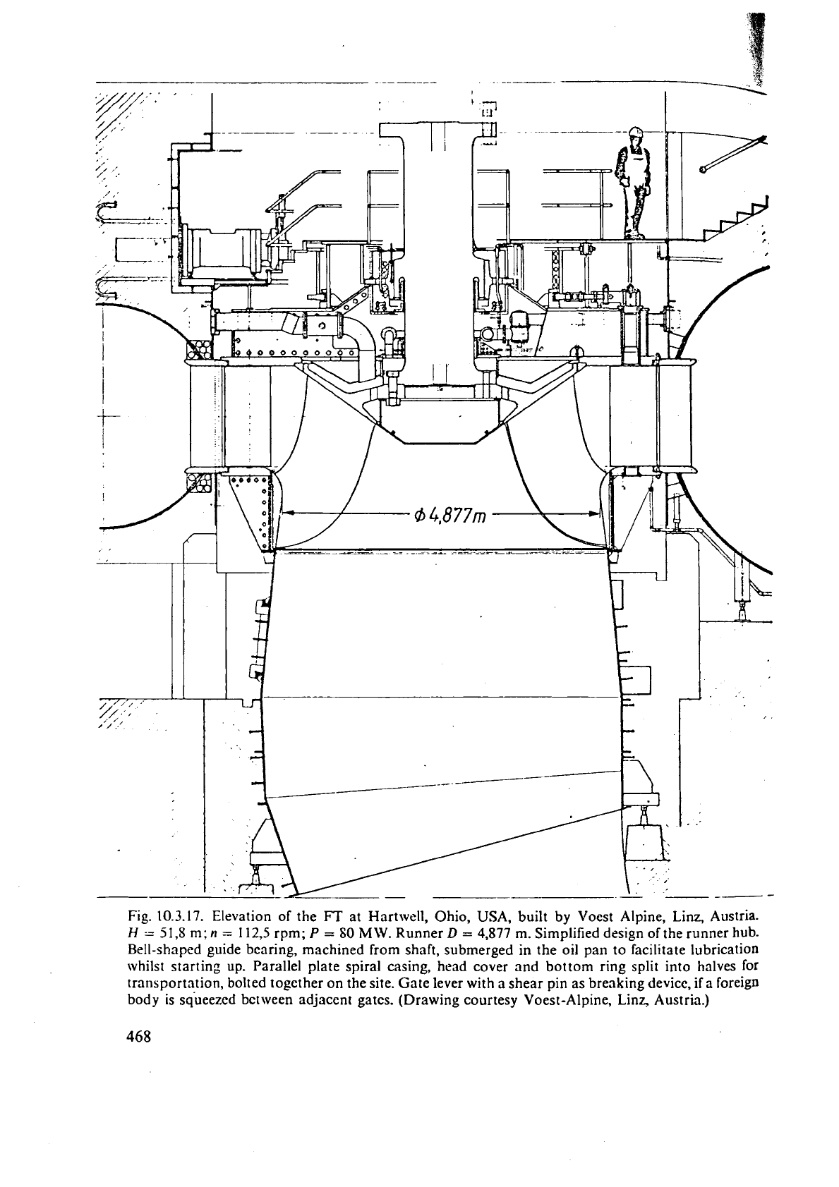
Fig.
10.3.17. Elevation of the
FT
at Hartwell, Ohio,
USA,
built by Voest Alpine, Linz, Austria.
H
.=
51,s
m;
n
=
112,5
rpm;
P
=
SO
MW.
Runner
D
=
4,877
m. Simplified design of the runner hub.
Bell-shaped guide bearing, machined from shaft, submerged in the oil
pan
to facilitate lubrication
whilst starting up. Parallel plate spiral casing, head cover and bottom ring split into halves for
transportation, bolted together on the site. Gate lever with
a
shear pin as breaking device, if a foreign
body is squeezed between adjacent gates. (Drawing courtesy Voest-Alpine,
Lin~ Austria.)
te
of the art, which in the future will move to assign higher
n,(ns)
values to a certain
sf=
wd-
gctdng
ns
above the actual limit for
H,
means firstly higher submergcllcc and hence
aovation cost. Then the runner is more highly stressed, so as to require
a
stronger
wtcrial or to need
a
more careful stress calculntion
(10.521,
e.g., by finite element method
1391.
This holds especially for larger and hence more elastic units as seen in
[lo'
10.3.17
and
10.3.8.
Fig
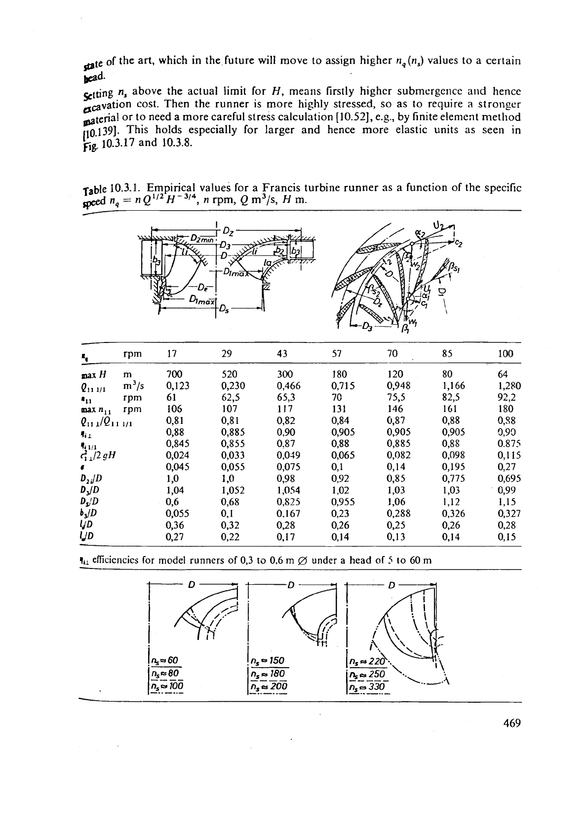
rab1e
10.3.1.
Empirical values for a Francis turbine runner as a function of the specific
n
-~Q~/~H-~/~ n
Ipeed
9-
,
rpm,
Q
m3/s,
H
m.
1.
rpm
17
29 4 3 57 70 85 100
-
mxH
m
700
Qll
111
m3/s
0,123
81
1
rpm
61
maxn,,
rpm
105
QII
JQII
111
0,8
1
li
L
0,88
0,845
2
y2
0,024
#
0,045
D,
ilD
1
,o
DJD
1,04
DS1D
0,6
*dD
0,055
Ii'D
0,36
yo
0,27
qil
efficiencies
for model runners of
0,3
to
0,6
m
0
under
a
head
of
5
to 60
m
For
;I
gibsn spe~ific spced
11,
or
:I,,.
tl~c r,ited unit dischilrgt' Q,,
:lnd
~iilit
speed n,,
nr
obtilincd fl-orn Tablc
10.3.1.
Ilcncc,
rhc
runncr tlirln~ctcr altcrnntivcly (for control)
!\s
;I
third control thc
blade
tip speed coefficient Ka may also bc @ptirnizctl with respect
to
il
n~axiniuin surplus during the useful life of the turbine, following the lincs of Cap.
4
4
-
.
Oiicc ri(rpm) and
=
7t
11/30 arc known, thcn
Y
0nc'c'~ is known aild the figures D2JD, D,/D. bJD, IJD,
li/D,
D,/D are taken
from
Table 10.3.1 as a function of
n,,
the elevation of the runner, inclusive of the gate's outlet
."
edee
C
and draft tube inlet may be plotted, aided
by
the contours of thc runner given in
the
above table as
it
function of
r?,.
(For qlI1
=
0,9:
11,
=
2,97 n,.)
It
must
be
emphasized that the contour is more or less set at will and reflects the
experience of
a
special maker.
In the following some design features
(as
a function of H or n,) may be mentioned, found
in the survey of modern trends in the design of FTs by
de Siervo
and
cle
Leva
[10.33]
n,
=
3470 H-~.~~~,
KU
=
0,323
+
2,2
rt,.
(10.3-7)
*Thc
outer diamtter of the runner outlet edge Dl, follows from the rated output
P,,,
and
a
coefficient usu;~lly referred to as the coefficient of the largest runner outlet diameter
C,,
a
figure Ivhich
for
machines above
i-\
r~,
about
200
corresponds
to
what
is
called the runner
throat
coeficient
Dla
=
Cl (P,~~)~~~. (10.3-8)
This
rule folloivs t!le experience that the flow through a device or machine under
a
certain
head is l;sually dictated by the size of its narrowest passage. C, may
be
!raced to the
similarit::
laws
(Cap.
9.2).
according to which, wit11
D
=
D,,
Dl,
=
Dl,
the speed may be
expressed by
t~
=
C
Ku(D,,'D,)
II'/~/D,
with
C
as
n
dimension-l~nked constant. Elimi-
nating
tz
from this by means of the definition of
n,
=.
n(P,ll)112/H51" gives
C,
=
C
Ku(D,/D,)/(n, H3I4).
(10.3-9)
Since the values
Kli,
n,,
!i
and Dl jD, depend on n,, C, also is
a
function of
n,.
According
ta
Znnob?tti's
review [10.34]
C,
=
0,075
+
O,S55
.
n,. (10.3- 10)
For the output, according to Cap.
9.2:
P
=
PI,
D2 H3I2. Hence by logarithmic differen-
tiation and putting
tlP
=
P
-
PI/,
and
dH
=
H
-
IIlI,:
PIP,,
=
-
0,5
+
1,5 H/HIIl.
Af-
ter
ZanoSrtti
for the machines reviewed
P,'Plll
=
-
0,433
+
1,44 H/Hlil.
(10.3- 11)
The span
of
the gate depends according to
de
Sierro
[10.33] on
11,
as
b,iD,
=
0,188
+
0,5
-
10-3n,.
(10.3-12)
The axial
depth
'a'
of runner (Fig. 10.3.18) as the distance
of
the outmost point on the
runner outlet edge from the distributor's centre line, according to
de Siervo
and
de
Leva,
is given by [10.33]
a/D,
=
-
0,05
+
42/n,,
(50
<
n,
<
110)
a/Dl=1/(3,16-0,0013nS), (110<nS<350).
.
(10.3-
13)
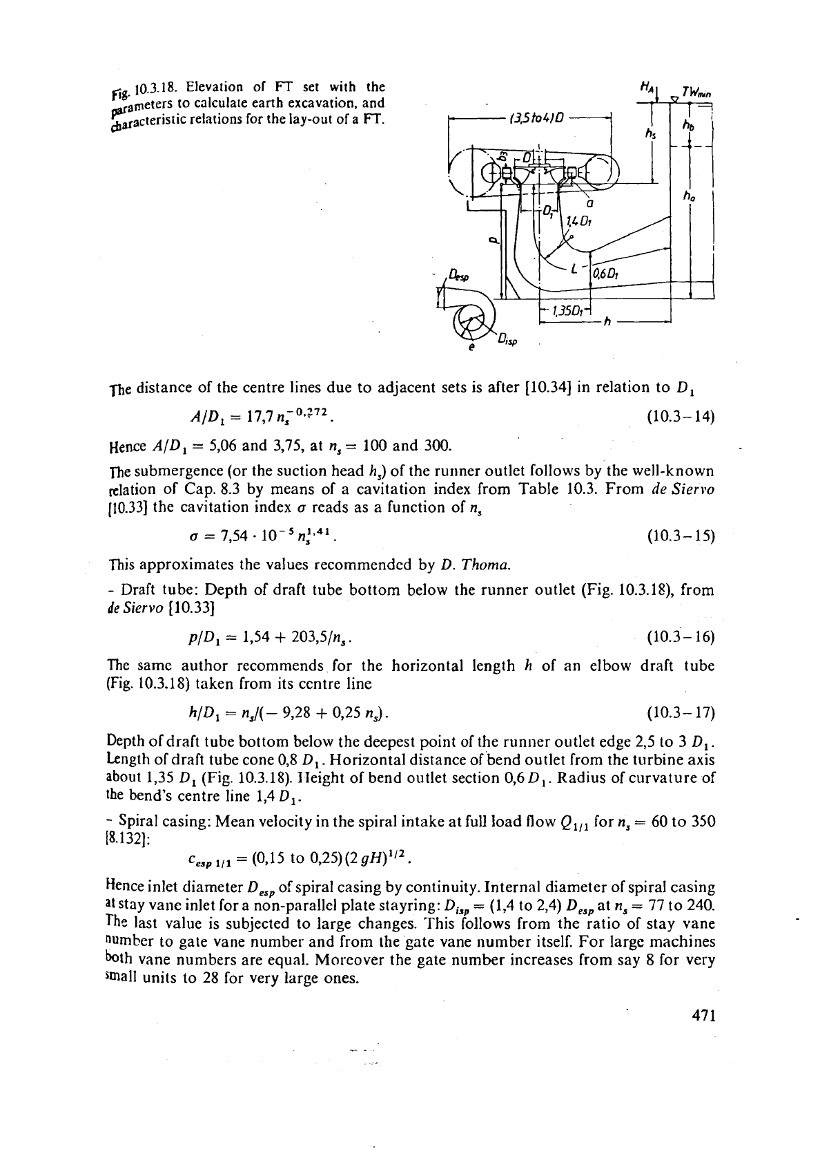
10.3.18.
Elevation of set with the
figimeterr to calculate earth excavation,
and
pa'
cbaracteristi~ relations for the lay-out of a
FT.
fie
distance of the centre lines due to adjacent sets is after
[10.34]
in relation to
Dl
Hence
AID,
=
5,06
and
3,75,
at
n,
=
100
and
300.
The submergence (or the suction head
h,)
of the runner outlet follows by the well-known
nlation of Cap.
8.3
by means of a cavitation index from Table
10.3.
From
de
Siervo
[10.33]
the cavitation index
a
reads as a function of
ns
This approximates the values recommended by
D.
Thoma.
-
Draft tube: Depth of draft tube bottom below the runner outlet (Fig.
10.3.18),
from
de
Siervo
[10.33]
The same author recommends for the horizontal length
h
of an elbow draft tube
(Fig.
10.3.18)
taken from its centre line
hlD,
=
ns/(-
9,28
+
0,25
n,).
(10.3- 17)
Depth
of
draft tube bottom below the deepest point of the runner outlet edge
2,5
to
3
Dl.
Length of draft tube cone
0,8 Dl
.
Horizontal distance of bend outlet from the turbine axis
about
1,35
Dl
(Fig.
10.3.18).
IIeight of bend outlet section
0,6
D,.
Radius of curvature of
the bend's centre line
1,4 Dl.
-
Spiral casing: Mean velocity in the spiral intake at full load flow
Q,,,
for
n,
=
60
to
350
[8.132]:
c,,
,,,
=
(0,15
to
0,25)(2 gH)1'2.
Hence inlet diameter
D,,
of spiral casing by continuity. Internal diameter of spiral casing
at
stay vane inlet for a non-parallel plate stayring:
D,,
=
(1,4
to
2,4)
D,,,
at
n,
=
77
to
240.
The
last value is subjected to large changes. This follows from the ratio of stay vane
number to gate vane number and from the gate vane
lumber
itself. For large machines
both vane numbers are equal. Moreover the gate number increases from say
8
for very
small units to
28
for very large ones.
-
3
1:inally thc dii~metcr is inflncnccd by
the
hct wliet!~cr the spiral
ciising
is
of
tllc
pnralld
pl;ltc
dcsign nficr 1'ig:lct
(Fig.
10.3.4)
13.1281
or the
sl;~ssic:ll
dcsigo (Fig.
10.3.5).
The
latter
is
rno1.e
sp;lce
consuminp.
and
strcsscs the stay va~ics, its crown
;lad
bottom
cover
more
than
in
the first design but
if
offers
a
more smooth intake for the stay vanes.
As
a
gcncral rulc
attention
has to be paid to the strcngth of the spiral, stay vane rings and stay van
CQ,
hcad and bottom cover and distributor vanes under the following rclcv;ult lond9 especially devcl-
oped at closed ptes: Water load ur.dcr test pressure, which is ust~aliy 1,5 times the highest working
prcssu'rc composed of thc static prcssurc plus the highcst adn~issiblc prcssurc surge due to
hammer.
b
Load of the thrust bearing, whcn this is supported by a truncated cone on the head cover. Membrane
stress from the shell of the spiral casing usually calculated so as to assume the top most
quasi
cylindrical section through thc spiral casing wall as free of shear parallel tc the machine axis. Besides
the junction bctwcen spiral casing wall and thc stay vane rings (usually casings) also transfers
bending moments The strength of the stay vane ring is the core of a FT design.
By adopting
Piguet's contracted spiral casing with parallcl platcs of the stay vane ring, the ca1cula.
tion bccomcs more reliable and transparent, since the stay vanes are then of constant span over their
streamwise length, and are attacked more centrally by the membrane pu!l from the spiral casing wall.
'The bending moment in the junction of a spiral casing is a conscquence of t'nc closure of an imaginary
gap that would cxist if the load-induccd deformations of the stay ring and spiral casing were
consitiercd indepcndcnt of each other. This gap would exist alotlg the circular junction of stay ring
and spiral casing. In rcality it is closed mainly by the action of an internal bending moment around
a tangent of this circle. This causes a bending stress in the meridional direction, which has to
be
superimposed on the meridional melnbran stress due to internal pressure of the spiral casing. In a
wclded design, for reasons of fr~brication, this highly btrcssed junction is
implemented
by
a
weld seam.
Manhole and pedestal of the spiral casing, or
the concretc propping it, must not overstress it.
Moreover
thcre are fatigue problems in the spiral casing. the stay rings, and the stay vanes of sets
w!lich often change their mode of operation [10.124 to 10.1311.
The stress calculation of the
gate and its drive in closed position under squeezing adjacent gates
necds ths same care tv~th respect to strength [10.59; 10.89; 10.1221. Here thc "submergence" of the
gate
dribe (see Fips. 10.3.1 or 10.4.17) into the hcad covcr
(if
possible) avoids jamming of the gate stem
by
defor~nation of head cover. enable5 statically dctcrrnined support of thc gates (two bearing
arrangement) and
eliminates
the fatigue problem at the tramition between stem and blade of the
gate.
Thc latter follows from the fact that in a two bcaring arrangement, this section with its strongly
varying
sectiona! modulus is not subjected to axial bendins stresses (acting parallcl to the stem),
ivl~ose flux would there experience a strong contraction connected with notch effects i2.231. However
such a design is restricted to heads below 450
nl (the FTs of Grand Coulee
111
built by Allis Chalmers
can be
considered
to be an exemplary constrt~ction of this type). (See Cap. 2.3.)
The
head cover of huge and high head machines must be stiff so as to avoid deformation causing
fouling of
thc runner within the labyrinths and exciting runner vibrations by variation of the
labyrinth's gap clearance
[8.132].
The circumferential development of the
cross
sectional
area
of
the
spiral
casing tube
follows
from
the intention to distribute the flow to the
runner
uniformly over the circum-
ference, with
an
angular momentum near to that required
by
the runner.
To reduce the
loss in the case of highest heads, usually the angular monlentum within the spiral tube
is smaller
than required
by
the runner. To save space in the case of low-he:~d plants with scmi-spiral
casings, the angular
nlomentum in the duct of the latter is larger than required. Because of the
relatively
smal! kinetic energy in the ducts of the guide apparatus there, this does not influence the
eficiency. At any rate, the change to angular momenturn required is effected by the stay and guide
vanes.
Dimensioning of the
cross
sections
is
based
on
the assumption that at
least
in
the first
three quarters
of
the circumference
a
velocity distribution
is
generated
that
corresponds
to
that of a free vortex. Hence the distance
e
of the outmost spiral wall from the machine
depends as follows on the azimuthal distance
cp
from the radius due to the inlet
section of the spiral case near its tongue: cp(e/D,,) 90"
(13..
.2,5);
180" (1,7.. .2,3);
270"
(1,5
.
.
.1,9); 360" (1,3..
.
1,4).
For
heads below about 30 m also semi-spiral casings are applied. Inlet width:
2,9
-
D.
Eccentricity: related to the axis of the turbine: 0,2
D.
Maximum height: 1,4
-
D.
Maxi-
mum
lateral distance of the spiral chamber wall from the axis: 1,4
-
D,
[10.147].
10.3.6.
Design
of
the
runner
vane, simplified
method
1)
~ivision of the runner vane channel into
i
elementary turbines
(i
=
2
for small
n,,
i
=
5
for
high n,, according to Fig. 10.3.19), having the same flow
AQ
=
Q,,,!i.
QSp
follows from
the
ratio
Qll
.,/Ql1
,,,
in Table 10.3.1. Continuity for an elementary turbine, local span
~b,
local distance from axis
r,
local meridional velocity
c,,
local contraction coefficient
@
(due
to vane and boundary layer), requires
AQ
G=
2nAbrc,@
=
const.
(10.3- 18)
The
procedure is best satisfied along a normal to the preliminarily set meridional
streamlines in the n-direction. Strictly speaking introduction
of
c,
requires knowledge
of
the
c,
distribution, Cap. 10.6 or 6.4.
A
simplified mean value of
c,,
follows from
Fig.
10.3.19.
Elevation
and
plan
of
an
arbitrary
FT
(hcre
with
n,
=
100)
with ch-nentary turbines,
mdial
and pattern sections and angles.
473
c,,
-
Q,,p
!?
ii:
I.,,
h
+),
\Y~L'I-C
I)
is the local brc:ldth of rdtor,
is,,
tile mean 11ist;rnce of this
t~rc:rdt!l Croln
:I\;,.
Tlic~!
(.,,
-
<
c,,,,,f.
hlore rigorously
is
ob~itined from thc potelltial
How
p;i!
tcrn
in
I
he meridt;~n, !:unccl by
thc
~raphical method after Cap.
5.2;
ro~g'illy with
11,
=
60.
.3
10.
on
the 41roucl
<
=
1
.
.
.
1,S
ancl on the hub
5:
-
1
. .
.0,5.
The contraction
cocfiicicn
t
~1)
1nay
bc
prclilr1;narily
estimated
between
0,9
and
0,7.
Strictly speaking
(b
depends on the real vane thickness
It,
the anglc
/I'
between the pilttcrn
making vane sectior, and tl?e periphery, thc angle
O
between the radial vane section and
radius, the r:ttiius
r
and thc vane numbcr
z
:IS
follows
[8.132]
L
(b
=
1
-
[It
2/(2
n
r)]
(1
+
cot /I'/sin2 @)'I2
.
(10.3-
19)
~trictl~ spcilking
It
contains also the displacement thickness of
the
boundary layers
on
both the faces. Ro~~ghly
h
corresponds to the vane thickness resulting from the stress
calculatior! given later on.
In general
the vane nurnber
z
is odd to avoid excitation of torsionai vibratioils at
the
instant the rotor vane cuts
a
wake from the gate, whose number is in general even.
The
numbcr of runner vanes
may
vary from
z
=
7
to 17 for hcads of
20
to 700 m.
,
2)
Ass~~rnption of ttic strca~nwise cl~ange of aiigular mornenturn: After tests on Francis
turbines
by
Uiir
[5.17]
a!ld
Schler)~nzer
[5.18]
(Figs. 10.3.20 and 10.3.21),
earl-ied
out at
Lehrstuhl und Lab~r fiir Flydraulische Maschinen und Anlagen
TU
Miinchen, West
Germany, in a streamwise directio~~ at
a
working point near the bep. the angular momen-
Fig.
10.3.20.
Test results, show-
ing
thc
graph of the'absolute
flow
cnergy
Y,
and rothalpy
Y,,
both related to specific head
gH
vs
unrolled lllcridional stream
i
f
liiw length
s
for various elemen-
tary
tur'oincs of
a
FT
with
n,
=
70
at bep according to
the
hill
diagram. of
Fig.
10.3.21.
B
elementary
turbine close to
the shroud;
F
ditto close to the
hub.
Plccordingly lines
C,
D,
E
belonging to the mean meridi-
onal
streamlines
of
the
elemen-
tary
turbincs from thz shroud lo
the hub. Frorn
E.
Bar:
Messung
des relativen Strijn~ungsfeldes
in
Wasser an der ~aufschaufel
0
eincr schnelliiufigcn Francistut-
o
bine. Forschung Ing. Wesen
36
coordinate
s
(I
970),
no
2.
p.
54/61.
.
1;o
1.2
nll/"llopt
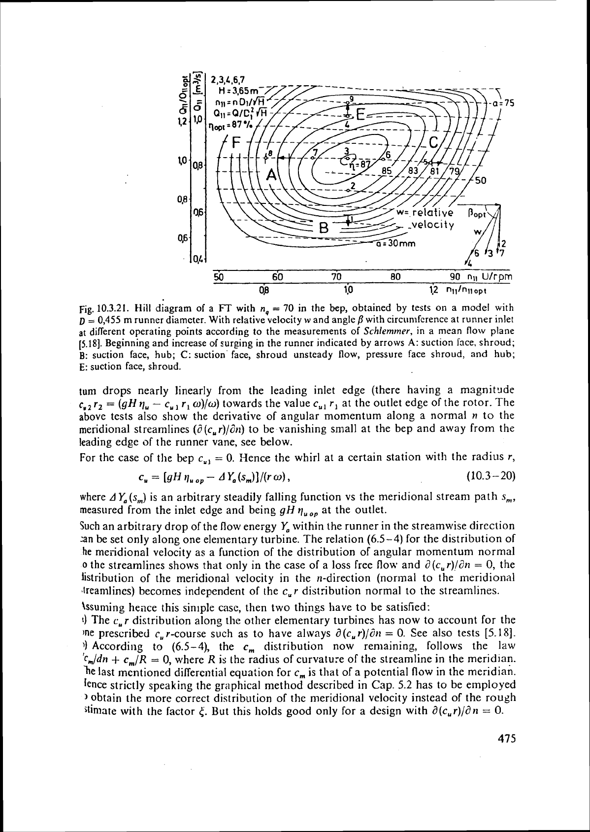
Fig.
10.3.21.
Hill
diagram of a
FT
with
n,
=
70
in the
bep,
obtained
by
tests on a model with
D
=
0,455
m
runner diameter.
With
relative velocity
w
and angle
j3
with
circumference
at runner inlet
at
different operating points according to the measurements of
Schlemmer,
in a mean flow plane
(5.181.
Beginning and increase of surging in the runner indicated by arrows
A:
suction face, shroud;
B:
suction face, hub;
C:
suction' face, shroud unsteady flow, pressure face shroud, and hub;
E:
suction face, shroud.
turn drops nearly linearly from the leading inlet edge (there having a magnit~de
cU2
r2
=
(gH qu
-
c,
rl
o)/o)
towards the value
c,,
r, at the outlet edge of the rotor. The
above tests also show the derivative of angular momentum along a normal
n
to the
meridional streamlines
(d(c,r)/an) to be vanishing small at the bep and away from the
leading edge of the runner vane, see below.
For the case of
the bep
c,,
=
0.
Hence the whirl at a certain station with the radius r,
where AY,(S,~) is an arbitrary steadily falling function vs the meridional stream path s,,
measured from the inlet edge and being gH quo, at the outlet.
Such an arbitrary drop of the flow
energy
Yo
within the runner in the streamwise direction
an be set only along one elementary turbine. The relation (6.5-4) for the distribution of
he
meiidional velocity as a function of the distribution of angular momentum normal
0
the streamlines shows that only in the case of
a
loss free flow and
a
(c,
r)lan
=
0,
the
iistribution of the meridional velocity in the n-direction (normal to the meridional
Jreamlines) becomes independent of the cur distribution normal to the streamlines.
\ssuming heace this sinlple case, then two things have to be satisfied:
1)
The cur distribution along the other elementary turbines has now to account for the
)ne prescribed
c,
r-course such as to have always
d
(c, r)/dil
=
0.
See also tests
[5.18].
))
According
to
(6.5-4), the
c,
distribution now remaining, follows the law
'c,,,/dn
+
cm/R
=
0,
where
R
is the radius of curvature of the streamline in the
meridian.
le last mentioned differential equation for c, is that of
a
potential
flow
in the meridian.
Ience strictly speaking the graphical method described in Cap. 5.2 has to be employed
obtain the more correct distribution of the meridional velocity instead of the rough
$tinlate with the factor
<.
But this holds good only for a dcsign with a(cur)/dn
=
0.
U
I
I
1
I
I
I
15 30
45
SO
75
90
~)5
mm
120
meridional
streampnth
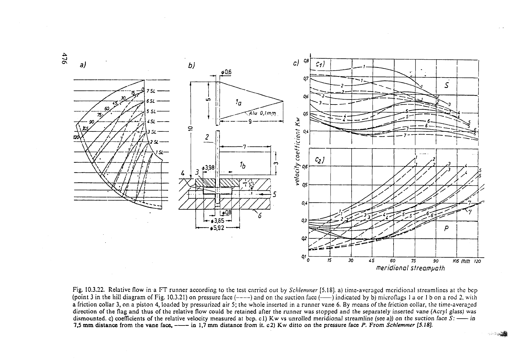
Fig.
10.3.22.
Relative flow
in
a
FT
runner according to the test carried out
by
Schlemnier
(5.181.
a) time-averagcd mcridionnl streamlines
at
the
bcp
(point
3
in the llill diagram of Fig.
10.3.21)
on pressurc face
(----)
and on the suction face
(-)
indicated
by
b) n~icrofl~~gs
I
a
or
I
b on a rod
2,
with
a
friction collar
3,
on a piston
4,
loaded
by
pressurized air
5;
the whole inserted
in
a runncr vane
6.
By
mcans
of
the friction collar, the rime-averazcd
direction of the flag and thus of the relative
flow
could be retained after the runner was stopped and
the
separately inserted vane
(Acryl
glass) was
dismounted. c) coefficients of the relative velocity measured at bcp.
cl)
Kw
vs unrolled meridiomJ streamline (see a)) on thc suction face
S:
-
in
7.5
mm
distance
from the vane face,
---
in
1,7
mm distance from it.
c2)
Kw
ditto
on
the pressure face
P.
From
Schlemmer
15.1
81.
,
