Pumping Station Desing - Second Edition by Robert L. Sanks, George Tchobahoglous, Garr M. Jones
Подождите немного. Документ загружается.

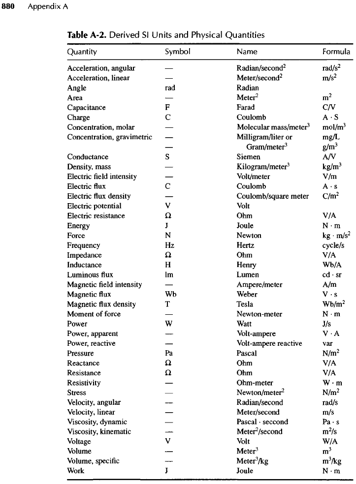
Table
A-2.
Derived
Sl
Units
and
Physical
Quantities
Quantity
Symbol
Name
Formula
Acceleration, angular
—
Radian/second
2
rad/s
2
Acceleration, linear
—
Meter/second
2
m/s
2
Angle
rad
Radian
Area
—
Meter
2
m
2
Capacitance
F
Farad
C/V
Charge
C
Coulomb
A • S
Concentration, molar
—
Molecular
mass/meter
3
mol/m
3
Concentration, gravimetric
—
Milligram/liter
or
mg/L
—
Gram/meter
3
g/m
3
Conductance
S
Siemen
A/V
Density, mass
—
Kilogram/meter
3
kg/m
3
Electric
field
intensity
—
Volt/meter
V/m
Electric
flux C
Coulomb
A • s
Electric
flux
density
—
Coulomb/square meter
C/m
2
Electric potential
V
Volt
Electric resistance
Q.
Ohm V/A
Energy
J
Joule
N • m
Force
N
Newton
kg •
m/s
2
Frequency
Hz
Hertz
cycle/s
Impedance
Q Ohm V/A
Inductance
H
Henry
Wb/A
Luminous
flux
Im
Lumen
cd • sr
Magnetic
field
intensity
—
Ampere/meter
A/m
Magnetic
flux Wb
Weber
V-s
Magnetic
flux
density
T
Tesla
Wb/m
2
Moment
of
force
—
Newton-meter
N • m
Power
W
Watt
J/s
Power, apparent
—
Volt-ampere
V • A
Power, reactive
—
Volt-ampere reactive
var
Pressure
Pa
Pascal
N/m
2
Reactance
Q
Ohm V/A
Resistance
Q Ohm V/A
Resistivity
—
Ohm-meter
W • m
Stress
—
Newton/meter
2
N/m
2
Velocity,
angular
—
Radian/second rad/s
Velocity,
linear
—
Meter/second
m/s
Viscosity,
dynamic
—
Pascal
•
seccond
Pa • s
Viscosity,
kinematic
—
Mete^/second
m
2
/s
Voltage
V
Volt
W/A
Volume
—
Meter
3
m
3
Volume,
specific
—
Mete^/kg
m
3
/kg
Work
J
Joule
N-m
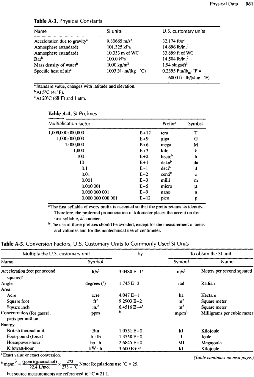
Table A-3.
Physical
Constants
Name
Sl
units U.S. customary units
Acceleration
due to
gravity
3
9.80665
m/s
2
32.174
ft/s
2
Atmosphere (standard)
101.325
kPa
14.696
lb/in.
2
Atmosphere (standard)
10.333
m
of WC
33.899
ft of WC
Bar
b
100.0
kPa
14.504
lb/in.
2
Mass density
of
water
b
1000
kg/m
3
1.94
slugs/ft
3
Specific
heat
of
air
0
1003
N •
m/(kg
•
0
C)
0.2395
Ftu/lb
m
-
0
F
=
6000 ft-HV(SlUg-
0
F)
a
Standard value, changes with latitude
and
elevation.
b
At
5
0
C
(41
0
F).
c
At20°C(68°F)andlatm.
Table A-4.
Sl
Prefixes
Multiplication
factor
Prefix
3
Symbol
1,000,000,000,000
E+12
tera
T
1,000,000,000
E+9
giga
G
1,000,000
E+6
mega
M
1,000
E+3
kilo
k
100 E+2
hecto
b
h
10
E+l
deka
b
da
0.1
E-I
deci
b
d
0.01
E-2
centi
b
c
0.001
E-3
milli
m
0.000001
E-6
micro
u,
0.000000001
E-9
nano
n
0.000000000001
E-12
pico
p
a
The
first
syllable
of
every
prefix
is
accented
so
that
the
prefix retains
its
identity.
Therefore,
the
preferred pronunciation
of
kilometer places
the
accent
on the
first
syllable,
fo'-lometer.
b
The
use of
these prefixes should
be
avoided, except
for the
measurement
of
areas
and
volumes
and for the
nontechnical
use of
centimeter.
Table A-5.
Conversion
Factors,
U.S.
Customary
Units
to
Commonly
Used
Sl
Units
Multiply
the
U.S. customary unit
by To
obtain
the Sl
unit
Name Symbol Symbol Name
Acceleration feet
per
second
ft/s
2
3.0480
E-l
a
m/s
2
Meters
per
second squared
squared
a
Angle degrees
(°)
1.745
E-2 rad
Radian
Area
Acre acre
4.047
E-I
ha
Hectare
Square
foot
ft
2
9.2903
E-2
m
2
Square meter
Square inch
in.
2
6.4516
E-4
a
m
2
Square meter
Concentration
(for
gases),
ppm
b
mg/m
3
Milligrams
per
cubic meter
parts
per
million
Energy
British
thermal
unit
Btu
1.0551
E+0
kJ
Kilojoule
Foot-pound
(force)
ft •
Ib
1.3558
E+0 J
Joule
Horsepower-hour
hp • h
2.6845
E+0 MJ
Megajoule
Kilowatt-hour
kW
•
h
3.600
E+3
a
kJ
Kilojoule
"Exact
value
or
exact
conversion.
№
^
continues
on
next
page.)
b
mg/m
3
=
(PPm)(^aTnSMoI)
x
_27^_
^.
Regulations
use
-
c
=
25?
but
source measurements
are
referenced
to
0
C
=
21.1.
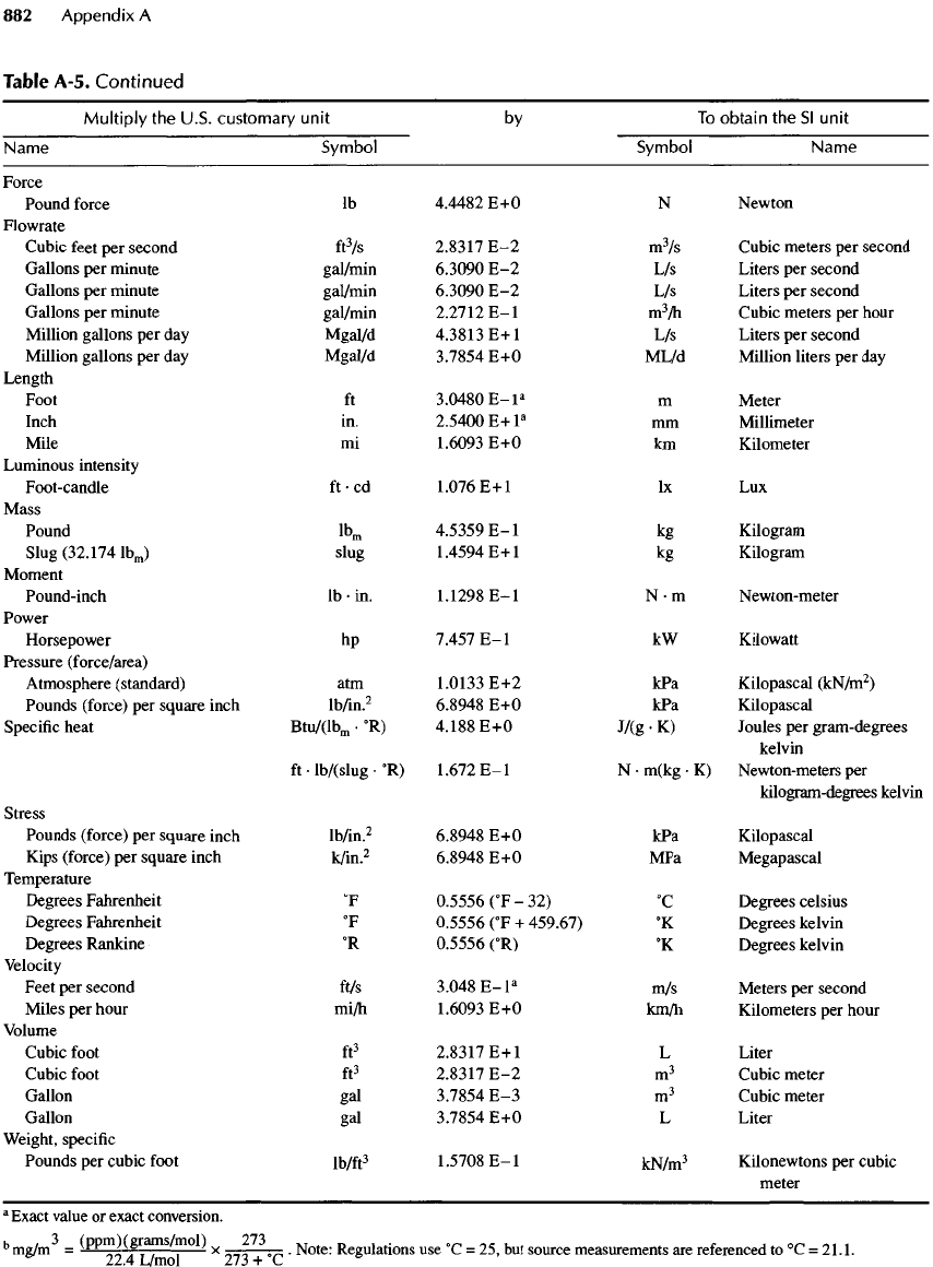
Table A-5.
Continued
Multiply
the
U.S.
customary
unit
by To
obtain
the Sl
unit
Name
Symbol Symbol Name
Force
Pound
force
Ib
4.4482
E+0
N
Newton
Flowrate
Cubic feet
per
second
ft
3
/s
2.8317
E-2
m
3
/s
Cubic meters
per
second
Gallons
per
minute
gal/min
6.3090
E-2 L/s
Liters
per
second
Gallons
per
minute gal/min
6.3090
E-2 L/s
Liters
per
second
Gallons
per
minute gal/min
2.2712
E-I
m
3
/h
Cubic meters
per
hour
Million gallons
per day
Mgal/d
4.3813
E+1
L/s
Liters
per
second
Million
gallons
per day
Mgal/d
3.7854
E+0
ML/d
Million liters
per day
Length
Foot
ft
3.0480
E-l
a
m
Meter
Inch
in.
2.5400
E+l
a
mm
Millimeter
Mile
mi
1.6093
E+0 km
Kilometer
Luminous
intensity
Foot-candle
ft • cd
1.076E+1
Ix
Lux
Mass
Pound
Ib
1n
4.5359
E-I
kg
Kilogram
Slug
(32.174
IbJ
slug
1.4594
E+1
kg
Kilogram
Moment
Pound-inch
Ib
• in.
1.1298
E-I
N • m
Newton-meter
Power
Horsepower
hp
7.457
E-I
kW
Kilowatt
Pressure (force/area)
Atmosphere
(standard)
atm
1.0133
E+2
kPa
Kilopascal
(kN/m
2
)
Pounds (force)
per
square inch
lb/in.
2
6.8948
E+0 kPa
Kilopascal
Specific
heat
Btu/(lb
m
-
0
R)
4.188
E+0
J/(g
•
K)
Joules
per
gram-degrees
kelvin
ft
•
lb/(slug
•
0
R)
1.672
E-I
N-
m(kg
• K)
Newton-meters
per
kilogram-degrees kelvin
Stress
Pounds (force)
per
square inch
lb/in.
2
6.8948
E+0 kPa
Kilopascal
Kips
(force)
per
square inch
k/in.
2
6.8948
E+0 MPa
Megapascal
Temperature
Degrees Fahrenheit
0
F
0.5556
(
0
F
- 32)
0
C
Degrees
Celsius
Degrees Fahrenheit
0
F
0.5556
(
0
F
+
459.67)
0
K
Degrees kelvin
Degrees
Rankine
0
R
0.5556
(
0
R)
0
K
Degrees kelvin
Velocity
Feet
per
second
ft/s
3.048
E-l
a
m/s
Meters
per
second
Miles
per
hour
mi/h
1.6093
E+0
km/h
Kilometers
per
hour
Volume
Cubic
foot
ft
3
2.8317
E+1
L
Liter
Cubic
foot
ft
3
2.8317
E-2
m
3
Cubic meter
Gallon
gal
3.7854
E-3
m
3
Cubic meter
Gallon
gal
3.7854
E+0 L
Liter
Weight,
specific
Pounds
per
cubic
foot
lb/ft
3
1.5708
E-I
kN/m
3
Kilonewtons
per
cubic
meter
a
Exact
value
or
exact
conversion.
b
mg/m
3
=
(PPm)(grams/mol)
x
273
Note
.
R
lations
use
O
G
=
^
but
SQurce
measurements
^
6
referenced
to
0
C
=
21.1.
22.4
L/mol
273 + C
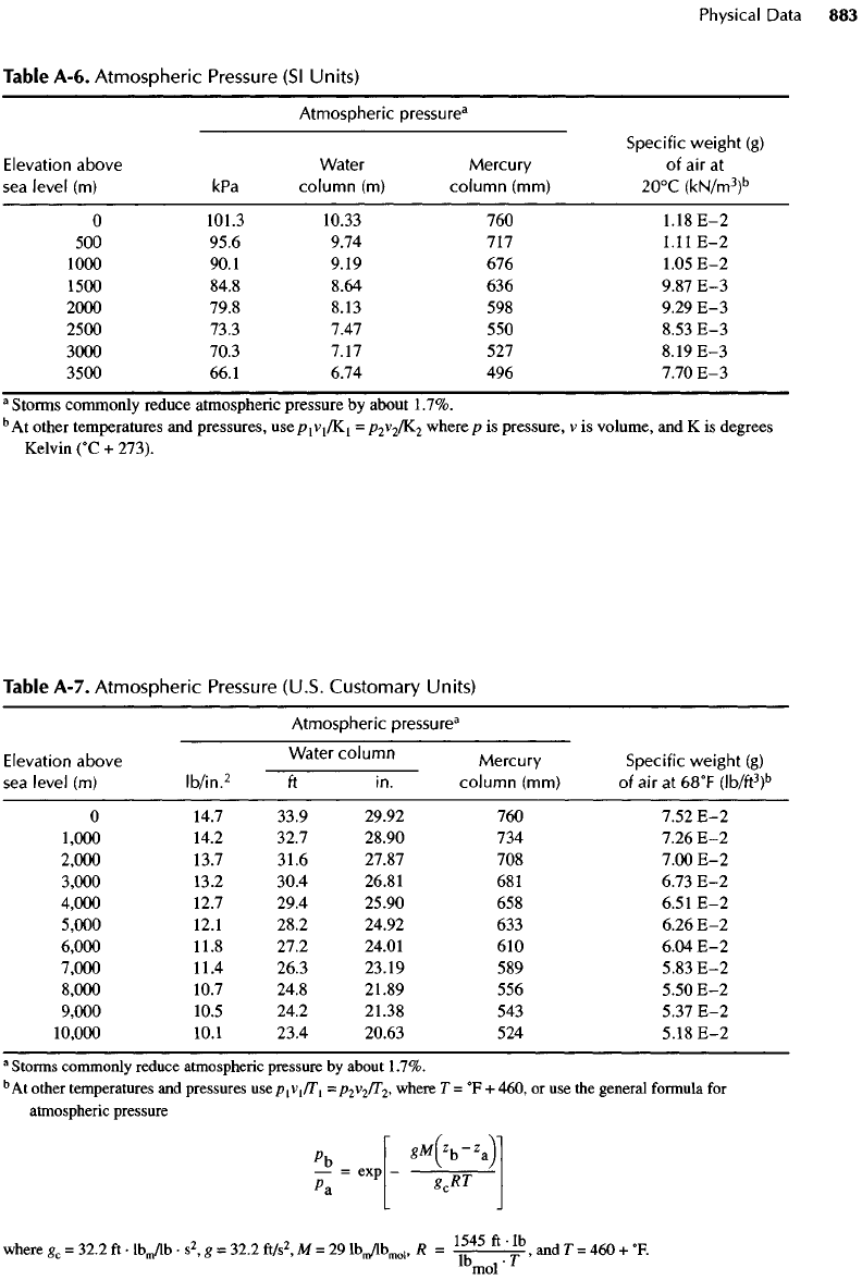
Table
A-6.
Atmospheric
Pressure
(Sl
Units)
Atmospheric
pressure
3
Specific
weight
(g)
Elevation
above Water Mercury
of
air
at
sea
level
(m) kPa
column
(m)
column (mm)
2O
0
C
(kN/m
3
)
b
O
101.3 10.33
760
1.18E-2
500
95.6 9.74
717
1.11E-2
1000
90.1 9.19
676
1.05E-2
1500
84.8 8.64
636
9.87
E-3
2000
79.8 8.13
598
9.29
E-3
2500
73.3 7.47
550
8.53
E-3
3000
70.3 7.17
527
8.19
E-3
3500
66.1 6.74
496
7.70
E-3
a
Storms commonly
reduce
atmospheric
pressure
by
about
1.7%.
5
At
other temperatures
and
pressures,
use
^
1
V
1
TK
1
=
P
2
V
2
I^
2
where
p is
pressure,
v is
volume,
and K is
degrees
Kelvin
(
0
C
+
273).
Table
A-7.
Atmospheric
Pressure
(U.S.
Customary
Units)
Atmospheric
pressure
3
Elevation
above Water
column
Mercury Specific
weight
(g)
sea
level
(m)
Ib/in.
2
ft in.
column
(mm)
of air at
68
0
F
(Ib/ft
3
)
b
O
14.7 33.9
29.92
760
7.52
E-2
1,000
14.2 32.7
28.90
734
7.26
E-2
2,000
13.7 31.6
27.87
708
7.00
E-2
3,000
13.2 30.4 26.81
681
6.73
E-2
4,000
12.7 29.4
25.90
658
6.51
E-2
5,000
12.1 28.2
24.92
633
6.26
E-2
6,000
11.8 27.2 24.01
610
6.04
E-2
7,000
11.4 26.3 23.19
589
5.83
E-2
8,000
10.7 24.8 21.89
556
5.50
E-2
9,000
10.5 24.2 21.38
543
5.37
E-2
10,000
10.1 23.4
20.63
524
5.18
E-2
a
Storms commonly reduce atmospheric pressure
by
about
1.7%.
b
At
other temperatures
and
pressures
use
P
1
V
1
TT
1
=
p
2
v
2
/T
2
,
where
T =
0
F
+
460,
or use the
general
formula
for
atmospheric
pressure
p
b
\
**(*!,-'.)'
U
-
ex
>
-
-&T-
where
g
c
=
32.2
ft •
lb
m
/lb
• s
2
, g =
32.2
ft/s
2
,
M = 29
lb
m
/lb
mol
,
R =
1
^
45
ft
'
*
b
,
and
T =
460
+
0
F.
lb
mol'
l
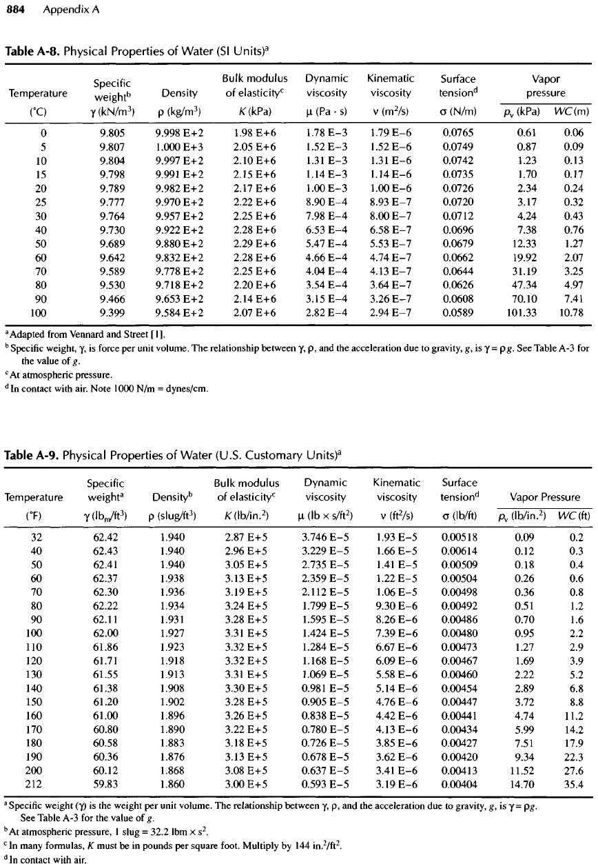
Temperature
(
0
C)
O
5
10
15
20
25
30
40
50
60
70
80
90
100
Specific
weight
6
y
(kN/m
3
)
9.805
9.807
9.804
9.798
9.789
9.777
9.764
9.730
9.689
9.642
9.589
9.530
9.466
9.399
Density
p
(kg/m
3
)
9.998
E+2
1.000
E+3
9.997
E+2
9.991
E+2
9.982
E+2
9.970
E+2
9.957
E+2
9.922
E+2
9.880
E+2
9.832
E+2
9.778
E+2
9.718
E+2
9.653
E+2
9.584
E+2
Bulk
modulus
of
elasticity
0
K(UPa)
1.98
E+6
2.05
E+6
2.10
E+6
2.15
E+6
2.17
E+6
2.22
E+6
2.25
E+6
2.28
E+6
2.29
E+6
2.28
E+6
2.25
E+6
2.20
E+6
2.14
E+6
2.07
E+6
Dynamic
viscosity
p.
(Pa • s)
1.78E-3
1.52
E-3
1.31
E-3
1.14
E-3
1.00
E-3
8.90
E-4
7.98
E-4
6.53
E-4
5.47
E-4
4.66
E-4
4.04
E-4
3.54
E-4
3.15
E-4
2.82
E-4
Kinematic
viscosity
v
(m
2
/s)
1.79E-6
1.52
E-6
1.31
E-6
1.14
E-6
1.00
E-6
8.93
E-7
8.00
E-7
6.58
E-7
5.53
E-7
4.74
E-7
4.13
E-7
3.64
E-7
3.26
E-7
2.94
E-7
Surface
tension
d
o
(N/m)
0.0765
0.0749
0.0742
0.0735
0.0726
0.0720
0.0712
0.0696
0.0679
0.0662
0.0644
0.0626
0.0608
0.0589
Vapor
pressure
p
v
(kPa)
VVC
(m)
0.61
0.06
0.87
0.09
1.23
0.13
1.70
0.17
2.34
0.24
3.17
0.32
4.24
0.43
7.38
0.76
12.33
1.27
19.92
2.07
31.19
3.25
47.34 4.97
70.10
7.41
101.33 10.78
Table A-8. Physical Properties
of
Water
(Sl
Units)
3
a
Adapted
from
Vennard
and
Street
[I].
b
Specific weight,
y, is
force
per
unit volume.
The
relationship between
y, p, and the
acceleration
due to
gravity,
g, is y =
pg.
See
Table
A-3 for
the
value
of g.
c
At
atmospheric pressure.
d
In
contact with
air.
Note
1000
N/m
=
dynes/cm.
Table A-9. Physical Properties
of
Water
(U.S. Customary
Units)
3
a
Specific
weight
(y)
is the
weight
per
unit volume.
The
relationship between
y,
p, and the
acceleration
due to
gravity,
g, is y = pg.
See
Table
A-3 for the
value
of g.
b
At
atmospheric pressure,
1
slug
=
32.2
lbm
x s
2
.
c
In
many formulas,
K
must
be in
pounds
per
square foot. Multiply
by 144
in.
2
/ft
2
.
d
In
contact with
air.
Temperature
(
0
F)
32
40
50
60
70
80
90
100
110
120
130
140
150
160
170
180
190
200
212
Specific
weight
3
Y(IbJfI
3
)
62.42
62.43
62.41
62.37
62.30
62.22
62.11
62.00
61.86
61.71
61.55
61.38
61.20
61.00
60.80
60.58
60.36
60.12
59.83
Density
6
P
(slug/ft
3
)
1.940
.940
.940
.938
.936
.934
.931
.927
.923
.918
.913
.908
.902
.896
.890
.883
.876
.868
.860
Bulk
modulus
of
elasticity
0
/C(lb/in.
2
)
2.87
E+5
2.96
E+5
3.05
E+5
3.13
E+5
3.19
E+5
3.24
E+5
3.28
E+5
3.31
E+5
3.32
E+5
3.32
E+5
3.31
E+5
3.30
E+5
3.28
E+5
3.26
E+5
3.22
E+5
3.18
E+5
3.13
E+5
3.08
E+5
3.00
E+5
Dynamic
viscosity
M-
(Ib x
s/ft
2
)
3.746
E-5
3.229
E-5
2.735
E-5
2.359
E-5
2.112
E-5
1.799
E-5
1.595
E-5
1.424
E-5
1.284
E-5
1.168
E-5
1.069
E-5
0.981
E-5
0.905
E-5
0.838
E-5
0.780
E-5
0.726
E-5
0.678
E-5
0.637
E-5
0.593
E-5
Kinematic
viscosity
V
(ft
2
/S)
1.93
E-5
1.66
E-5
1.41
E-5
1.22
E-5
1.06
E-5
9.30
E-6
8.26
E-6
7.39
E-6
6.67
E-6
6.09
E-6
5.58
E-6
5.14
E-6
4.76
E-6
4.42
E-6
4.13
E-6
3.85
E-6
3.62
E-6
3.41
E-6
3.19
E-6
Surface
tension
d
o
(Ib/ft)
0.00518
0.00614
0.00509
0.00504
0.00498
0.00492
0.00486
0.00480
0.00473
0.00467
0.00460
0.00454
0.00447
0.00441
0.00434
0.00427
0.00420
0.00413
0.00404
Vapor
Pressure
p
v
(lb/in.
2
)
WC
(ft)
0.09
0.2
0.12
0.3
0.18
0.4
0.26
0.6
0.36
0.8
0.51
1.2
0.70
1.6
0.95
2.2
1.27
2.9
1.69
3.9
2.22
5.2
2.89
6.8
3.72
8.8
4.74
11.2
5.99
14.2
7.51
17.9
9.34
22.3
11.52
27.6
14.70
35.4
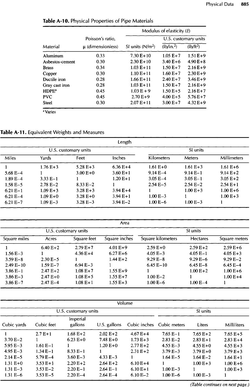
Table
A-10.
Physical
Properties
of
Pipe
Materials
Modulus
of
elasticity
(E)
Poisson's
ratio,
U.S. customary units
Material
n
(dimensionless)
Sl
units
(N/m
2
)
(Ib/in.
2
)
(Ib/ft
2
)
Aluminum
0.33
7.30
E+10
1.05
E+7
1.51
E+9
Asbestos-cement
0.30
2.30
E+10
3.40
E+6
4.90E+8
Brass
0.34
1.03
E+ll
1.50E+7
2.16E+9
Copper
0.30
1.10
E+ll
1.60
E+7
2.30E+9
Ductile
iron
0.28
1.66
E+ll
2.40
E+7
3.46E+9
Gray
cast
iron
0.28
1.03
E+ll
1.50
E+7
2.16E+9
HDPE
a
0.45
1.03
E
+9
1.50
E+5
2.16E+7
PVC
0.45
2.70
E+9
4.00
E+5
5.76E+7
Steel
0.30
2.07
E+ll
3.00
E+7
4.32E+9
a
Varies
Table
A-11.
Equivalent
Weights
and
Measures
Length
U.S. customary units
Sl
units
Miles
Yards
Feet
Inches Kilometers Meters
Millimeters
1
1.76
E+3
5.28
E+3
6.36
E+4
1.61
E+0
1.61
E+3
1.61
E+6
5.68
E-4 1
3.00
E+0
3.60
E+l
9.14
E-4
9.14
E-I
9.14
E+2
1.89
E-4
3.33
E-I
1
1.20
E+l
3.05
E-4
3.05
E-I
3.05
E+2
1.58
E-5
2.78
E-2
8.33
E-2 1
2.54
E-5
2.54
E-2
2.54
E+l
6.21
E-I
1.09
E+3
3.28
E+3
3.94
E+4 1
1.00
E+3
1.00
E+6
6.21
E-4
1.09
E+0
3.28
E+0
3.94
E+l
1.00
E-3 1
1.00
E+3
6.21
E-7
1.09
E-3
3.28
E-3
3.94
E-2
1.00
E-6
1.00
E-3 1
Area
U.S.
customary units
Sl
units
Square
miles Acres Square feet Square inches Square kilometers Hectares Square meters
1
6.40
E+2
2.79
E+7
4.01
E+9
2.59
E+0
2.59
E+2
2.59
E+6
1.56
E-3 1
4.36
E+4
6.27
E+6
4.05
E-3
4.05
E-I
4.05
E+3
3.59
E-8
2.30
E-5 1
1.44
E+2
9.29
E-8
9.29
E-6
9.29
E-2
2.49
E-10
1.59
E-7
6.94
E-3 1
6.45
E-IO
6.45
E-8
6.45
E-4
3.86
E-I
2.47
E+2
1.08
E+7
1.55
E+9 1
1.00
E+2
1.00
E+6
3.86
E-3
2.47
E+0
1.08
E+5
1.55
E+7
1.00
E-2 1
1.00
E+4
3.86
E-7
2Al
E-4
1.08
E+l
1.55
E+3
1.00
E-6
1.00
E-4 1
Volume
U.S.
customary units
SI
units
Imperial
Cubic yards Cubic feet gallons U.S. gallons Cubic inches Cubic meters Liters
Milliliters
1
2.7
E+l
1.68
E+2
2.02
E+2
4.67
E+4
7.65
E-I
7.65
E+2
7.65
E+5
3.70
E-2 1
6.23
E+0
7.48
E+0
1.73
E+3
2.83
E-2
2.83
E+l
2.83
E+4
5.95
E-3
1.61
E-I
1
1.20
E+0
2.77
E+2
4.55
E-3
4.55
E+0
4.55
E+3
4.95
E-3
1.34
E-I
8.33
E-I
1
2.31
E+2
3.79
E-3
3.79
E+0
3.79
E+3
2.14
E-5
5.79
E-4
3.60
E-3
4.33
E-3 1
1.64
E-5
1.64
E-2
1.64
E+l
1.31
E+0
3.53
E+l
2.20
E+2
2.64
E+2
6.10
E+4 1
1.00
E+3
1.00
E+6
1.31
E-3
3.53
E-2
2.20
E-I
2.64
E-I
6.10
E+l
1.00
E-3 1
1.00
E+3
1.31
E-6
3.53
E-5
2.20
E-4
2.64
E-4
6.10
E-2
1.00
E-6
1.00
E-3 1
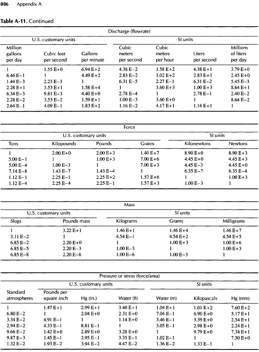
Table
A-11.
Continued
Discharge (flowrate)
U.S.
customary units
Sl
units
Million
Cubic
Cubic
Millions
gallons
Cubic
feet
Gallons
meters meters
Liters
of
liters
per
day per
second
per
minute
per
second
per
hour
per
second
per day
1
1.55
E+0
6.94
E+2
4.38
E-2
1.58
E+2
4.38
E+1
3.79
E+0
6.46
E-I
1
4.49
E+2
2.83
E-2
1.02
E+2
2.83
E+l
2.45
E+0
1.44
E-3
2.23
E-3 1
6.31
E-5
2.27
E-I
6.31
E-2
5.45
E-3
2.28
E+l
3.53
E+l
1.58
E+4 1
3.60
E+3
1.00
E+3
8.64
E+l
6.34
E-3
9.81
E-3
4.40
E+0
2.78
E-4 1
2.78
E-I
2.40
E-2
2.28
E-2
3.53
E-2
1.59
E+l
1.00
E-3
3.60
E+0 1
8.64
E-2
2.64
E-I
4.09
E-I
1.83
E+2
1.16
E-2
4.17
E+l
1.16
E+l 1
Force
U.S.
customary units
Sl
units
Tons
Kilopounds Pounds
Grains
Kilonewtons Newtons
1
2.00
E+0
2.00
E+3
1.40
E+7
8.90
E+0
8.90
E+3
5.00
E-I
1
1.00E+3
7.00E+6
4.45
E+0
4.45
E+3
5.00
E-4
1.00
E-3 1
7.00
E+3
4.45
E-3
4.45
E+0
7.14
E-8
I
A3
E-I
1.43
E-4 1
6.35
E-7
6.35
E-4
1.12
E-I
2.25
E-I
2.25
E+2
1.57
E+6 1
1.00
E+3
1.12
E-4
2.25
E-4
2.25
E-I
1.57
E+3
1.00
E-3 1
Mass
U.S.
customary units
Sl
units
Slugs
Pounds
mass
Kilograms Grams
Milligrams
1
3.22
E+l
1.46
E+l
1.46
E+4
1.46
E+7
3.11
E-2 1
4.54
E-I
4.54
E+2
4.54
E+5
6.85
E-2
2.20
E+0 1
1.00
E+3
1.00
E+6
6.85
E-5
2.20
E-3
1.00
E-3 1
1.00
E+3
6.85
E-8
2.20
E-6
1.00
E-6
1.00
E-3 1
Pressure
or
stress
(force/area)
U.S.
customary units
Sl
units
Standard
Pounds
per
atmospheres
square inch
Hg
(in.)
Water
(ft)
Water
(m)
Kilopascals
Hg
(mm)
1
1.47
E+l
2.99
E+1
3.40
E+l
1.04
E+l
1.01
E+2
7.60
E+2
6.80
E-2 1
2.04
E+0
2.31
E+0
7.04
E-I
6.90
E+0
5.17
E+l
3.34
E-2
4.91
E-I
1
1.14
E+0
3.46
E-I
3.39
E+0
2.54
E+l
2.94
E-2
4.33
E-I
8.81
E-I
1
3.05
E-I
2.98
E+0
2.24
E+l
9.66
E-2
1.42
E+0
2.89
E+0
3.28
E+0 1
9.79
E+0
7.34
E+l
9.87
E-3
1.45
E-I
2.95
E-I
3.35
E-I
1.02
E-I
1
7.50
E+0
1.32
E-2
1.93
E-2
3.94
E-2
4.47
E-2
1.36
E-2
1.33
E-I
1
Power
U.S.
customary units
Sl
units
British
thermal units Foot-pounds Foot-pounds
per
second Horsepower
per
second
per
minute
Kilowatts
1
1.41
E+0
7.78
E+2
4.67
E+4
1.06
E+0
7.07
E-I
1
5.50
E+2
3.30
E+4
7.46
E-I
1.29
E-3
1.82
E-3 1
6.00
E+l
1.36
E-3
2.14E-5
3.03
E-5
1.67E-2
1
2.26
E-5
9.48
E-I
1.34
E+0
7.38
E+2
4.43
E+4 1
Energy
U.S.
customary units
Sl
units
British
Horsepower-hours
thermal units Foot-pounds Kilowatt-hours
Joules
1
2.54
E+3
1.98
E+6
7.46
E-I
2.68
E+6
3.93
E-4 1
7.78
E+2
2.93
E-4
1.05
E+3
5.05
E-7
1.29
E-3 1
3.77
E-7
1.36
E+0
1.34
E+0
3.41
E+3
2.66
E+6 1
3.60
E+6
3.73
E-7
9.48
E-4
7.38
E-I
2.78
E-7 1
A-1.
References
1.
Vennard,
J.
K.,
and R. L.
Street.
Elementary
Fluid
Mechanics,
5th ed.
John
Wiley,
New
York
(1975).
2.
Metcalf
&
Eddy,
Inc.
Wastewater
Engineering,
Treatment,
Disposal,
and
Reuse,
3rd ed.
Revised
by G.
Tchobanoglous.
McGraw-Hill,
New
York
(1991).
Appendix
B
Data
for
Flow
in
Pipes,
Fittings,
and
Valves
ROBERT
L.
SANKS
CONTRIBUTORS
William
F. H.
Gros
Charles
D.
Morris
William
Wheeler
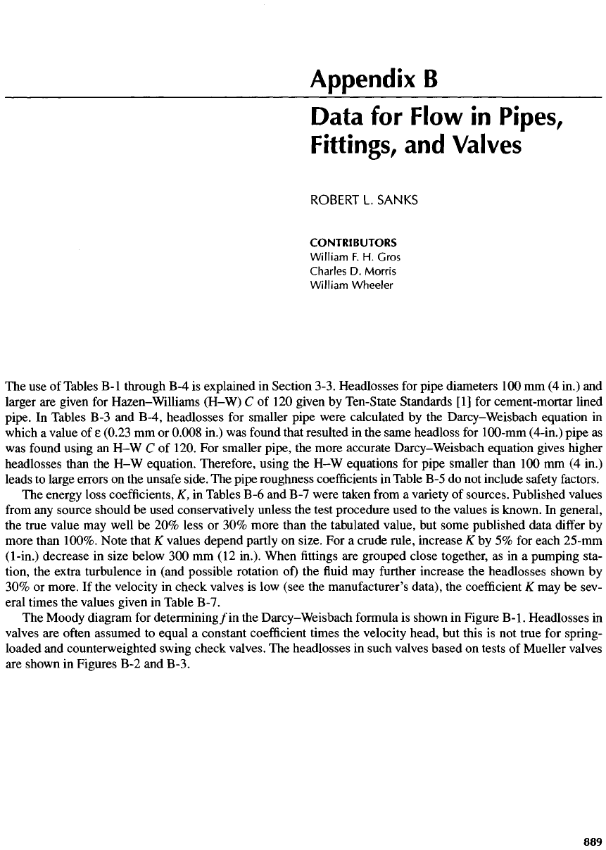
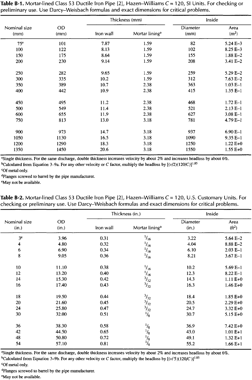
The use of
Tables
B-I
through
B-4 is
explained
in
Section 3-3. Headlosses
for
pipe diameters
100 mm (4
in.)
and
larger
are
given
for
Hazen-Williams
(H-W)
C of 120
given
by
Ten-State Standards
[1] for
cement-mortar lined
pipe.
In
Tables
B-3 and
B-4,
headlosses
for
smaller pipe were calculated
by the
Darcy-Weisbach
equation
in
which
a
value
of e
(0.23
mm or
0.008
in.)
was
found
that resulted
in the
same headloss
for
100-mm
(4-in.)
pipe
as
was
found
using
an H-W C of
120.
For
smaller pipe,
the
more accurate
Darcy-Weisbach
equation gives higher
headlosses than
the H-W
equation. Therefore, using
the H-W
equations
for
pipe smaller than
100 mm (4
in.)
leads
to
large errors
on the
unsafe
side.
The
pipe roughness
coefficients
in
Table
B-5
do not
include
safety
factors.
The
energy loss
coefficients,
K, in
Tables
B-6
and
B-7
were taken
from
a
variety
of
sources. Published values
from
any
source should
be
used conservatively unless
the
test procedure used
to the
values
is
known.
In
general,
the
true value
may
well
be 20%
less
or 30%
more than
the
tabulated value,
but
some published data
differ
by
more than
100%.
Note that
K
values depend partly
on
size.
For a
crude rule,
increase
K by 5% for
each
25-mm
(1-in.)
decrease
in
size below
300 mm (12
in.).
When
fittings are
grouped close together,
as in a
pumping sta-
tion,
the
extra turbulence
in
(and possible rotation
of) the fluid may
further
increase
the
headlosses shown
by
30%
or
more.
If the
velocity
in
check valves
is low
(see
the
manufacturer's data),
the
coefficient
K may be
sev-
eral times
the
values given
in
Table
B-7.
The
Moody diagram
for
determining/in
the
Darcy-Weisbach
formula
is
shown
in
Figure
B-I.
Headlosses
in
valves
are
often
assumed
to
equal
a
constant
coefficient
times
the
velocity head,
but
this
is not
true
for
spring-
loaded
and
counterweighted
swing check valves.
The
headlosses
in
such valves based
on
tests
of
Mueller valves
are
shown
in
Figures
B-2
and
B-3.
Table
B-I.
Mortar-lined
Class
53
Ductile
Iron
Pipe [2],
Hazen-WilliamsC
=
120,
Sl
Units.
For
checking
or
preliminary use.
Use
D
a
rcy-We
is
bach formulas
and
exact dimensions
for
critical problems.
Thickness
(mm)
Inside
Nominal
size
OD
Diameter Area
(mm)
(mm)
Iron
wall
Mortar
lining
3
(mm) (m
2
)
75
e
101
7.87 1.59
82
5.24
E-3
100
122
8.13 1.59
102
8.25
E-3
150
175
8.64 1.59
155
1.88
E-2
200
230
9.14 1.59
208
3.41
E-2
250
282
9.65 1.59
259
5.29
E-2
300 335
10.2 1.59
312
7.63
E-2
350
389
10.7 2.38
363
1.03
E-I
400
442
10.9 2.38
415
1.35
E-I
450
495
11.2 2.38
468
1.72
E-I
500
549
11.4 2.38
521
2.13
E-I
600
655
11.9 2.38
627
3.08
E-I
750
813
13.0 3.18
781
4.79
E-I
900 973
14.7 3.18
937
6.90
E-I
1050
1130 16.5 3.18 1090 9.35
E-I
1200 1290 18.3 3.18 1250
1.22
E+0
1350 1450 20.6 3.18 1550 1.55
E+0
a
Single
thickness.
For the
same discharge, double thickness increases velocity
by
about
2% and
increases
headless
by
about
6%.
Calculated
from
Equation
3-9a.
For any
other velocity
or C
factor, multiply
the
headless
by
[(v/2)(120/C)]
L85
c
Of
metal only.
d
Flanges
screwed
to
barrel
by the
pipe manufacturer.
e
May
not be
available.
Table
B-2.
Mortar-lined
Class
53
Ductile
Iron
Pipe [2],
Hazen-WilliamsC=
120,
U.S. Customary
Units.
For
checking
or
preliminary use.
Use
Darcy-Weisbach
formulas
and
exact dimensions
for
critical problems.
Thickness
(in.)
Inside
Nominal
size
OD
Diameter Area
(in.)
(in.)
Iron
wall Mortar
lining
3
(in.)
(ft
2
)
3
e
3.96 0.31
V
16
3.22
5.64
E-2
4
4.80 0.32
V
16
4.04 8.88
E-2
6
6.90 0.34
V
16
6.10 2.03
E-I
8
9.05 0.36
V
16
8.21 3.67
E-I
10
11.10 0.38
V
16
10.2
5.69
E-I
12
13.20 0.40
V
16
12.3 8.22
E-I
14
15.30 0.42
3
I
32
14.3
1.11
E+0
16
17.40 0.43
3
I
32
16.3
1.46
E+0
18
19.50 0.44
3
I
32
18.4
1.85
E+0
20
21.60 0.45
3
I
32
20.5
2.29
E+0
24
25.80 0.47
3
I
32
24.7
3.32
E+0
30
32.00 0.51
V
8
30.7
5.15
E+0
36
38.30 0.58
V
8
36.9 7.42
E+0
42
44.50 0.65
V
8
43.0 1.01
E+l
48
50.80 0.72
V
8
49.1
1.32
E+l
54
57.10 0.81
V
8
55.2
1.66
E+l
a
Single
thickness.
For the
same discharge, double thickness increases velocity
by
about
2% and
increases
headless
by
about
6%.
Calculated
from
Equation
3-9b.
For any
other velocity
or C
factor, multiply
the
headloss
by
[(v/5)(120/C
)]
L85
c
Of
metal only.
d
Flanges
screwed
to
barrel
by the
pipe manufacturer.
e
May
not be
available.
