Pump Handbook by Igor J. Karassik, Joseph P. Messina, Paul Cooper, Charles C. Heald - 3rd edition
Подождите немного. Документ загружается.

10.6 CHAPTER TEN
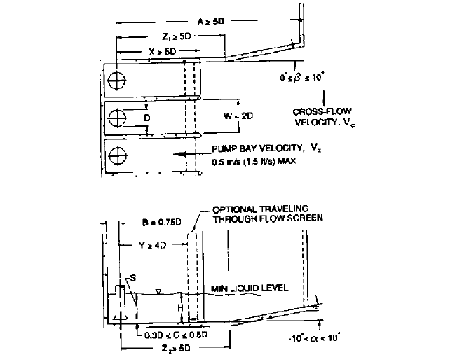
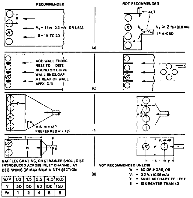
FIGURE 2 Recommended intake structure layout (American National Standard for Pump Intake Design,
ANSI/HI 9.8-1998, Reference 1)
fish away.The discharge into the forebay can be pipe velocity because the turbulence will be
dissipated by lower outlet velocities [2 ft/s (0.6 m/s)] through trash racks and traveling
screens. From this point on to the pump chamber, the velocity should be low and constant.
Any necessary change in inlet channel dimensions should be made gradually. Tapering
walls should not diverge at more than a 14 degree included angle. If it is necessary to slope
the floor, a maximum of 7 degrees is recommended and, if possible, the floor should level
off before reaching the pump area, as far back as possible. No sharp drops (waterfall effect)
should be permitted.
If the inlet channel is a closed pipe with full-wetted perimeter, pipe velocities can be
used up to a distance from the pump chamber where the tapered wall rule can be applied.
This means that the pipe size would be increased in accordance with the rules for maxi-
mum taper rate to ensure that the velocity as it discharges into the pump chamber is not
over 1.5 ft/s (0.46 m/s). Unless the inlet velocity into the pump chamber is kept below 1.5
ft/s (0.46 m/s), extensive baffling and additional space will be necessary, and this can only
be effectively determined by model testing of the pit.
RECIRCULATING SYSTEM
—
COOLING TOWER For cooling tower systems, the pump pit is nor-
mally adjacent to the tower basin. Cooling tower basins are shallow, usually not more than
6 ft (1.8 m) water depth. Because pumps will require more submergence than this, a slop-
ing ramp or sharp drop-off will be required if pumps are to be placed close to the basin.
This will save initial costs for excavation and concrete work, but the resulting poor flow
patterns conditions will cause endless pump problems.
Some successful small installations have been built with downslopes of 15 degrees or
more, but tower basin outlet velocity has been no more than 2 ft/s (0.6 m/s) and the downs-
lope widened as it approaches the pump pit. For low flows, low velocities, and fortunate
10.1 INTAKES, SUCTION PIPING, AND STRAINERS 10.7
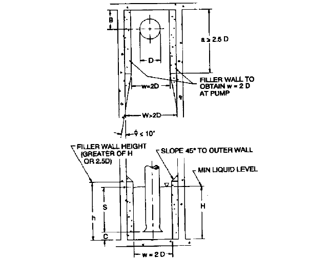
FIGURE 3 Filler wall details for proper bay width (American National Standard for Pump Intake Design,
ANSI/HI 9.8-1998, Reference 1)
arrangements of tower piers (lack of recirculation piping, and so on), such installations
may be operated with reasonable success. Others of similar design, however, have proven
to have disastrous effects on pump performance. Impellers and bearings may suffer rapid
deterioration under such conditions.
The best solution, but obviously the most expensive solution, is to build the pump pit
far enough from the tower basin to obtain a flat channel bottom. The channel should have
an average channel velocity of 1 ft/s (0.3 m/s) or less for a distance at least equal to A in
Figure 2, whether trash racks and screens are available. The slope from the basin floor to
the channel bottom should not be more than 10 degrees, preferably less than 7 degrees.
The basin exit width should be such as to make the exit velocity less than 2.5 ft/s
(0.75 m/s). If several tower piers are in the exit path, this velocity limit should be reduced
to 2 ft/s (0.6 m/s) or less. Upstream sides of the piers should be rounded off and the down-
stream sides should be tapered. Make the sidewalls of the downslope diverging so the
velocity at the bottom is no more than 1 ft/s (0.3 m/s).
Velocities should be based on the runout flow of one pump. All dimensions and veloci-
ties mentioned are limits. If they are used based on maximum required flow rate, and the
pump is selected for reasonable velocities, operation should be satisfactory. Obviously, if a
pump with high velocities (suction bell inlet, impeller eye, rotative speed) is selected, it will
require more submergence than a more conservatively designed machine. This will
increase the cost by requiring a deeper pump pit located further away from the tower
basin in order to perform satisfactorily.
A model test of the inlet structure is highly recommended if the best solution seems too
expensive, or if topography will not allow the ideal arrangement. A model with a variable
slope, variable sidewalls, and true representation of piers, pipes, and other obstructions
should enable a satisfactory design to be achieved with a possible net reduction in overall

10.8 CHAPTER TEN
TABLE 1 Recommended dimensions for Figures 2 and 3 (American National
Standard for Pump Intake Design, ANSI/HI 9.8-1998, Reference 1)
Dimension
Variable Description Recommended Value
A Distance from the pump inlet bell A = 5D minimum, assuming no
centerline to the intake structure significant cross-flow
a
at the
entrance entrance of the intake structure
a Length of constricted bay section near a = 2.5D minimum
the pump inlet
B Distance from the back wall to the pump B = 0.75D
inlet bell centerline
C Distance between the inlet bell and floor C = 0.3D to 0.5 D
D Inlet bell design outside diameter (see text)
H Minimum liquid depth H = S + C
h Minimum height of constricted bay h = (greater of H or 2.5D)
section near the pump inlet bell
S Minimum pump inlet bell submergence S = D (1.0 2.3 F
D
)
W Pump inlet bay entrance width W = 2D minimum
w Constricted bay width near the pump w = 2D
inlet bell
X Pump inlet bay length X = 5D minimum, assuming no
significant cross-flow at the
entrance to the intake structure
Y Distance from pump inlet bell centerline Y = 4D minimum. Dual-flow
to the through-flow traveling screen screens require a model study
Z
1
Distance from pump inlet bell centerline Z
1
= 6D minimum, assuming no
to diverging walls significant cross-flow
a
at the
entrance to the intake structure
Z
2
Distance from inlet bell centerline to Z
2
= 5D minimum
sloping floor
a Angle of floor scope a =10 to 10 degrees
b Angle of wall convergence b = 0 to 10 degrees (Negative
values of b, if used, require flow
distribution devices developed
through a physical model study)
f Angle of convergence from constricted f = 10 degree maximum
area to bay walls
a
Cross-flow is considered significant when V
C
0.5 V
X
average
cost. Actual pumps and valves should be used to create the flow in the pump pit, and
extremes of flow and submergence should be included in the test program.
Sometimes the cooling towers are on a hill, so a substantial drop in elevation provides
pressure available nearer the flow area. If dry-pit pumps are used, this pressure can be
utilized to reduce pump requirements. When this is done, the pump suction becomes a
pipe, and the latter part of this section should be consulted.
RECIRCULATING SYSTEM
—
POND WET PIT The intake structure in a cooling pond should be
located as far as possible from the inlet pipe to the pond to generate the maximum cool-
ing effect. If spray surface equipment is used, it should be so arranged in relation to the
intake building that a minimum surface disturbance is encountered. Prevailing winds
should be considered, and the building should be located on the lee (upwind) side of the
10.1 INTAKES, SUCTION PIPING, AND STRAINERS 10.9
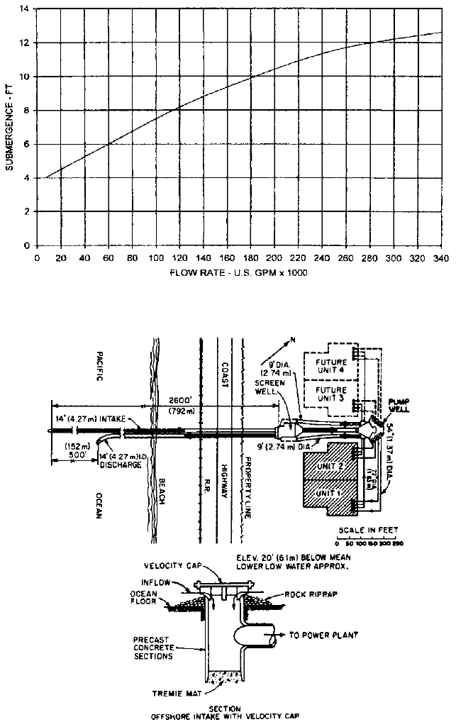
FIGURE 4 Flow rate vs. submergence over suction bell for vertical wet pit pumps. (U.S. gpm 0.227 = m
3
/h, ft
0.305 = m).
FIGURE 5 Ocean intake with velocity cap to minimize fish pickup
10.10 CHAPTER TEN
pond. If side and bottom areas might be easily disturbed to include silt in the flow, riprap—
a wall or covering of stones thrown together randomly—should be applied to approach
slopes as well as to bottom mats well beyond the inlet wing walls.
The handling of silt is usually not desirable in a pumping system. A high velocity
through the pump will accelerate wear. At low velocity points in the system, silt will set-
tle out and produce higher velocities, and more wear will occur as a result of the area
blockage. If space is available, a silt-settling basin can be constructed ahead of the inlet
basin. Cross baffles should be provided to slow the inlet flow to a velocity less than 1 ft/s
(0.3 m/s). Most stream debris will settle out at this velocity, and the flow into the pump
suction pit will be relatively clean, preventing the deposit of additional silt around the
pump suction bell. If space is not available for silt beds in large-capacity installations, the
main channel can be furnished with a weir across the flow path. The height of the weir
should be selected to give an overflow depth above the weir of not more than one-third to
one-fourth the water depth just preceding the weir. The velocity over the crest should not
exceed the intake channel velocity. Weirs of this type are particularly effective when the
intake channel is at right angles to the supply mainstream.
In areas where river levels vary considerably throughout the year, problems arise not
only from silt and debris accumulation, but from the structures required to prevent dam-
age to motors and electrical switch gear. If the required flow is moderate, a system known
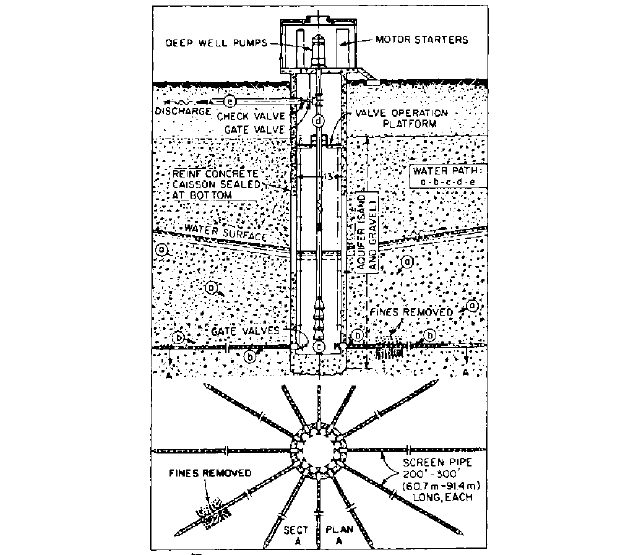
as the Ranney well (Figure 6) can be constructed. A Ranney well is a concrete silo 13 ft
(4 m) in diameter, which becomes the collecting basin and pump well. It may be situated
in or near a river and can be partly below and partly above water level with settings up to
100 ft (30 m). Small perforated pipes radiate horizontally from the base of the well and tap
FIGURE 6 Ranney well collects into a pool from underground strata (Ranney Method Division, Pentron
Industries)
10.1 INTAKES, SUCTION PIPING, AND STRAINERS 10.11
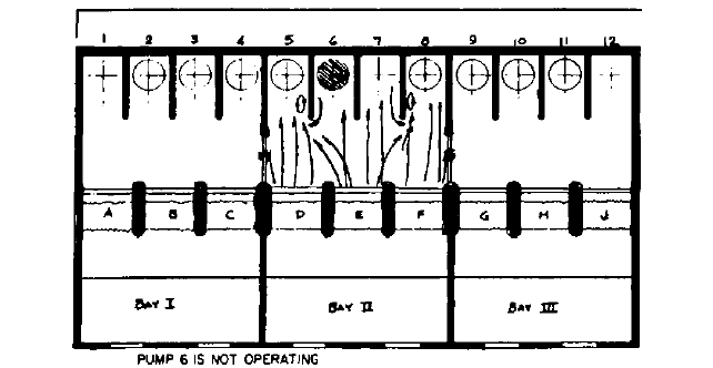
FIGURE 7 Empty spaces on nonoperating pumps cause vortexing at wall ends because of flow reversal.
into porous strata, bringing small flows of water into the main well. This water can then
be pumped from the well with a deep-well wet-pit vertical pump.
Multiple Pumps Some pump requirements are easily met with 100% capacity single
pumps, but more reliability usually requires two 50% or three 33% pumps, or, if the ser-
vice is sufficiently critical, three 50% or four 33% pumps, and so on. There are practical
limits of size for various pump types, so large flow demands will undoubtedly call for a
multiple pump arrangement.
The problem arising from multiple pumps arranged in a common pit is from the
probable nonuse of some of the pumps while others are operating. This can cause vari-
ables in flow patterns that may lead to eddying and vortexing (Figure 7). Installation of
separating walls in the common pit may introduce additional problems because the
ends of the separating walls can create eddy currents in the corners at the unused
pumps. A back vent in the dividing wall will relieve this situation, provided it vents at
the water surface (Figure 8b left). If walls are extended past the screens and trash racks
to a forebay, this problem will not occur, but the design has then become that of a single-
pump basin.
The same velocity rules apply to multiple arrangements as to single-pump basins. Odd
arrangements should be avoided even when they look invitingly symmetric
—
fan-shaped,
round, radial, peripheral
—
all have directional problems that are not easily overcome. A
basic pit design, consisting of a number of equally-sized pumps in a common pit basin with
flow entering parallel and straight in at 1 ft/s (0.3 m/s) or less, would not need to be model
tested to assure reliability (Figure 8a left). If separating walls are required for structural
support, and they are properly shaped and vented, no model test is recommended. The
pumps should be located at the extreme rear of the pit so the whole approach assumes the
characteristics of a suction pipe. Individual pump manufacturers may vary the location of
the pump relative to the pit bottom, velocity of inlet spacing, and so on. It has been found
that some of these variations require additional splitters or baffles below the pump, up the
back wall behind the pump, or centered in the flow ahead of the pump. If so, a model test
should be run and the additional pit cost weighed against other alternatives (changing the
pit shape, pump location, pump size, and pump speed).
A dry-pit pump installation will have the pumps located either in a dry well at or below
wet well water level (Figures 1e and 1f) or directly above the wet well and using a suction
lift (Figures 1g and 1h), which calls for priming equipment. The additional cost of priming
equipment (vacuum pumps, and so on) may be partially offset by the additional space and
valve requirement of the first option. In either case, the suction piping in the wet well
10.12 CHAPTER TEN
FIGURE 8 Using basics of good pit design precludes the need for model testing (Hydraulic Institute Standards,
13th Edition, 1975—out of print).
should be treated in the same fashion as the pump suction bells in wet-pit installations as
far as spacing, direction, and velocity of flow are concerned.
When the pump is installed at an elevation that may be below the water level in the
suction pit, a valve must be installed at the suction of the pump. The temptation to reduce
the inlet size to use a smaller valve should be avoided. Pipe size at a pump inlet may
decrease into the pump down to the pump suction size, but it would not be reduced below
that size and then have to increase again as it enters the pump. The pipe in the wet well
should preferably have a bell end and project downward.The minimum water level above
the top edge of the pipe or the lip of the bell should be at least 5 ft (1.5 m) for a recom-
mended entrance velocity of 5 ft/s (1.5 m/s). The bell mouth should protect downward to
assure uniform inlet flow and to attain maximum submergence.
A wet-pit intake style that closely approximates a suction pipe arrangement and
uses what is essentially a dry-pit pump has been expanded by the U.S. Department of
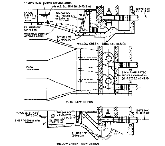
the Interior, Bureau of Reclamation to an elbow-type suction tube design. This incorpo-
rates a formed concrete suction inlet with a swing of 135 degrees in the vertical plane
and a gradual decrease in area to the suction eye of the pump (Figure 9). The resulting
design saves considerable excavation in the wet well area, reduces losses in the pump,
10.1 INTAKES, SUCTION PIPING, AND STRAINERS 10.13
FIGURE 9 Improved 135° design of Bureau of Reclamation elbow suction tube inlet (U.S. Department of the
Interior, Bureau of Reclamation)
and allows a smaller, higher-speed pump to be used. With higher velocities, debris
dropout is reduced so silt buildup does not occur as readily and a smaller trashrack area
remains effective longer. These inlets are independently self-sufficient and may be
grouped into multiples as long as the forebay is designed to adhere to the basic design
rules for wet-pit approach channels. Additional guidelines on the proportions of formed
suction intakes are included in the Hydraulic Institute Pump Intake Design Standard.
Considerations for either single- or multiple-pump pit design relate primarily to even
flow and low velocity into the pump. At the leading edge of the pump impeller (suction)
vanes, this velocity will be increased and the direction of flow violently changed. To make
the transition from pit flow to pump flow is the work of the pump designer. Some pump
designs include ribs in the suction bell; others do not. It is obvious that the transition from
parallel flow at 1 ft/s (0.3 m/s) to right-angle rotating flow at 15 to 20 ft/s (4.6 to 6.1 m/s)
requires a high degree of skill in matching the suction bell to the impeller. If the pump is
not designed to handle a wet-pit installation as described in previous paragraphs, a turn-
ing vane pit may be required.
Suction Pit Turning Vanes Figure 1c illustrates how turning vanes are used to guide
the flow of water into the inlet of a vertical volute dry-pit pump. Figure 1k shows the same
for the suction bell of a vertical diffuser wet-pit pump. If these pumps were connected to
an inlet sump without turning vanes, as illustrated in Figures 1a and 1j, a wider and
longer channel would be required to feed the suction bell from all directions. The pumps
10.14 CHAPTER TEN
with turning vanes an narrower inlet channels may be desirable as multiple pumps can
be spaced closer together providing screen width requirements do not dictate spacing.
Comparing depth of pit bottom below pumps with and without turning vanes, the fol-
lowing is to be noted. The excavation beneath a vertical volute dry-pit pump with turning
vanes can be slightly less than the excavation beneath the same pump with no vanes but
with a suction bell. The velocity approach into the closed portion of the channel beneath
the pump can be as high as 3 ft/s (0.9 m/s) if turning vanes are used at the design flow;
but it should be limited to 1.5 ft/s (0.46 m/s) with no turning vanes. Although the suction
bell design requires a wider channel than a vaned inlet (approximately two bell diame-
ters), this is not wide enough and the channel must be made deeper to meet the lower
velocity requirement for this type of inlet. When turning vanes are used with a vertical
diffuser wet-pit pump, the pit must be excavated deeper than would be required if no
vanes were used. This additional depth is required to form an elbow in the narrower chan-
nel and provide equal flow distribution to the impeller. Design velocity at the inlet vanes
is 3 ft/s (0.9 m/s).
The setting of the lip of the suction bell and the pump impeller below design low-water
level for volute dry-pit pumps must be the greater of the dimensions required to
• Prevent vortexing (ANSI/HI dimensions)
• Provide adequate NPSH at the centerline of the impeller
• Provide a level of water sufficient for the unit (impeller) to be self-priming
As an alternative to the use of turning vanes under a vertical volute dry-pit pump, the
long-radius suction elbow inlet illustrated in Figure 1b offers some advantage in reducing
the width and depth of excavation under the pump. The inlet velocity to the long-radius
elbow, which is usually formed in concrete, is preferably no greater than 3 ft/s (0.9 m/s) at
the design flow rate.
A decision to use turning vanes should not be based on a guarantee that there will be
an increase in pump efficiency. The design of the vanes
—
their number and spacing
—
is
still an art more than a science, and it is difficult to prove pump performance in the field.
Turning vanes can be effective in eliminating underwater vortices, a problem sometimes
associated with suction bells without turning vanes. It has been observed during model
testing that the suction bell, as illustrated in Figure 1a, must be placed closer to the back
wall than normally recommended for open channel inlets (similar to that in Figure 1j), to
prevent underwater vortexing. The flow of water into a closed channel from an open pit
containing water of considerably greater depth creates an unequal flow pattern in which
the maximum velocity is along the floor. Also, there is little, if any, flow to the back side of
the suction bell down from the top of the channel. Unless the bell lip is close to the back
wall, flow along the floor and from the front only will overshoot the inlet and roll over,
back, and up into the bell, forming an underwater vortex. Although turning vanes can pre-
vent this, they may not prevent uneven flow distribution up into the pump impeller unless
they are properly designed. They may even cause hydraulic and mechanical unbalance,
which could result in noise, vibration, and accelerated wear of the pump bearings. For this
reason, model testing of the turning vanes is recommended.
Screens and Trashracks Although it may not be feasible economically to eliminate all
refuse from a pumping system, it probably will be necessary to limit the size and amount
of debris or sediment carried into the system. Depending on the probable source of debris,
such as a river subject to flooding with considerable flotsam in the runoff and with a very
loose bottom, or a lake at constant level without disturbing inlet flows near the structure
and with a solid bottom, the protection needed may include only a bar trashrack plus
rotating, flushed, fine-mesh screens. If sediment deposit is likely, a settling basin may be
required.
The designer must note that, if this equipment is useful, it will pick up debris and grad-
ually increase the velocity through the openings as the net area decreases with blockage.
When this occurs at the trashrack, the water level differential will build up, causing a
waterfall with increased velocity and turbulence on the pump side of the rack. In addition,
10.1 INTAKES, SUCTION PIPING, AND STRAINERS 10.15
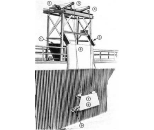
FIGURE 10 Trashrack with raking mechanism: (1) Large enclosed trash hopper contains debris discharged by
rake. Hinged door in end of hopper opens wide for debris removal. (2) Heavy-duty, single-drum hoist, push-button-
controlled with two separate cables
—
one for carriage, one for rake teeth. (3) Walking beam actuated by hydraulic
cylinder controls position of rake teeth. (4) Fixed sheave. Cable operating over stationary sheave raises and lowers
rake carriage. (5) Discharge guide flanges assure positive positioning of rake over trash chute prior to dumping.
(6) Dead plate, or apron, integral with superstructure guides rake to discharge point
—
prevents trash from falling
off rake prematurely. Design permits operation over 3.5-ft. (1.1 m) high hand rail. (7) Self-centering rack-guided
carriages allows rake to ride over obstructions in water during lowering cycle. Debris of all types picked up on
lifting cycle rather than forced to bottom of channel. (8) Rake mechanism assures positive removal of debris with
maximum carrying capacity. Hydraulic relief valve provides automatic overload relief. Teeth automatically open if
overload occurs, permitting load to drop off rake. No cable failures due to overload. (9) Wide, flanged rollers ride on
at least two rack bars (Envirex, Inc., a Rexnord Company)
the increase in velocity may pull more debris through the bars than can be tolerated. It is
best to rake these racks (Figure 10) frequently enough to keep the differential head across
the rack below 6 in (0.15 m). The spacing of the bars should be such that objects that
cannot be pumped would be excluded from passing through. This, in general, will call for
the bar spacing to be in proportion to the size of the pump. A pump manufacturer can
determine the maximum size sphere a pump will handle, and the bar spacing should be
limited to 50% of that value.The size of the bar, the lateral distance between supports, and
the pier spacing will influence the rate of debris accumulation and the allowable design
differential head.
Rotating screens (Figure 11) will remove trash of a much smaller size because the accu-
mulation is continuously removed and the open area is kept uniform. Finer screening than
that required by the pump may be necessary in installations where the liquid pumped
must pass through small openings in equipment serviced, such as condenser tubes or
spray nozzles (Figure 12). Screens are usually installed in conjunction with trashracks so
large, heavy pieces will not have to be handled by the screens. Because velocity through