Pump Handbook by Igor J. Karassik, Joseph P. Messina, Paul Cooper, Charles C. Heald - 3rd edition
Подождите немного. Документ загружается.

9.458 CHAPTER NINE
*Add loss through separate check valve if not integral with PRV.
should be scrutinized. Pertinent factors are the flow demand rate and hourly profile, pres-
sure conditions, and types of building occupancy.
FLOW DEMAND RATE AND HOURLY PROFILE Estimating water demand rate is one of the most
difficult and controversial subjects.To determine the water demand, many designers refer
to the classical Hunter curve (National Bureau of Standards, Report BMS79, by R. B.
Hunter) or a modified version of it for lack of a more accurate method. Numerous studies
have indicated that the Hunter method often results in very appreciable demand rate
overstatement. It should be noted that the Hunter curve was intended for determining
pipe sizes, not water demand.
The average hourly demand profile is helpful in proportioning the system demand rate
among the pumps in the system. Optimum selection results in the lowest total energy con-
sumption by the pumps while maintaining the demand requirements.
PRESSURE CONDITIONS Four accurate pressure values are required: design system pres-
sure, minimum suction pressure, maximum suction pressure, and minimum allowable
system pressure. The difference between design system pressure and minimum suction
pressure is used to determine the developed head of the pump at design flow. Inaccurate
values will result in incorrect impeller sizing and incorrect motor power selection.
The design system pressure can be calculated with reasonable accuracy. However,
when the water supply is from the municipal water main, obtaining accurate values of suc-
tion pressures for the proposed site of installation is very difficult because of the absence
of recent pressure data. Often the minimum and maximum pressures are haphazardly
estimated from average citywide values. A minimum suction pressure error as small as
5 lb/in
2
(35 kPa) could result in selection of the next larger motor.
The maximum suction pressure will determine the working pressures required of the
pumps and piping and whether there is sufficient pressure to justify a bypass connection
(Figure 3) paralleling the pumps.
Knowing the minimum allowable system pressure is helpful in setting controls associ-
ated with this pressure.
TYPE OF OCCUPANCY If the hourly demand profile is not available, the type of building occu-
pancy could be used to determine the standby capacity requirement, whether low-flow
shutdown is applicable, and the number of pumps for the system. Most pressure booster
manufacturers provide data for determining demand, capacity splits, and pump sizing.
Pump Sizing Procedures Information should be collected on system information and
component performance. The system information required is
Q
d
total design capacity, gpm (m
3
/h)
P
d
design pressure at system header outlet, lb/in
2
(kPa)
P
s
minimum available pressure at suction header inlet, lb/in
2
(kPa)
Q
1
, Q
2
, Q
3
design capacity of individual pumps, gpm (m
3
/h)
Components performance data required are
• Pump performance characteristic curve
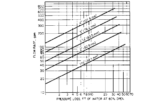
• Pressure-reducing valve (and check valve) flow chart* (Figure 6)
Next, the required pump total head at the maximum flow design condition should be
calculated:
(9)
where H required total head, ft (m)
H
d
design system pressure at PRCV outlet, ft (m)
H 1H
d
H
s
2 H
v
H
u
9.21 WATER PRESSURE BOOSTER SYSTEMS 9.459
FIGURE 6 Typical PRV or PRCV flow chart (ft 0.3048 = m; gpm 0.2271 = m
3
/h; in 25.4 = mm) (Cla-Val)
Add loss through separate check valve if not integral with PRV.
H
s
minimum design suction pressure, ft (m)
H
v
PRCV pressure loss, ft (m)*
H
u
sum of all unaccounted losses in the pressure booster package, ft (m)
For pressure booster applications, the PRCV is usually sized for a nominal pipe veloc-
ity between 8 and 18 ft/s (2.4 and 5.5 m/s). The pressure loss H
v
is based on the valve being
80% open (Figure 6). Operating the valve at less than full-open position is desirable for
good pressure regulation. The term H
u
represents the allowance for piping frictional losses
between the suction header inlet and the system header outlet at design capacity, exclu-
sive of the PRCV loss. Manufacturers of booster packages differ in determining this value.
Some ignore it completely to compensate for usual oversizing as the result of inaccuracies
in the design capacity and minimum suction pressure statements. Others assign a fixed
value, about 5 ft (1.5 m), or a percentage, about 3%, of the difference of system and suction
pressures (H
d
H
s
). It is recommended that some value be used.
Then determine the best combination of pump and PRCV sizes. The selection will
depend on whether the design criterion is least capital cost or lowest operating cost. Usu-
ally the smallest pump and PRCV combination will result in lowest first cost and the
pump equipped with the smallest motor will yield the lowest operating cost. Various
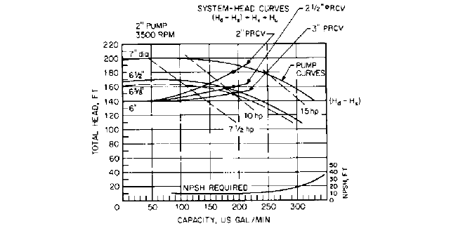
pump, PRCV, and motor combinations may be examined by plotting system curves (Figure
7) for two or three PRCV sizes on one or more pump performance curves.
The pumps tentatively selected should exhibit the highest efficiency at the most fre-
quent operating flow point on their head-capacity curves. When pumps are operated at
suction pressures higher than design minimum, the PRCVs will throttle the excess suction
head and maintain the same pump total head and constant design discharge pressure.
When the flow demand is less than the design maximum, characteristically, the head on
the centrifugal pumps will increase to some higher value on the pump head-capacity
curve. The PRCVs will reduce this excess head to maintain the constant design discharge
pressure. Therefore, each pump operates along its own head-capacity curve, which is also
the adjusted system-head curve.
9.460 CHAPTER NINE
FIGURE 7 System curves for PRCV sizing (ft 0.3048 = m; gpm 0.2271 = m
3
/h; hp 0.7457 = kW; in 25.4
= mm) (ITT Bell and Gossett)
*Due to the many approximations, decimal amounts are not used in the final results.
When several pumps are to be used, especially pumps of different sizes, their head-
capacity characteristics should be compatible. A pump having a shutoff total head less
than the system total head at any operating point (with or without other pumps operat-
ing) will not pump. Also, pumps should be so selected and controls should be such that no
one pump will operate at too low a flow; that is, at a flow less than the minimum recom-
mended for mechanical and hydraulic stability. If the minimum suction pressure is very
low, the net positive suction head required by the pumps throughout their operating flow
range must be checked (Subsection 2.3.1).
PUMP AND PRCV SELECTION EXAMPLE
Total system design capacity Q
d
380 gpm (86.3 m
3
/h)
Design capacity Q
1
, Q
2
190 gpm (43.1 m
3
/h)
Design pressure at system header outlet H
d
210 ft (64.0 m)
Minimum pressure at suction header H
s
70 ft at 100 ft NPSH
inlet (21.3 m at 30.5 m NPSH)
PRCV loss, Figure 6 H
v
36 ft (11 m) for trial 2-in (51-mm)
valve
Allowance for internal frictional losses H
u
5 ft (1.5m)
Calculate H:
In USCS units H (210 70) 36 5 181 ft* (Eq. 9)
In SI units H (64.0 21.3) 11 1.5 55.2 m
Table 2, calculate and tabulate H for all applicable PRCV sizes up to the design flow
rate of 190 gpm (43.1 m
3
/h). H
v
and H
u
terms vary as the square of the flow rate.
Now locate H at 190 gpm (43.1 m
3
/h) on the applicable pump curve. Select the pump
and PRCV combination that best satisfies the design criterion of least first cost or lowest
energy input.

9.21 WATER PRESSURE BOOSTER SYSTEMS 9.461
TABLE 2 Required head for pressure reducing valves
Flow, gpm (m
3
/h)
PRV size, in (mm) 0 (0) 50 (11) 100 (23) 150 (34) 190 (43)
2 (51) 140 (42.7) 143 (43.6) 151 (46.0) 166 (50.6) 181 (55.2)
2 (64) 140 (42.7) 141 (43.0) 146 (44.5) 153 (46.6) 160 (48.8)
3 (76) 140 (42.7) 141 (43.0) 143 (43.6) 147 (44.8) 151 (46.0)
Note: All values are head in ft (m).
1
2
Plot H values on the selected pump curve to obtain the system curves for the three
PRCV sizes (Figure 7). The plots reveal that the 3-in (76-mm) valve, a 10-hp (7.5-kW)
motor, and 6 -in diameter (162-mm) impeller are the proper selections.
Note that if the design capacity of the pump could be reduced to about 178 gpm
(40.4 m
3
/h, a 2 -in (64-mm) PRCV with the impeller sized for 6 -in (165-mm) diameter
may be used without additional power input. This choice reduces the cost and improves
the PRCV performance at low flow rates.
Using a 2-in (51-mm) PRCV would require a 15-hp (11-kW) motor operating at about
12.5 hp (9.3 kW) load. This choice is not energy effective.
The power required to drive the pump may be approximated by using the pump curve
and Eq. 7. The available NPSH is in excess of the required pump NPSH (Figure 7).
PUMP TYPES AND MATERIALS_________________________________________
Single-stage volute centrifugal pumps, followed by multistage vertical turbine diffuser
pumps in a suction tank, are most commonly used for domestic water pressure booster sys-
tems.The volute pumps can be end-suction with a vertically split case, double-suction with
an axially split case, or in-line. For high-pressure service, two-stage axially split case
pumps or multistage vertical turbine pumps may be selected.
In selecting the type of pump best suited for the application, such inherent character-
istics as low-flow recirculation, low-flow cavitation, high-flow cavitation, steepness of the
pump curve, noise, and operating efficiencies should be evaluated. These factors are dis-
cussed in Subsection 2.3.1.
The most often discussed factor in booster application is low-flow recirculation. Low
pump flow conditions do occur; they cannot be completely designed out of the system. Most
well-designed small pumps with positive (above atmospheric) suction pressure can oper-
ate safely in the low-flow region, with the only point of concern being water temperature
rise at or near shutoff flow. Should radial thrust be a major consideration, double-volute
pumps or diffuser (vertical turbine) pumps offer advantages.
Vertical pumps generally require less space. Pumps may be close-coupled to their dri-
vers, or, if not, a coupling requiring careful alignment is required. Close-coupled pumps
may require less maintenance, as there are no pump bearings. Shaft sealing may be either
packing or mechanical seal.
All pumps and drivers in packaged units are mounted on a common steel frame, but
individual bases for each pump and driver may be necessary for larger units.
The materials of construction for pumps, valves, and piping should be suitable for the
water quality and conditions furnished to the system. Because water impurities vary from
location to location, careful analysis is recommended. Federal and local agencies, such as
the Food and Drug Administration, may also prescribe allowable materials.
FURTHER READING __________________________________________________
American Society of Heating, Refrigerating, and Air-Conditioning Engineers. Equipment
Handbook, ASHRAE, Atlanta, GA, 1983.
1
2
1
2
3
8
9.462 CHAPTER NINE
ITT Bell and Gossett.“Domestic Water Service.” Bulletin TEH-1175, Morton Grove, IL, 1970.
ITT Fluid Handling Division. “Pressurized Expansion Tank Sizing/Installation.” Bulletin
TEH981, Morton Grove, IL, 1981.
Potter, P. J. Steam Power Plants, Ronald Press, New York, 1949.
Steel, A. High Rise Plumbing Design, Miramar, Los Angeles, 1975.

A. B. ZEITLIN
9.463
SECTION 9.22
HYDRAULIC PRESSES
TYPES OF PRESSES__________________________________________________
Hydraulic presses, both vertical and horizontal, are used in many industrial technologies.
Vertical press applications include forging presses with flat dies, used for hot work to
break down ingots and shape them into rolls, pressure vessels (mandrel forgings), forged
bars, rods, plates, and so on; forging presses with closed dies, used to process preheated bil-
lets into various shapes, such as aircraft bulkheads, engine supports, and main fuselage
and wing beams; and upsetting presses, used for the production of items with elongated
shafts
—
long hollow bushings, pipes, vessels, and so on. Horizontal presses are used pri-
marily for conventional hot extrusion. Cold hydrostatic extrusion is finding application in
the production of various end products and bulk items, such as very thin wire in long
strands.
ACCUMULATORS ____________________________________________________
Until about 1932, all power systems for hydraulic presses were operated with water. With
the advent of reliable, fast, high-pressure oil pumps, a trend of significantly less expensive
oil pumps developed.
Installations requiring a relatively uniform and constant supply of hydraulic power are
preferably designed with drives drawing the pressurized liquid directly from the pumps.
In installations with high power (and liquid) peak demands of short duration, it is in most
cases advantageous to arrange for a constant average flow of pressurized liquid from the
pumps while providing equipment in which pressurized liquid can be stored in times of
low demand and from which liquid can be drawn during demand peaks. These storage
9.464 CHAPTER NINE
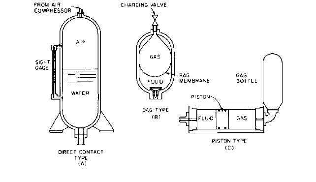
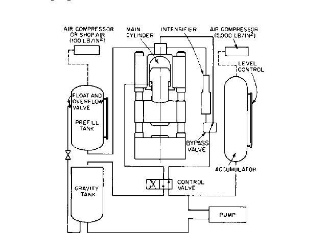
FIGURE 1A through C Accumulators
facilities are called accumulators and are illustrated in Figure 1. A modern accumulator
is buffered by a large pressurized gas (mostly air) cushion.
Until about 1960, the direct-contact surface between gas and liquid virtually precluded
the use of oil in accumulator installations for larger presses. Gas diffuses into oil under
pressure. When oil is discharged from the press at the end of the pressing cycle, the gas
begins to bubble out of the liquid; the liquid foams, and because of its large volume, this
foam is difficult to handle. This condition exists whether the pneumatic cushion is air or
nitrogen. In addition, if air is used as the pneumatic cushion, the oxygen diffused into the
oil oxidizes it, producing sludge and gum. (Spring- and weight-loaded accumulator instal-
lations have other serious drawbacks and have almost completely disappeared.)
A modification of the accumulator station uses a floating piston to separate oil from the
pneumatic cushion (Figure 1C).This design eliminates foaming and oxidizing, thus allow-
ing the inclusion of accumulators into oil systems.
Power plants operated with water are used exclusively in special cases (for instance,
where extreme precaution must be taken against fires caused by leaking oil). The increas-
ing viscosity of oil precludes the use of oil at very high pressures.
CENTRIFUGAL VERSUS RECIPROCATING PUMPS ________________________
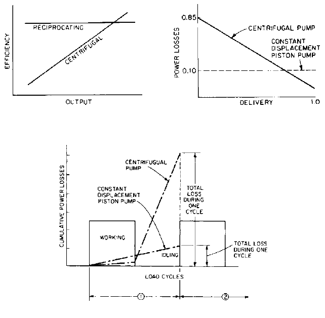
The competition between centrifugal and reciprocating pumps for hydraulic presses has
been decisively won by reciprocating pumps. Under full load, centrifugal pumps have
higher efficiency than reciprocating pumps (Figure 2). However, in press installations, the
power plants are idle a significant portion of the time. The losses during idling are only
about 10% of full load for reciprocating pumps and well over 60 to 70% for centrifugal
units. The total combined losses in installations with reciprocating pumps are less than
half the losses in centrifugal pump plants, as shown in Figures 3 and 4.
Reciprocating pumps for hydraulic presses that use water as the hydraulic medium are
generally of the single-acting multiplunger type. Although there are large installations in
operation using double-acting pumps, the faster vertical single-acting pump, which
requires less floor space, offers a considerable saving in capital expenditure and has
proved itself dependable in service. In most cases, this type of pump is used in conjunction
with an accumulator, which allows the averaging of demand and thus a reduction in
required pump capacity. There are, however, installations in which a vertical single-acting
pump drives hydraulic cylinders directly.
9.22 HYDRAULIC PRESSES 9.465
FIGURE 4 Comparison of load cycling losses
FIGURE 3 Comparison of pump power losses
FIGURE 2 Comparison of pump efficiency
Idling is controlled by remotely operated bypass valves or pump suction valve lifters
that take command from the operator, accumulator level control, or some other sensor-
monitoring press action.
Oil pumps most commonly used for the power strokes of presses are
1. Vane rotary constant-delivery pumps, generally for pressures not in excess of 2500
lb/in
2
(17,200 kPa)
2. Piston rotary constant-delivery pumps
3. Piston rotary variable-delivery pumps
The constant-delivery pumps require a bypass system for idling. This is generally
accomplished by an arrangement of directional control valves or by relief bypass valves.
The variable-delivery pump has the advantage of providing efficient press speed con-
trol and idling by an adjustment of piston stroke. In cases of multiple pump application,
constant- and variable-delivery pumps are often used jointly, their selection depending on
the speed ranges required. It is possible to obtain these pumps designed for use with non-
flammable liquid as a hydraulic medium.
Generally, both water and oil pumps in press applications are driven directly by elec-
tric motors, the motor speed matching the pump speed. Sometimes, on large water pumps,
a geared speed reducer is installed between motor and pump.
9.466 CHAPTER NINE
OPERATING PRESSURES _____________________________________________
Operating pressures in hydraulic presses have been slowly moving upward.The most pop-
ular level for water hydraulic installations is a rated pressure of 5000 lb/in
2
(34,500 kPa)
and an actual operating pressure of 4500 lb/in
2
(31,000 kPa). Intensifiers are used to raise
this pressure to between 6750 and 7500 lb/in
2
(46,500 and 51,700 kPa) in large presses,
which corresponds to a rated power of from 7000 tons (62,300 N) upward. When used, the
intensifiers are installed between the accumulators (and pump) on the low side and the
press on the high side.A bypass is always provided. For very large presses, pressures of up
to 15,000 lb/in
2
(10,300 kPa) have been suggested. In the former Soviet Union, designers
are using 15,000 lb/in
2
(10,300 kPa) regularly.
In oil hydraulic installations, 3000 lb/in
2
(20,700 kPa) is the most popular pressure
because of the availability of 3000-lb/in
2
(20,700-kPa) equipment from many reputable
firms (pumps, valves, fittings, and so on). However, there are now on the market excellent
units for pressures up to 6600 lb/ in
2
(45,500 kPa), and the tendency in new installations
is to provide 5000 lb/in
2
(34,500 kPa). Today, oil pumps for pressures as high as 9000 to
15,000 lb/in
2
(62,000 to 103,500 kPa) are being offered.
In the field of what is called ultrahigh-pressure equipment, pumps with direct action
up to 225,000 lb/in
2
(1.55 MPa) are available today.
DESIGN PROCEDURE_________________________________________________
Considerations and calculations required to dimension the hydraulic power plant for a
hydraulic press are given in Table 1. A standardized procedure for determining the basic
design features of the power plant for a hydraulic press is offered in the left column. The
right column gives an example of how the standard procedure should be used. The press
selected for the example is an open die press for forging ingots into billets or bars through
gradual reduction of cross section on narrow, flat dies that, at each stroke, penetrate sev-
eral inches into the hot metal (cogging). The ingot is advanced and rotated, and, when it
is close to the desired size, the surface is made smooth by the application of shallow-
penetration
—
- to -in (0.32- to 1.27-cm)
—
fast strokes (planishing) of the press (Figure 5).
1
2
1
8
FIGURE 5 Vertical forging press with double-acting cylinder

9.467
TABLE 1 Example of power plant design for a hydraulic press
Standard Procedure Example
Requirements:
Press rating T 6000 tons (53 MN)
Pull-back rating T
R
600 tons (5.3 MN)
Total stroke S
t
48 in (122 cm)
Maximum pressing stroke S
p
12 in (30 cm)
Fast advance speed v
a
360 in/min 6 in/s (5 cm/s) minimum
Fast return speed v
r
360 in/min 6 in/s (15 cm/s) minimum
Pressing speed V
p
required:
At full 6000-ton (53-MN) rating: 120 in/min 2 in/s (5 cm/s) maximum
At 4000-ton (36-MN) rating: 180 in/min 3 in/s (8 cm/s) maximum
At 2000-ton (18-MN) rating: 360 in/min 6 in/s (15 cm/s)
maximum
Rated operating cycles:
Cogging: 15 c/min, each cycle consisting of
Fast advance
—
4 in (10 cm)
Pressing
—
4 in (10 cm)
Return
—
8 in (20 cm)
Planishing: 80 c/min, each cycle consisting of
Advance
—
in (0.64 cm)
Pressing
—
in (0.64 cm)
Return
—
in (1.3 cm)
1. Selected: oil hydraulic system
2. Selected: p 5000 lb/in
2
(34 MPa)
3. in USCS units
in SI units
53
34
1.55 m
2
15,500 cm
2
A
6000 2000
5000
2400 in
2
1
2
1
4
1
4
1
3
2
3
1. Water or oil can be used as the liquid in a hydraulic system of a vertical or
horizontal press. The decision can be made in accordance with the general
discussion in this section. The generation of full pressure during planishing
is not required; because of rapid stroking, there would not be enough time
to pressurize the liquid fully and expand the cylinder fully. The pull-back
cylinders are kept continuously under pressure during planishing, thus
reducing the time required for valving. The generation of about 10% of
nominally rated pressure is considered sufficient for planishing.
2. Select operating pressure p in pounds per square inch (megapascals) of
the hydraulic system.
3. Determine the required effective pressing area A in square inches
(square centimeters) of the main plunger of the press:
where T is the rated power in tons (newtons).
A
T 2000
p