Pump Handbook by Igor J. Karassik, Joseph P. Messina, Paul Cooper, Charles C. Heald - 3rd edition
Подождите немного. Документ загружается.


9.448 CHAPTER NINE
TABLE 1 Comparison of significant factors for pressure booster systems
System type Advantages Disadvantages
Elevated gravity Simplicity, large storage Size and weight, water damage
tank capacity, low energy usage, potential, freeze potential if
reserve storage capacity for roof-mounted, corrosion and
fire protection contamination potential,
limited pressure for floor
immediately below tank,
possible unsightly
appearance, periodic
cleaning and painting
Hydropneumatic Location not critical, low energy Requires compressed air
tank usage, limited storage source, corrosion and
capacity, pump does not run contamination potential,
when there is no demand, large pressure variation,
operation in optimum pump relatively large, standby
flow range provision costly
Variable-speed Simple controls, off-the-shelf Slow response to sudden
drive: Fluid motor, standby provision demand change, may require
couplings less costly than for above heat exchanger to cool drive,
units slip losses result in lower
maximum speed and higher
motor power, requires
selective application, no
water storage
Variable-speed Low motor current inrush, Complex electric circuitry, high
drive: ac type precise pressure control, initial cost for low-power
higher than 3600 rpm units, may require special
possible, few mechanical motors, motor low-speed
devices, large power limitation, rapidly changing
capability at lower first cost technology, requires selective
application
Tankless Relatively low first cost, uses Continuously running lead
constant-speed time-proven components, pump, difficult to accurately
multiple pump compact size, inherent partial determine capacity split
standby capacity, extra among pumps, no water
standby capacity inexpensive, storage, problems associated
location not critical, good with low flow rates
pressure regulation
Limited-storage Shuts down during very low No significant disadvantages,
constant-speed water demand, uses time- tanks with high maximum
multiple pump proven components, standby working pressure may be
capacity inexpensive, location difficult to obtain
not critical, limited water
storage, no air-to-water
contamination with
diaphragm tank
heating and cooling systems.With an open-loop system, the static head above the pump is
not canceled by the down leg of the piping, and therefore the pump must develop a head
equal to or greater than the static head, even at zero flow (with suction pressure at
design). Review Sections 8.1 and 8.2 for further discussions on closed-loop systems.

9.21 WATER PRESSURE BOOSTER SYSTEMS 9.449
Variable-Speed-Drive Pressure Booster Systems Initial variable-speed drives were
fluid couplings, magnetic couplings, and liquid rheostat (wound rotor motor) drives. The
coupling-type drives were driven by a constant-speed motor, with the coupling output shaft
varying in speed. With the advent of solid-state electronics technology and circuit minia-
turization, most variable-speed drives currently used for pressure booster applications are
of the solid-state, ac, adjustable-speed type.These drives are discussed in Subsection 6.2.2.
Variable-speed drives are usually specified for their low operating cost potential. To
achieve the energy-savings goal, the system conditions should cause the drive speed to
vary between 50 and 75% of full speed during most of the operating period.
The pump speed, head, and flow relationships are expressed by the affinity laws:
• Flow varies directly as speed:
(1)
• Head varies directly as the square of the speed:
(2)
where Q flow rate, gpm (m
3
/h)
N pump speed, rpm
H pump total head, ft (m)
The required pump total head at design conditions is
(3)
where H required pump total head at design conditions, ft (m)
H
d
design system pressure at point of control, ft (m)
H
s
minimum design suction pressure, ft (m)
H
f
sum of all losses between H
d
and H
s
at design flow, ft (m)
At flow rates less than design conditions and suction pressures higher than the mini-
mum design pressure, the pump head requirement is reduced by the change in pipe fric-
tional losses H
f
and the additional suction pressure H
s
available.Also, because of the rising
characteristic of the centrifugal pump performance curve as the flow decreases, an excess
head is developed by the pump. All of these changes will alter the required pump total
head and the pump speed from the design (maximum) values.
For a single operating pump unit, design maximum speed will be required at design
minimum suction head and design maximum flow. Minimum speed will be required at
maximum suction head and minimum flow. The procedure required to determine the
speed range of the pump driver requires construction of the system-head curve, the pump
head-capacity curve (see Section 8.1), and the affinity curve. Rearranging the affinity
equations (Eqs. 1 and 2), the speed changes are calculated:
(4)
(5)
where the subscripts 1 and 2 represent the higher and lower speed values, respectively, for
pump conditions at the same specific speed (see Subsection 2.3.1) or along the same affin-
ity line.
N
2
N
1
a
H
2
H
1
b
1>2
N
2
N
1
a
Q
2
Q
1
b
H 1H
d
H
s
2 H
f
H
2
H
1
a
N
2
N
1
b
2
Q
2
Q
1
N
2
N
1

9.450 CHAPTER NINE
FIGURE 1 System and pump curves to determine speed reduction for the 2-in (51-mm) pump in Examples 1 and 2.
(ft 0.3048 m; gpm 0.2271 = m
3
/h)
The following examples illustrate how changes in flow rate, pipe frictional losses, and
suction head affect pump speed.
EXAMPLE 1 With no change in suction pressure
—
first (design) conditions:
H
d
193 ft (58.8 m)
H
s
50 ft (15.2 m)
H
f
7 ft (2.1 m)
Q 190 gpm (43.1 m
3
/h)
N 3500 rpm
H (193 50) 7 150 ft (45.7 m) (Eq. 3)
Second conditions:
H
d
193 ft (58.8 m)
H
s
50 ft (15.2 m)
H
f
1.9 ft (0.58 m)
Q 100 gpm (22.7 m
3
/h)
N to be calculated
H (193 50) 1.9 144.9 ft (44.18 m) (Eq. 3)
The 3500-rpm pump head-capacity curve, the system-head curves, and the affinity
(square) curves are shown in Figure 1. The operating points are lettered. Point A is for
maximum flow at minimum suction head (design conditions). Point B is for lower flow
at minimum suction head at a speed to be determined. The reduced piping losses
between head points H
d
and H
s
are represented by the system-head curves.
To determine the approximate speed at point B, it is necessary to use trial and error
because the flow and head ratios in Eqs. 4 and 5 are not known. The following proce-
dure may be used to estimate the speed (Figure 1):
1. Draw an affinity (square) curve passing through the zero-flow/zero-head point and the
lower operating point (point B) and intersecting at head-capacity curve of known
speed (point C).

9.21 WATER PRESSURE BOOSTER SYSTEMS 9.451
2. Read the probable flow rate at point C, the point of intersection between the affinity
curve and the pump curve of known speed.
3. Calculate the head relative to the flow rate read at point C, based on the square curve
relationship:
(6)
where subscripts 1 and 2 represent the values at the 3500-rpm and lower speeds
(points C & B), respectively.
4. Compare the head calculated in step 3 with the head of the pump curve (point C) of
known speed at the probable flow rate of step 2. If the values differ significantly, try
another flow rate and repeat steps 3 and 4.
5. Using the accepted head from step 4, calculate the speed at the operating point (point
B) using Eq. 4 or 5. The equation not used may then be used for verification.
For this example, the estimated flow rate at point A (step 2) is 104 gpm (23.6 m
3
/h) and
the calculated head at the same point (steps 3 and 4) is
The speed at the operating point (point B) is
(Eq. 4)
Check:
(Eq. 5)
The speed change is
EXAMPLE
2 With change in suction pressure
—
first conditions: same as Example 1.
Second conditions: same as Example 1, except
Operating point B¿ and other curves related to this example are shown in Figure 1.
Again by trial and error, the flow rate and pump head at the intersection of the affin-
ity curve and the 3500-rpm pump curve (point A¿) are 134 gpm (30.4 m
3
/h) and 152.4 ft
(46.45 m). The speed at the operating point is
(Eq. 4) N
2
3500 a
100
134
bor3500 a
22.7
30.4
b 2612 rpm
H 1193 1102 1.9 84.9 ft 125.88 m2 1Eq. 32
H
s
110 ft 133.5 m2
3500 3365
3500
100 3.9%
N
2
3500 a
144.9
156.7
b
1>2
or3500a
44.17
47.76
b
1>2
3366 rpm
N
2
3500 a
100
104
bor3500 a
22.7
23.6
b 3365 rpm
H
1
144.9
a
100
104
b
2
156.7 ftor
44.18
a
22.7
23.6
b
2
47.76 m
H
1
H
2
a
N
2
N
1
b
2

9.452 CHAPTER NINE
Check:
(Eq. 5)
The speed change is
These examples indicate that the speed of the pump is not significantly affected unless
there is an appreciable change in suction pressure.
For optimum performance, it should be confirmed, after the speed has been deter-
mined, that the most often occurring flow demand range is ideally near the pump’s maxi-
mum efficiency.
Generally, the design point at maximum speed should be selected to the right of the
pump’s best efficiency point. The operating flow range at different speeds should be within
the hydraulically and mechanically stable ranges of the pump.
The pump shaft power at any specified speed is
in USCS units
in SI units (7)
where H pump total head, ft (m)
Q flow rate, gpm (m
3
/h)
sp. gr. specific gravity of fluid
E pump efficiency, % (expressed in decimal equivalent)
H, Q, and E are values from the pump performance curve for the specified speed and
impeller size.
The motor power is the same as the shaft power for pumps driven directly by the motor.
For pumps driven through intermediate variable-speed couplings, the motor power must
also include the drive slip and fixed loses.
When the required design flow exceeds the capacity of a single pump, several pumps,
including possibly one constant-speed unit, can be arranged to operate in parallel. Two
methods of staging the pumps are usually used:
1. The first pump is operated in the variable-speed mode until its maximum speed is
reached; the second pump, also a variable-speed unit, is energized. Now both pumps
are operating in parallel at the same reduced speed. This sequence is repeated for the
other pumps.
2. The first pump is operated in the variable-speed mode until its maximum speed is
reached and is then locked in at this speed to operate as a constant-speed pump. The
second pump is energized and operates in the variable-speed mode. The sequence is
repeated for the other pumps.The speed variation of the second pump is relatively small
because it must develop the same head as the first pump operating at maximum speed.
Because the flow rate through the second pump is less, its speed is affected by the
increase in total head available from the rise in the pump performance curve.
Which method of sequencing is selected depends on economics, equipment redundancy,
and other considerations. For example, with the first method, both pumps must be fur-
nished with variable-speed drive units. With the second method, only one variable-speed
drive unit is required if it is an electronic type because the first pump is locked in by sep-
arate electric means.
kW
QH1sp. gr.2
367E
hp
QH1sp. gr.2
3960E
3500 2612
3500
100 25.4%
N
2
3500 a
84.9
152.4
b
1>2
or3500a
25.88
46.45
b
1>2
2612 rpm
9.21 WATER PRESSURE BOOSTER SYSTEMS 9.453
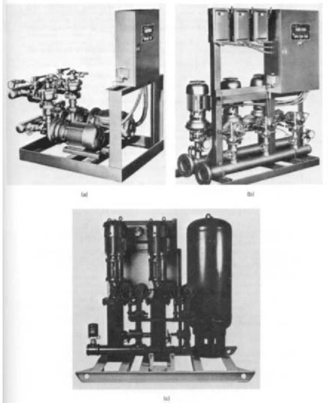
FIGURE 2 Constant-speed multiple-pump pressure booster systems: (a) horizontal end-suction volute pumps
(ITT Bell and Gossett), (b) vertical end-suction volute pumps (ITT Bell and Gossett), (c) vertical turbine pumps with
limited storage (SynchroFlo)
The sole function of the pumps is to maintain constant pressure at the control point;
therefore, the controller selected must be pressure-actuated. The type (follower signal) of
controller chosen depends on the type of speed change signal acceptable by the variable-
speed control unit. For electronic motor speed controls, such as variable-voltage and
variable-frequency units, typical follower signals are low-voltage dc, milliamp dc, 135-ohm
potentiometer, and pneumatic.
Tankless Constant-Speed Multiple-Pump System The major components of this sys-
tem (Figure 2) are
9.454 CHAPTER NINE
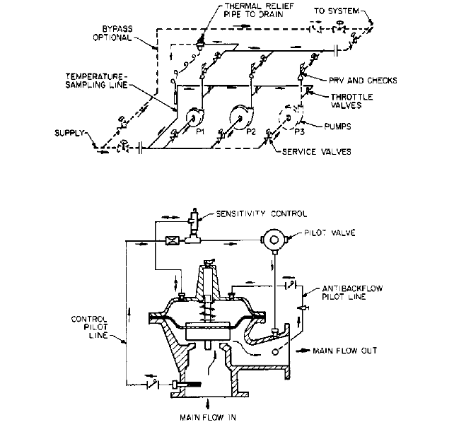
FIGURE 4 Typical pressure-reducing and check valve to maintain constant system pressure and prevent
backflow (Cla-Val)
FIGURE 3 Constant-speed multiple-pump pressure booster schematic (ITT Bell and Gossett)
1. One or more pumps, with two or three most common
2. A combination pressure-reducing and check valve (PRCV) for each pump (parallel-
piped PRCVs are used with larger sizes; separate pressure-reducing valves and check
valves may be used)
3. An automatic sequencing control panel
4. When factory assembled, a steel frame for the entire unit
PIPING ARRANGEMENT AND FLOW PATH A schematic of the piping arrangement and flow path
in a constant-speed multiple-pump system is shown in Figure 3. Supply water under fluc-
tuating pressure enters the suction header and flows into the pump, where it is boosted to
a higher pressure. This varying high-pressure water enters the PRCV (Figure 4), and the
pressure is reduced to the constant pressure desired over the design flow range. Flow rever-
sals through the idle and parallel pump circuits are prevented by the checking feature of
the PRCV, which also dampens the pressure fluctuations caused by sudden flow changes.
When only minor changes in supply water pressure are anticipated, such as from a
nonpressurized tank, and the pump head-capacity curve is relatively flat, silent check
valves without pressure-reducing feature may be used.This will result in a slight increase
in discharge pressure above the desired design constant pressure. When pumps of differ-
ent sizes are used, care should be exercised to avoid having the higher-head pump force
9.21 WATER PRESSURE BOOSTER SYSTEMS 9.455
the lower-head pump to shut off or to operate at less than minimum design pump flow. A
decrease in flow from a centrifugal pump must be accompanied by an increase in pump
total head as required by the pump head-capacity curve. If check valves only are used, it
is preferable to have all pumps and valves identical to avoid unbalanced flows.
Operating the pumps at shutoff (no flow) will cause the water temperature in the pump
castings to rise (Subsection 2.3.1). To keep the temperature in the pumps within a safe limit,
the heated water is relieved through the thermal relief valve. This valve may be either a self-
actuated (thermostatic) type or a solenoid valve actuated by a temperature controller.
PUMP CONTROL PANEL One of the advantages of a factory-assembled pressure booster
package is the prewired, pretested, pretubed, mounted control panel that requires a min-
imum of field connections. In addition to providing for the proper sequencing of the pumps,
the control panel should contain electrical interlocks for the operating and safety controls
and circuit connections for remote control units.
Standard items and optional equipment vary considerably from one manufacturer to
another. The components usually included with a standard panel are listed:
Steel enclosure Starters
Control transformer Sequencing controllers
Control circuit protector Pump failure interlocks
Selector switches Minimum-run timers
Low-suction pressure control Time delays
Pilot lights
Optional features that may be available:
Power supply fused disconnects or circuit breakers Low system pressure control
Enclosure door interlock Low water level control
High water temperature control Emergency power switchover
High system pressure control Unit failure alarm
Pump alternation Low-flow shutdown
Program time switch Miscellaneous enclosure types
Elapsed time meters Power economizer circuit
Additional pilot lights
Most factory-wired panels conform to one or more of the consumer safety agencies,
such as Underwriters’ Laboratories (UL), National Electrical Code (NFPA/NEC), and
Canadian Standards Association (CSA) and are furnished with a label so indicating.
PUMP CONTROL SEQUENCE A typical elementary wiring diagram provides the following
sequences of events. With both pump selector switches in the auto mode and all safety
and operating controls in run status, the lead pump starter is energized, starting pump
1. As the system water demand increases, a staging control switch, which senses motor
current, flow, or system pressure, starts pump 2. Pump 2 continues to operate until the
decreasing water demand causes the staging control switch to open, stopping pump 2. If
the circuit is provided with a minimum-run timer, pump 2 will continue to run for the set
time period regardless of the staging switch status. This timer prevents pump 2 from
short-cycling during rapidly fluctuating demand periods.
For test purposes and emergency operation, both pumps may be operated by placing
the selector switches in the hand mode. In this position, most of the safety and operating
controls are bypassed.
Should pump starter 1 fail to operate because of an overload heater relay trip or starter
malfunction, a failure interlock switch automatically starts pump 2.
Pump 1 will run continuously unless the circuit is provided with shutdown features,
such as high-suction pressure control and/or low-flow shutdown control.

9.456 CHAPTER NINE
Many units are specified for manual or automatic alternation of the equally sized
pumps. This feature is intended to equalize the wear among the pumps and associated
components. Alternation of any pump designated for standby duty (emergency use) may
not be prudent. The standby pump should be preserved until needed, similar to an emer-
gency power generator.
Limited-Storage Constant-Speed Multiple-Pump System The most notable short-
coming of the tankless multiple-pump system is the need for a continuously running
pump, even at zero water usage. This drawback is remedied by the addition of a pressur-
ized storage tank connected to the high-pressure side of the piping system with low-flow
shutdown controls to stop the pumps.
The limited-storage system is not a scaled-down version of the hydropneumatic sys-
tem. It differs in three important aspects:
1. The primary function of the tank is water storage.
2. Tank pressure is developed by the booster pump.
3. Air and water in the tank are separated by a flexible barrier (diaphragm, bladder) to
eliminate direct interaction between the gas and water in the tank. The barrier also
prevents the gas from escaping when the tank is emptied of water.
SEQUENCE OF OPERATION CONTROL CIRCUITRY During periods of normal water usage, the
operating sequence is that of the tankless unit. As the water flow approaches zero, a low-
flow sensing device stops the pumps.The tank provides the water needs during the shut-
down period until the water pressure diminishes to the minimum allowable value. At this
time, a pressure switch starts the lead pump to restore the pressure and recharge the
tank with water.
The low-flow device may be a flow switch, a pressure switch, or a temperature-actuated
switch and must be capable of switching at flows below 5 gpm (1.14 m
3
/h).
The tank should be sized for sufficient drawdown volume (water available from tank
during shutdown) to avoid excessive pump cycling.
RELATIONSHIPS BETWEEN TANK SIZE, DRAWDOWN VOLUME,AND PRESSURE
The approximate for-
mula for sizing prepressurized diaphragm tanks at constant temperature is
(8)
where V
t
tank volume, ft
3
(m
3
)
V
e
change of gas volume in tank, ft
3
(m
3
)
P
f
final gas pressure lb/in
2
(kPa) abs
P
0
initial gas pressure, lb/in
2
(kPa) abs
The corresponding relationships of water volume and pressures in the tank are
• V
e
is equal to the drawdown volume.
• P
f
is the water pressure at the end of the drawdown cycle, the minimum allowable sys-
tem pressure.
• P
0
is the water pressure at the beginning of the drawdown cycle or at the termination
of the charging cycle.
TANK LOCATION Because both P
f
and P
0
are influenced by the static head above the tank
and the available charging pressure, the location of the tank and point of connection to
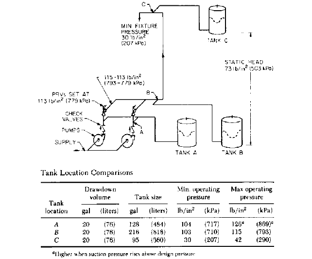
the system should be carefully selected. Connecting the tank at A in Figure 5 provides
the highest available tank charging pressure because this pressure is not affected by the
reduction through the PRVs. However, there are several disadvantages to this point of
connection:
V
t
V
e
1
P
f
P
0
9.21 WATER PRESSURE BOOSTER SYSTEMS 9.457
FIGURE 5 Relative effect of tank location on tank size and pressure for equal draw-down volumes (ITT Bell and
Gossett)
1. The highest static pressure is applied to the tank because the pumps are usually
located on the lowest floor of the building.
2. The tank may be subjected to high working pressure because any increase in suction
pressure above the minimum design pressure is additive to the pump head.
3. The tank and all alternated lead pumps must be interconnected.
4. A silent check valve must be placed between the tank connection point and the pump
discharge nozzle.
Connecting the tank in B in Figure 5, downstream of the PRVs, will eliminate disad-
vantages 2, 3, and 4. The available charging pressure is less, and therefore a larger tank
is required. However, tank location is not critical.
Locating the tank on the upper elevation of the building, such as at C, reduces the sta-
tic head pressure on it; consequently, a smaller tank will suffice. The maximum design
working pressure is also lower, and therefore it may be possible to use a tank with a lower
pressure rating at less cost.
PRESSURE BOOSTER SYSTEM SIZING__________________________________
Design Data
The proper sizing of a pressure booster system is subject to the accuracy of
the design data available. Experience has indicated that the greatest single cause for unsat-
isfactory pressure booster performance is oversizing. Submitted data may be rough esti-
mates or historical data not relevant to the location; therefore, their source and accuracy