Pump Handbook by Igor J. Karassik, Joseph P. Messina, Paul Cooper, Charles C. Heald - 3rd edition
Подождите немного. Документ загружается.

9.468
4. Select three cylinders.
Center cylinder T
2
4000 tons (36 MN)
Two side cylinders T
1
T
3
1000 tons (8.9 MN)
Operating all three cylinders: T 6000 tons (53 MN)
Operating center cylinder alone: 4000 tons (36 MN)
Operating side cylinders alone: 2000 tons (18 MN)
5. A
1
A
3
2400 400 in
2
( 15,500 2580 cm
2
)
A
2
2400 1600 in
2
( 15,500 10,300 cm
2
)
Adjusted area A¿
1
A¿
3
415 in
2
(2680 cm)
Adjusted area A
2
¿ 1590 in
2
(10,200 cm
2
)
Total adjusted area A¿ (2 415) 1590 2420 in
2
[(2 2680)
10,200 15,600 cm
2
]
6. V
t
S
t
A¿ 48 2420 116,160 in
3
(122 15,600 1,903,000 cm
3
)
For cogging V
pc
4 2420 9680 in
3
per cogging stroke (10 15,600
156,000 cm
3
)
For planishing V
pp
2420 605 in
3
per planishing stroke (0.635
15,600 9900 cm
3
)
7. For 5000 lb/in
2
(34 MPa), the oil compressibility may be assumed at c
0
1.5%.
1
4
D
2
A
1600
0.785
45 in
a
1114 cm2
D
1
D
3
A
400
0.785
23 in
a
158.4 cm2
4
6
4
6
1
6
1
6
TABLE 1 Continued.
Standard Procedure Example
4. Select the number of cylinders N
c
comprising the main system of the
press and their individual ratings T
1
,T
2
,T
3
....
5. Subdivide A in accordance with selected ratings and determine the indi-
vidual diameters:
If any piston rods detract from the effective plunger area, their area
should be added to A before determining D.
6. Using the total stroke S
t
and the rated pressing stroke S
p
, determine the
geometric volumes V
t
and V
p
corresponding to these strokes.
7. Using a general compressibility curve, determine the compressibility c of
the liquid between atmospheric pressure and rated operating pressure.
D
A
A
0.785
a
It is customary to select diameters of large plungers in full-inch or -inch sizes; this requires adjustment of the area.
1
2
9.469
TABLE 1 Continued.
Standard Procedure Example
8. Assume s
h
30,000 b/in
2
(207 MPa)
where dem is the main cylinder diameter expansion and des is the side
cylinder expansion.
9. Compression of the liquid takes place along the entire length of the cylin-
der barrel. Assuming the length of the barrel to be approximately S S,
or 48 25 72 in (122 61 183 cm):
V
c1
72 2420 0.015 2614 in
3
V
c1
(183 15,600 0.015 42,800 cm
3
)
Omitting quantities small in the second order,
72 1.57 0.001 D
2
0113 D
2
(183 1.57 0001 D
2
0.287 D
2
)
For the center cylinder:
V
ec2
0.113 45
2
229 in
3
(0.287 114
2
3730 cm
3
)
For the side cylinders:
V
ec1
V
ec3
0.113 23
2
60 in
3
(0.287 58.4
2
980 cm
3
)
V
ec
229 (2 60) 349 in
3
[3730 (2 980) 5700 cm
3
]
Total additional volume of liquid required.
2614 349 2963 in
3
per stroke (42,800 5700 48,500 cm
3
)
V
ec
72
p
4
a2D
30,000
30 10
6
Db
1
2
a
207
207 1000
58.4 0.058 cmb
Side cylinders des
30,000
30 10
6
23 0.023 in
a
207
207 1000
114 0.114 cmb
Main cylinder dem
30,000
30 10
6
45 0.045 in
8. Assume a reasonable approximate level of hoop stresses s
h
along the
inner surface of the cylinder barrel. The cylinder diameter expansion will
be
where E modulus of elasticity, assumed to be 30 10
6
lb/in
2
(207 GPa)
9. On the basis of c
0
and s
h
, determine the volume of liquid required to com-
pensate for compression of liquid V
c1
as well as for expansion of cylinder
V
ec
. During planishing, the pressures rise to only about 10% of rated;
therefore, the compressibility of the liquid and expansion of the cylinder
may be neglected.
d
e
s
h
E
D

9.470
TABLE 1 Continued.
Standard Procedure Example
10. V 9680 2963 12,643 in
3
(156,000 48,500 204,500 cm
3
)
This value shows what additional burden can be imposed on the power
plant by unnecessarily generous dimensioning of the total stroke.
11. Fast advance time: 0.67 s
Pressing time: 2 s
Fast return time: 1.33 s
Valving time (3 switches) 0.45 s
Total cycle time 4.45 s
This time is too long to allow 15 cogging strokes per minute. Increase
fast advance and fast return to 480 in/min 8 in/s (20 cm/s) and press-
ing to 180 in/min 3 in/s (8 cm/s). Then
Fast advance time: 0.5 s
Pressing time: 1.33 s
Fast return time: 1 s
Valving time 0.45 s
12. 12,643 0.2 2528 in
3
(204,500 0.2 40,900 cm
3
)
8
8
4
3
4
8
8
6
4
2
4
6
10. Determine the total amount of liquid V required per cogging stroke.
11. Check whether specified speeds are compatible with the required number
of cogging strokes. If not, increase the specified speeds (or reduce the
number of strokes).
12. Determine the liquid requirements for the pull-back stroke (Figures 6
and 7). In general, the pull-back cylinders have an area equal to 10% of
the area of the main cylinders and twice as long a stroke as the pressing
stroke; in general, the required volume is therefore, with sufficient
accuracy:
V 0.1 2 0.2 V
9.471
TABLE 1 Continued.
Standard Procedure Example
13. Without an accumulator:
With an accumulator:
It is evident that the use of an accumulator will result in significant sav-
ings and in a substantial reduction of the peak load.
14.
11.5 0.125 1.63 m
3
2
53 4.4 57.4 ft
3
11.25 0.125 1.38 m
3
2
Total accumulator volume 44 4.4 48.4 ft
3
112 0.125 1.5 m
3
2
V
air
1polytropic2 12 32.9 395 gal
395
7.48
53 ft
3
110 0.125 1.5 m
3
2
V
air
1isometric2 1 32.9 329 gal 10 4.4 44 ft
3
a224
4 1.33
3600
40,900
10
6
0.125 m
3
b
V
s
985
4 1.33
60
2528
231
32.9 gal
32.9
7.48
4.4 ft
3
a
1204,500 40,9002 3600
10
6
4
221 m
3
>h 1acc2b
112.643 2,5282 60
231 4
985 gpm 1acc2
12,643 60
231 1.33
2469 gpm a
204,500
10
6
1.33
553 m
3
>hb
13. Determine the pumping requirements for the pump station with or with-
out an accumulator. Without an accumulator:
where V is the volume in gallons (cubic meters) required for one pressing
stroke and t
p
is the pressing time in seconds.
With an accumulator:
where V
tc
is the total volume in gallons (cubic meters) of pressurized liq-
uid required during one cycle and t
c
is the cycle time in seconds.
14. Determine size of the accumulator required to store the accumulated vol-
ume V
s
of liquid:
where V
R
is the volume required for the return stroke in gallons (cubic
meters).
Air volume required, based on 10% pressure fluctuation for isothermic
condition, is 10V
s
. For adiabatic or, more often, polytropic conditions and
10% pressure fluctuation, the air volume is
Although n 1.4 is the exponent for adiabatic compression, n 1.3 is
considered satisfactory, even for severe and demanding conditions, which
require full utilization of press stroke and a fast cycle. Based on n 1.3,
V
air
12V
s
V
air
V
s
1.11
1>n
1
V
s
gpm 1acc2
t
c
t
p
60
V
R
am
3
>h
t
c
t
p
3600
V
R
b
gpm 1acc2
V
tc
60
231 t
c
am
3
>h
V
tc
3600
10
6
t
c
b
gpm
V 60
231 t
p
am
3
>h
V 60
1000 t
p
b

9.472
TABLE 1 Continued.
Standard Procedure Example
15. Timing:
Fast advance:
Pressing:
Fast return:
Valving (2 switches) 0.3 s
Total 0.479 s
There will be more than enough time for 80 planishing strokes per
minute. Only two valve switches are required for planishing because, dur-
ing planishing, the pull-back cylinders are permanently connected to the
pressure source.
During planishing, the pressure reaches only about 10% of rated; there-
fore compressibility and expansion require only 10% of the previously cal-
culated amount. The pull-back system is constantly pressurized and does
not require any liquid for compression of liquid and expansion of cylinder.
The total requirements are thus
For the pressing stroke:
For the pull-back stroke:
Total 1022 in
3
( 16,730 cm
3
)
The selected accumulator and pump power plant will be more than sufficient
for planishing. As a matter of fact, 100 or even 110 planishing strokes per
minute will be feasible.
m
3
>h required 16,730 10
6
80 60 80.3
gpm required
1022
231
80 354
605 0.2 121 in
3
19900 0.2 1980 cm
3
2
605 296 901 in
3
19900 4850 14,750 cm
3
2
1
>
2
8
0.063 s
1
>
4
3
0.084 s
1
>
4
8
0.032 s
15. Check planishing conditions.
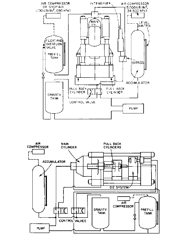
9.22 HYDRAULIC PRESSES 9.473
FIGURE 6 Vertical forging press with pull-back cylinders
FIGURE 7 Horizontal extrusion press

Intakes
AND
Suction
Piping
C•H•A•P•T•E•R•10

SECTION 10.1
INTAKES, SUCTION
PIPING, AND
STRAINERS
WILSON L. DORNAUS
CHARLES C. HEALD
10.3
The most critical part of a system involving pumps is the suction approach, or inlet,
whether in the form of piping or open pit. A centrifugal pump that lacks proper pressure
or flow patterns at its inlet will not respond properly or perform to its maximum capabil-
ity. Uniformity of flow and flow control to the point of pumped fluid contact with the
impeller inlet vanes are the most important. Part of this may be controlled by proper pump
design, but the pit designer and suction piping designer have definite responsibilities to
achieve satisfactory pump operation. In open suction pit (wet-well) designs, the fluid flow
must be as uniform as possible right up to contact with the pump suction bell or suction
pipe, preferably without a change in direction or velocity.
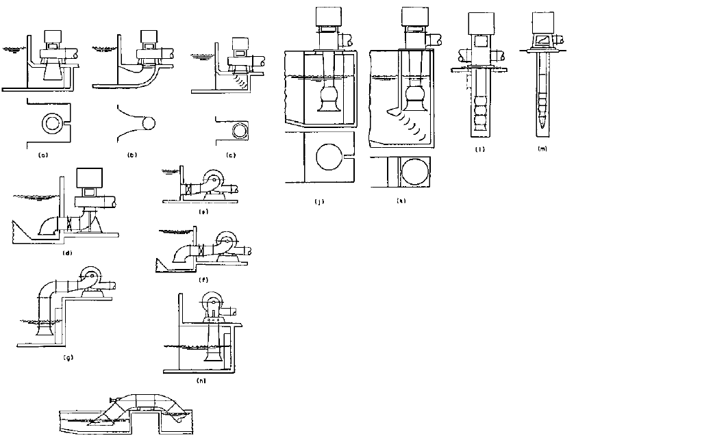
Examples of dry-pit and wet-pit centrifugal pumps connected to open suction pits are
shown in Figure 1.
In dry-pit pumping, the pipe leading to the pump suction flange should not include
elbows close to the pump in any plane. Also, any other fittings which change flow direction
and velocity and which may impart a spinning effect to the flow should be avoided within
8
–
10 pipe diameters of the pump suction flange. Centrifugal pumps not designed for pre-
rotation of the fluid entering the impeller, either dry or wet pit, may suffer loss of efficiency
and an increase in noise if a spinning inlet flow occurs. Fluid rotation with the direction of
impeller rotation can result in a decrease in pump developed head. Fluid rotation against the
direction of impeller rotation can result in an increase in pump developed head and required
power, possibly overloading the driver as well as drastically affecting the pump curve shape
and performance in the system. If the total system is to operate efficiently and with mini-
mum maintenance, close attention to the suction environment of the pumps is required.
INTAKE STRUCTURES ________________________________________________
Intake structures can be categorized as being for clear liquids or solids-bearing liquids.
For clear liquids, intakes are further classified into rectangular, formed, circular, and
10.4
FIGURE 1 Pump suction connections: (a–d) vertical dry-pit pumps. (a) Suction bell diameter and distance from
bottom, side, and back walls designed to provide radial inflow, equal velocity distribution, minimum entrance loss.
Proper spacing of bell and vertical baffle required to prevent underwater eddies and rotation at inlet. (b) To
minimize excavation under pump, decreasing-type suction elbow can be formed in the foundation. (c) Width of
suction inlet under pump minimized by use of turning vanes. (d) Smaller pumps provided with integral suction
elbows and can be connected to wet well with commercial piping. Flared suction elbow is turned downward to obtain
maximum submergence at inlet. Wet well sloped to suction inlet to prevent deposition of solids.
(e–i) Horizontal dry-put pumps. (e) Pump suction connected to larger pipe with eccentric reducer (double-suction
pumps only). Wet-well connection should be bell mouth of a size to provide minimum required velocity. (f) Flared
suction elbow turned downward for maximum submergence over inlet. Wet-well floor may be sloped toward inlet if
solids are present. (g) Vertical suction pipe with bell inlet adequately submerged to prevent vortexing. Bell sized and
spaced as in Figures 1a, h, and j. (h) Vertical suction pipe connected to bottom-suction pump. Bell sized and shaped
as in Figures 1a, g, and j. (i) Design used for drainage over levees. Suction pipe designed to require minimum
submergency and excavation. (j–m) Vertical wet-pit pumps. (j) Distance from bottom, side, and back walls designed
to provide equal velocity distribution, with splitter to prevent vortexing. (k) Width of inlet minimized by use of
turning vanes. (l) Canned suction pump with either above- or below ground suction connection. Can length
to suit NPSH required. Vertical installation minimizes excavation area. (m) Deep-well pump takes suction from
underground water source.
10.1 INTAKES, SUCTION PIPING, AND STRAINERS 10.5
trench types, as well as suction tanks and cans. For solids-bearing liquids, trench-type and
rectangular wet wells are usually considered. These structures are covered in detail in
American National Standard for Pump Intake Design, ANSI/HI 9.8-1998, Reference 1.
Further references to this standard will be contained in this section.
COOLING WATER PUMP INTAKES ______________________________________
Purpose
Water circulating systems must have either a continuously renewable source,
such as an ocean, lake, or river, or they must recirculate the same water from cooling ponds
or cooling towers. Regardless of the type of pump selected (wet or dry pit), the suction
water will come from an open pit of some sort or from a pressurized pipeline.
Types of Intake
ONCE-THROUGH: OCEAN, LAKE, OR RIVER SOURCE
—
WET PIT Once-through intake structures are
usually constructed of concrete and are arranged to gather the water into a localized area
for pickup and to support the pumps. The optimum design will bring relatively clear water
directly into the pump suction area at a low velocity.
It is recommended that the submergence of the pumps and the dimensions of the suc-
tion pit in the immediate vicinity of the pump suction inlet be as suggested by the pump
manufacturer. Preliminary intake drawings, however, must usually be prepared for mak-
ing studies and estimates and for writing specifications for equipment. During this pre-
liminary stage of intake design for vertical wet pit pumps (or for dry-pit pumps having
vertical suction pipe with a bell-mouth entrance), the recommendations found in the
American National Standard for Pump Intake Design, ANSI/HI 9.9-1998 (Reference 1)
should be followed. Figures 2 and 3 show the basic layout of the pumps and intake struc-
ture. Geometry is generally defined in terms of the pump inlet bell diameter, as shown.
Once the number and size of pumps required is determined, a pump inlet bell diameter
can be estimated. At this point, the bell diameter can be estimated based on an inlet pipe
velocity of between 3 and 8 ft/s (0.9 and 2.4 m/s). The resulting pipe diameter can then be
converted to a corresponding bell diameter approximately 1.5–2.0 times the inside pipe
diameter. With the bell diameter selected, the proportions of the inlet structure can be esti-
mated from Figures 2 and 3. Table 1 gives recommended values for the dimensions. For
establishing velocities, the minimum submergence over the suction bell for vertical wet-pit
pumps can be estimated from Figure 4, based on maximum expected flow rate.
Once the intake pump manufacturer has been selected, final intake dimensions can be
established on the basis of actual pump inlet pipe dimensions and the equipment sup-
plier’s recommendations. Should there be an appreciable variation in any of the dimen-
sions from various sources, a model test of the intake structure is justified and
recommended.
For further guidance, ANSI/HI 9.8-1998 (Reference 1) provides intake design recom-
mendations for both suction pipes and all types of wet pits that are a result of the com-
bined efforts of sump designers, hydraulic researchers, pump manufacturers, and end
users. It is intended to provide designers, owners, and users of pumping facilities a foun-
dation upon which to develop functional and economical pumping facility designs.
The intake design process is intended to arrive at a cross-sectional area such that
straight-line flow to the bell area is at an average velocity of 1 ft/s (0.3 m/s) or less. This
assumes the source to be either a lake or a river with a maximum velocity of 2 ft/s (0.6
m/s). For higher velocities, correspondingly greater distances should be used to the trash
rack or screen. The choice of providing a trash rack or screen, or both, is based on the type
and amount of debris likely to be encountered at the inlet.
An ocean inlet has additional requirements because of tidal action and variable direction
currents which may exist. For these situations, it may be necessary to create a forebay inlet
basin. Such a basin would be independent of the pump pit and fed by a submerged inlet
tube extending out into the ocean for some distance (Figure 5). This tube may utilize nor-
mal pipe velocities, but the inlet must turn upward and the opening should be protected by
a horizontal cap to allow the water to travel horizontally at a velocity high enough to scare