Pump Handbook by Igor J. Karassik, Joseph P. Messina, Paul Cooper, Charles C. Heald - 3rd edition
Подождите немного. Документ загружается.

10.26 CHAPTER TEN
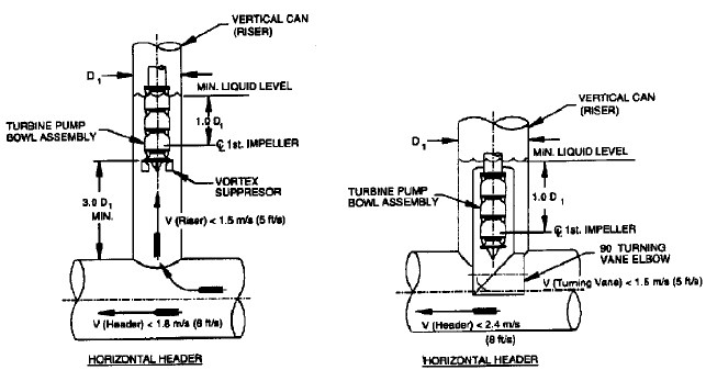
FIGURE 20 Open bottom can intakes for pumps less than 5000 gpm (315 l/s) (American National Standard for
Pump Intake Design, ANSI/HI 9.8-1998, Reference 1)
a) no turning vanes b) turning vane elbow
outlet fitting and direction of tank outlet flow and nozzles. If the tank has multiple inlets
or outlets, the design should be such that flow interaction is not detrimental to overall
performance.
CAN PUMP INTAKES__________________________________________________
A can pump is defined as one that has a can, or barrel, surrounding the pumping unit.This
can acts as a “sump” or intake structure for the pump suction impeller. The can may be
either closed bottom, and contain the pump suction nozzle, or open bottom and connect
directly to a piping header. The can design must provide uniform, stable flow distribution
to the suction impeller inlet.
Vertical turbine pumps (Figure 19) require uniform inflow to the suction bell to avoid
swirling and submerged vortices that may result in cavitation, vibration, and accelerated
pump wear. When a pump with an open bottom can design is connected to a horizontal
header (Figure 20a), the velocity in the header should be no more than 6 ft/s (1.8 m/s) to
allow the liquid to turn and flow upward to the pump suction bell. The velocity in the can
rising to the pump should not exceed 5 ft/s (1.5 m/s), and the suction bell inlet should be
located at least three diameters above the top of the horizontal header. For velocities
approaching the maximum recommended levels, vortex-suppressing vanes may be added
to the suction bell area to break up swirling and nonsymmetrical flow patterns as they
approach the impeller inlet.
If a 90 degree turning vane elbow on the can assembly surrounding the pumping
element is used (Figure 20b), the velocity in the horizontal header can be as high as 8
ft/s (2.4 m/s). The turning vane elbow should be sized for a maximum velocity of 5 ft/s
(1.5 m/s).
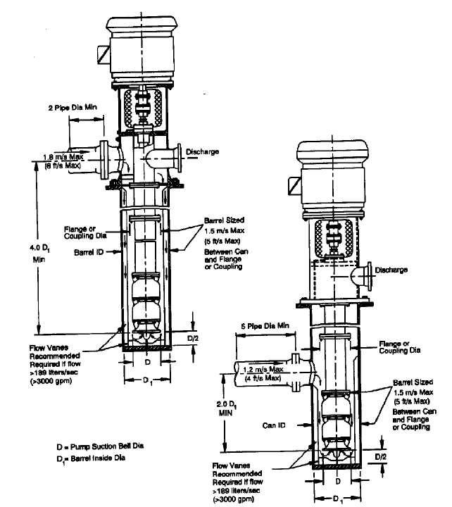
Most can pumps are of the closed bottom design (Figure 21). In this arrangement, the
pump suction nozzle is located either in the can or in the pump nozzle head that contains
both the suction and discharge nozzles. The pumping element (assembly) must be centered
in the can to avoid non-uniform flow to the suction impeller. Flow straightening vanes are
suggested for all can intakes. Because of the limited volume of liquid in the can, surging
of the liquid level within the can
—
or barrel
—
cannot be tolerated; the can should be
10.1 INTAKES, SUCTION PIPING, AND STRAINERS 10.27
FIGURE 21 Closed bottom can (American National Standard for Pump Intake Design, ANSI/HI 9.8-1998,
Reference 1)
arranged so it is always full. The velocity of the flow between the pumping element and
the inside of the can should not exceed 5 ft/s (1.5 m/s). For a suction nozzle velocity of 4
ft/s (1.2 m/s) maximum, the centerline of the nozzle should be at least two diameters
above the suction bell inlet. To ensure uniform flow distribution into the can, the suction
nozzle should be connected to at least five pipe diameters of straight pipe before elbows
or other flow-disturbing fittings are installed.
Pumps with submersible well-type motors require flow around the motor for cooling.A
shroud is typically used to direct flow across the motor as it goes into the pump. The top
of such a cooling shroud is covered to restrict downward fluid flow and still allow venting
of air from the shroud. This arrangement is described in detail in ANSI/HI 9.8-1998 (Ref-
erence 1). It is recommended that the inlet piping be sized to limit draw-down of the liq-
uid below the minimum required level during the startup to a period of less than 3
seconds.
10.28 CHAPTER TEN
SUCTION PIPING_____________________________________________________
Single Pumps
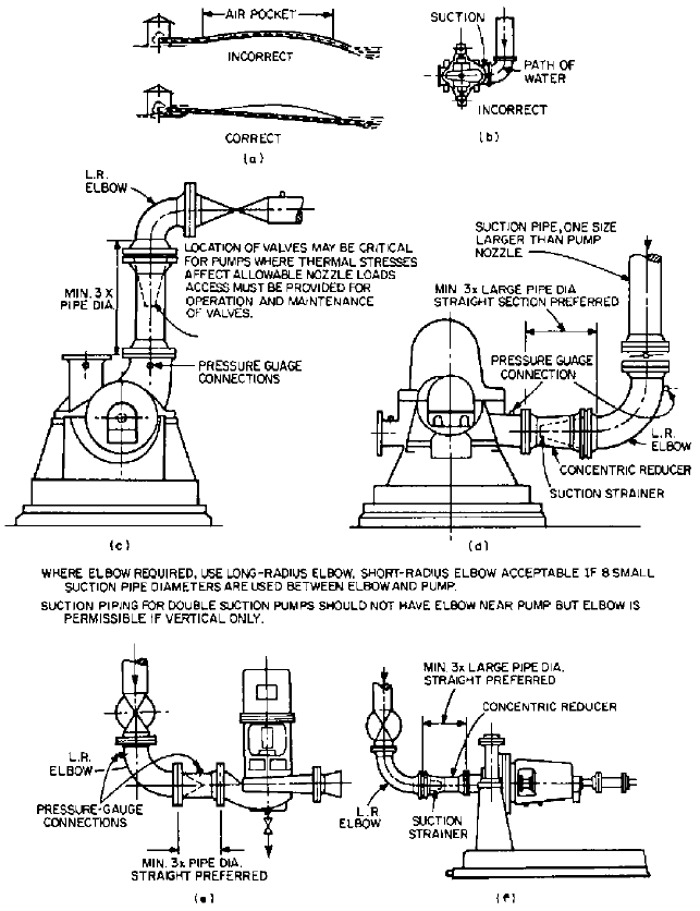
Piping to the suction of a dry-pit centrifugal pump (Figure 22) must be
carefully planned to provide uniform, straight-line flow to the impeller, and adequate pres-
sure and sealing against leakage, in or out. Air pockets just prior to entrance to the pump
should be avoided, as well as down flow lines subject to sudden pressure changes.Air pock-
FIGURE 22 Suction piping faults for dry-pit centrifugal pump. (a) Air pockets should be avoided.
(b) Suction elbow should not be in a plane parallel to pump shaft. (c) Valve location may be critical to pump nozzle
loading. (d), (e), Suction elbow should be one size larger than pump’s, long radius and three large pipe diameters
distant. (d), (f) Concentric reducer should be installed distant from pump.
10.1 INTAKES, SUCTION PIPING, AND STRAINERS 10.29
ets can be prevented by proper elevations (Figure 22a). Pressure surges can be controlled
by surge tanks, air tubes, and so on, which may require a system pulsation study to deter-
mine possible need and solution.
To provide an optimum flow pattern to avoid impeller disturbance, it may be neces-
sary to have a straight run of pipe of as much as eight pipe diameters immediately prior
to the pump suction (for example, following a short radius elbow or tee). Following a
long radius elbow or a concentric reducer, a straight run of at least three pipe diameters
is recommended (Figure 22c to f). Eccentric reducers should not be used next to the
pump suction nozzle. Although installing eccentric reducers with the flat side on top
will eliminate a potential air pocket, large changes in diameter could result in a dis-
turbed flow pattern to the impeller and cause vibration and rapid wear. Pipe venting,
in conjunction with a concentric reducer, may be preferable to the use of an eccentric
reducer.
Ideally, a suction pipe should approach a double suction pump perpendicular to the
shaft centerline. If there is an elbow in the suction piping upstream of the suction flange,
it should be bringing flow from either overhead or below, not from the side of the pump. If
there is a short radius elbow or other flow-disturbing device in the suction piping up-
stream of the suction flange, there should be at least five pipe diameters between the
device and the suction flange. If a short radius elbow is in the same plane as the impeller
shaft, there should be at least eight pipe diameters between the elbow and the suction
flange. An incorrect installation could result in an uneven flow to both sides of the double
suction impeller. This could cause a reduction in capacity and efficiency, an increase in
thrust on the bearing, noise, and possible cavitation damage to the impeller.
A dry-pit pump (Figure 1g) may operate with a suction lift and therefore will be located
above the liquid source. All losses in piping and fittings will reduce the available suction
pressure. Suction piping should be kept as simple and straightforward as possible. Any pipe
flange joint or threaded connection on the suction line should be gasketed or sealed to pre-
vent air in-leakage, which would upset the vacuum and keep the pump from operating
properly.
If expansion joints are required at the suction of a pump, an anchor should be inter-
posed between the pump nozzle and the expansion joint to prevent additional forces from
being transmitted to the pump case and disturbing rotating clearances. The same require-
ment applies to a sleeve coupling used to facilitate installation alignment.
Reciprocating pumps must have additional consideration because of the pulsating nature
of their flow. Suction piping should be as short as possible and have as few turns as possible.
Elbows should be long-radius. Pipe should be large enough to keep the velocity between 1
and 2 ft/s (0.3 and 0.6 m/s). This will generally result in pipe one to two sizes larger than the
pump nozzle. High points that may collect vapor are to be avoided or, if necessary, properly
vented. A pulsation dampener or suction bottle should be installed next to the pump inlet.
Available NPSH should be sufficient to cover not only reciprocating pump requirements and
frictional losses but also acceleration head (see “Surge and Vibration”).
Manifold Systems All comments relative to single pumps apply to manifold-pump sys-
tems, as well as some additional points.
In a suction manifold, the main-line flow should not be more than 3 ft/s (0.9 m/s).
Branch outlets should be at 30 to 45 degrees relative to main-line flow rather than 90
degrees, and velocity can increase to 5 ft/s (1.5 m/s) through a reducer (Figure 23). With
such velocities, branch outlets can be spaced to suit pump dimensions in order to avoid
crowding.Also, if the angled manifold outlet is used, pumps can be set as close to the man-
ifold as the elbow, valve, and tapered reducer will allow.
Manifold sections beyond each branch takeoff should be reduced to such a size that the
velocity remains constant. One exception to this scheme is a tunnel suction (Figure 24).
The flow through the tunnel may operate independent of the pumps, which are suspended
in boreholes drilled into the roof of the tunnel. Boreholes at least one-third of the tunnel
diameter should be horizontally spaced at least 12 borehole diameters apart. Smaller
ratios can be closer to a minimum of six diameters. Pump suction bells should be at least
two borehole diameters above the tunnel roof. Velocities in the tunnel should be kept below
8 ft/s (2.4 m/s) for best pump performance.

10.30 CHAPTER TEN
FIGURE 23 Suction pipe header recommendations for dry-pit centrifugal pump
FIGURE 24 Higher tunnel velocities require isolation of pump from direct flow to prevent distortion of close-
clearance parts and shaft (Hydraulic Institute Standards, 13th Edition, 1975—out of print)
NPSH The net positive suction head so essential to trouble-free pump operation is
always reduced by losses in suction piping. An economic balance must be obtained
between pump size and speed, required NPSH, pipe size, and suction velocity. If the suc-
tion source is a tank, such as a deaerator in a power plant, it is quite expensive to ele-
vate the tank. Therefore, the available NPSH is low. The pipe size from the tank to the
pump should be large for low velocity and the length should be short for minimum losses.
A cooling tower on a hill supplying water to a pump station below could have a much
higher pipe velocity and longer length without forcing an extremely low NPSH require-
ment on the pump.
A dry-pit pump should be as close to the suction source as possible. When the NPSH
required indicates a suction lift is possible, the most advantageous solution is to reduce the
suction losses by increasing the pipe size, flaring the inlet bell, and keeping the pump suc-
tion eye of the first-stage impeller close to the minimum water level.
High-Pressure Inlets Pumps in series build up pressure, so the second and following
pumps will have a high-pressure suction piping connection. This emphasizes the need for
tight joints and flanges and careful welding. Expansion joints should not be used because
the hydraulic forces on the pump would be large, difficult to restrain, and perhaps impos-

10.1 INTAKES, SUCTION PIPING, AND STRAINERS 10.31
sible for the pump to handle without distortion. As NPSH will not be a problem for pumps
downstream of the first pump, the pipe size between pumps can be kept small to mini-
mize design problems and valve costs.
Effect on Pump Efficiency Other than mechanical operation, the greatest effect of flow
disturbance at the pump suction is on pump efficiency. The higher the pumping head, the
lesser this effect becomes. For very high-head pumps, a high velocity may be ignored com-
pletely unless there is an extremely large power evaluation factor. Greater attention
should be given to the suction pipe design for pumps producing 100 ft (30 m) of head or
less than those with high head, as efficiency may be worth many dollars in power costs
over the life of the plant and equipment.
Pump efficiency relates to the efficiency of the whole system, and so it may be well
worthwhile to invest more money in a large suction pipe.
Surge and Vibration One of the possibilities arising from a power failure at a pump
station is the reversal of a centrifugal pump if a valve fails to close, and its subsequent
operation as a turbine. Under rated head, a pump will run from 20 to 60% above rated
speed in the reverse direction. In its transition to that phase, the forward motion of the
water is interrupted and gradually reversed. At the time of the power failure, the flow
velocity in the suction pipe may not decelerate slowly enough to prevent a surge in the
direction of the pump. The suction piping should be designed to withstand the resulting
pressure rise because absolute integrity of valving and power supply will be too costly as
a design parameter (see Chapter 8 for additional information on this subject).
Rotating machinery must have a design vibration frequency that is sufficiently
removed from a system frequency to avoid sympathetic activity. Any combination of
vibration frequencies near enough to each other to react will do so when a prime source,
such as a pump, excites them. When a piping system has been designed to allow only very
low stresses to be transmitted to a pump nozzle, it is quite vulnerable to vibration. It is
usually good practice to analyze a suction system made up of pipe, valves, hangers,
restraints, pump nozzle loads, pump speed and impeller configuration, foundation, and
anchors to be sure the system is not “in tune.” At the design stage, it is relatively easy to
change a valve or elbow location or to add a surge suppresser. It is usually much more
costly to change a pump.
Reciprocating pumps are surge producing machines. In particular, they require suffi-
cient energy at suction to overcome pump required NPSH and pipe friction and a form of
energy called acceleration head. The pump energy must overcome the acceleration-
deceleration pulsation flow in the suction end, which could lead to liquid flashing with
pump noise and vibration. Surges large enough to rupture the pump cylinders may also be
produced.
The total NPSH required by a reciprocating pump must include the NPSH required by
the pump plus frictional loss from the suction pipe plus acceleration head. Acceleration
head in feet (meters) is
where L actual (not equivalent) length of suction pipe, ft (m)
V velocity of flow in the suction line, ft/s (m/s)
N pump speed, rpm
C pump constant, decreasing with number of cylinders from 0.2 to 0.04
g acceleration of gravity, 32.17 ft/s
2
(9.807 m/s
2
)
K liquid constant: 2.5 for compressible fluids, 1.5 for water
The acceleration head can be reduced by installing a pulsation dampener in the suction
line near the pump.
Ha
LVNC
gK
10.32 CHAPTER TEN
PIPE SCREENS AND STRAINERS_______________________________________
Except for special designs for handling slurries and other solids, most pumps are limited
in their ability to handle dirt, trash, and solids of any size down to microparticles. Pump
passageways (volutes, diffusers, impellers) handle generally spherical objects up to a
“sticking size,” but a severe problem may be caused by dust-size particles that lodge in
sleeve bearings, bushings, and wear rings and cause either rapid wear or rotation seizure.
A wet-pit source may never be quite free from some degree of silt or sand. After it is
accepted by the pump, this liquid goes into a piping system, usually one with other pumps
involved. The original pit pump may also be a dry-pit type. In either case, if the pumps of
a system are to operate for long periods of time with minimum maintenance, wearing
parts must be protected by fine screens or strainers.
In any screening operation, it is essential to remember that if the screen is necessary
and does a good job, it will plug up and thus requires cleaning. In a wet pit, therefore, nei-
ther the suction bell of a wet-pit pump nor the suction bell going to a dry-pit pump should
be basket-screened. Collection of debris will soon increase inlet velocity to unmanageable
proportions, and the pump operation will suffer.
It follows that if the basic screening discussed previously does not provide liquid clear
enough to be pumped, additional strainers must be put into the system. The need for
such strainers, and the degree of particle reduction, are usually specified by the pump
manufacturer. In some instances, the system may require water as pure as it is possible
to produce, as in boiler-feed service. For any situation, a variety of strainers is available.
Drum rotating strainers (Figure 12) can handle solids as small as approximately 0.01
in (250 mm). Backflushing is used to renew the strainer area. The addition of woven wire
cloth (Table 2) to such strainers may remove materials down to 0.1 in (25 mm).Woven wore
drum strainers used in conjunction with sand filters will reduce the amount of backflush-
ing required for the sand filters.
Where a finer degree of filtration is required, a line filter is used. Single flow filters
require system shutdown to remove and clean baskets, but either a motorized automatic
type of single flow filter (Figure 25) or twin filters with alternate flow by valve arrange-
ment (Figure 26) permit uninterrupted system operation.When a particularly difficult sit-
uation exists, a battery of filters in series may be used.
For areas where wear can be extremely critical, such as bearings and stuffing boxes
(mechanical seals), additional filtering is necessary, especially if the entrained silt is abra-
sive. A vortex filter using centrifugal flow action will remove particles down to a few
micrometers. These filters have continuous sediment removal and should not require any
maintenance (Subsection 2.2.1, Figure 78).
Some systems, such as boiler feedwater, are “closed” after they are in an operating cycle.
Chemical and mechanical cleaning components are designed into the system to obtain a high
degree of water purity. Before the system is ready to operate, however, the piping, tanks,
valves, and so on, will have a residue of weld spatter, metal chips, and other debris from the
fabrication process. Temporary strainers are used in the suction lines of boiler feed pumps
and condensate pumps to gather up this debris.These strainers are in-line fabricated metal
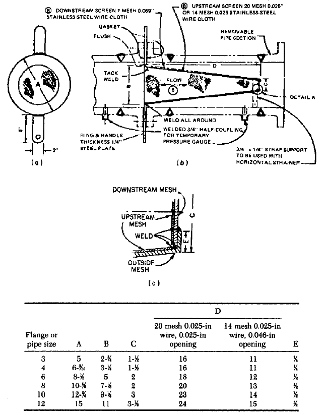
mesh of either a cone or box type. Feed pumps are most often equipped with cone strainers,
pointing preferably upstream (Figure 27).The length and diameter are set to conform to the
suction pipe size and the mesh so the velocity does not become excessive.These strainers,set
between flanges in a pipe section, must be removed and cleaned whenever the differential
pressure reaches 2
—
3 lb/in
2
(15 to 20 kPa). Condensate pump strainers are usually box
strainers, a square section directly in front of the suction flange with a square box larger
than the pipe diameter laced with egg crate metal mesh (Figure 28).This basket strainer can
be lifted out of the box for cleaning as necessary. These strainers for collecting fabrication
debris may be removed when the need disappears and the system will remain clean.
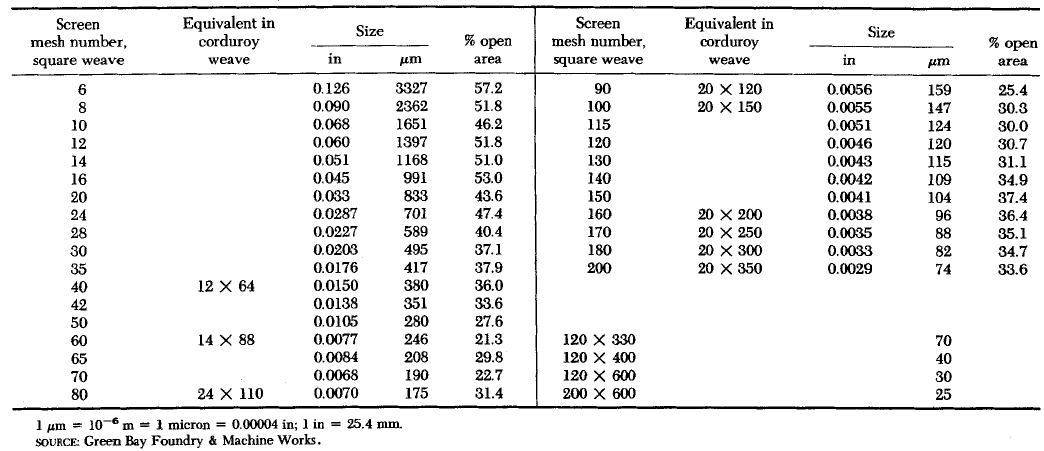
10.33
TABLE 2 Wire mesh data
10.34 CHAPTER TEN
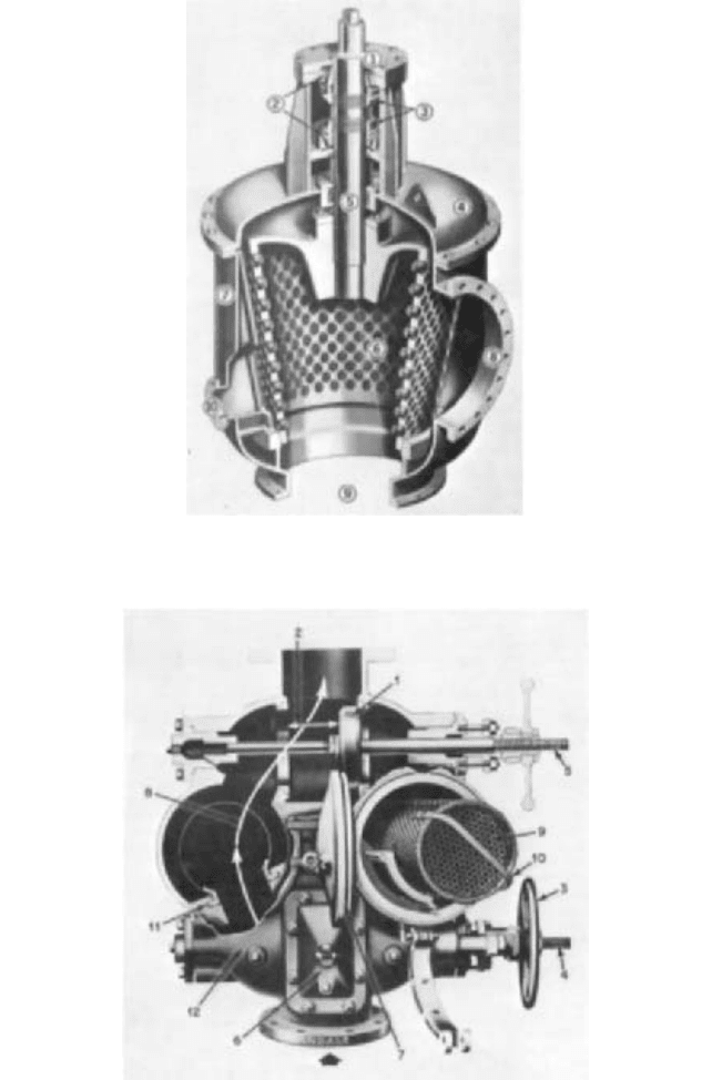
FIGURE 25 Single flow strainer with provision for backwashing without interrupting service: (1) strainer drive,
(2) strainer drum support bearings, (3) lock nuts for drum adjustment, (4) cover, (5) shaft, (6) drum—tapered for
adjustment, (7) body, (8) inlet, (9) outlet, (10) backwash opening (S. P. Kinney Engineers)
FIGURE 26 Duplex basket strainer. Flow through one side allows cleaning of opposite basket while line is still in
service. (1) positive flow diversion, (2) rapid switchover, (3) free-turning handwheels, (4) visual indication of valve
position, (5) external acme threads, (6) internal access, (7) cover and clamp(s), (8) streamlined flow, (9) basket, (10)
basket handle, (11) basket, (12) one-piece body construction (Andale)
10.1 INTAKES, SUCTION PIPING, AND STRAINERS 10.35
FIGURE 27 Cone strainer for start-up service in boiler-feed pump system. (a) cross-section, (b) lengthwise
section, (c) typical detail A (nose pointing downstream). All dimensions are in inches (1 in = 0.0254 m = 2.54 cm).
Strainer ring material is carbon steel. When a strainer has served its purpose, the screen portion is removed, the ID
of ring is cut to suit ID of pipe, and the ring is used as a spacer. Cone strainers may be installed with nose pointing
either upstream or downstream. The fine mesh screen should always be on the upstream surface of the strainer.