Pump Handbook by Igor J. Karassik, Joseph P. Messina, Paul Cooper, Charles C. Heald - 3rd edition
Подождите немного. Документ загружается.

11.2 CHAPTER ELEVEN
STEPS IN THE PROCESS ______________________________________________
After the initial decision that pumping equipment is required, purchasing of the equip-
ment can be divided into the following general steps.
• Engineering of the pumping system
• Selection of the pump and driver type
• Pump specification and data sheet preparation
• Inquiry and quotation
• Evaluation of bids and negotiation
• Purchase of the selected pump and driver
In the process of specifying pumping equipment, the engineer must determine system
requirements and system head curves, select pump type, write the pump specification,
complete the pump data sheet, determine testing, inspection and vendor drawing and data
submittal requirements and develop all the data necessary to define the required equip-
ment from the supplier.
Having completed this phase of work, the engineer is then ready to take the steps nec-
essary to purchase the equipment. These steps include issuing the pump inquiry to the
bidders, technical and commercial evaluation of pump bids, selection of the supplier, and
release of data necessary to issue the purchase order. The ultimate result of this process
is the selection of a pump/driver combination that satisfies both the process and mechan-
ical requirements.
ENGINEERING OF PUMPING SYSTEM REQUIREMENTS ____________________
The first step is to define the requirements and conditions under which the equipment will
operate.
Fluid Type A thorough description of the fluid to be handled must be developed. This
includes properties such as viscosity, density, vapor pressure, corrosiveness, erosiveness,
volatility, flammability, and toxicity. Depending on the process and the system, some or
all of these properties may have an important effect on the pump and system design. For
example
• The corrosiveness of the fluid will influence the materials of construction.
• If the fluid contains solids in suspension, suitable types of pump seal designs and
abrasion-resistant pump construction must be considered.
• Erosion due to high particle content may cause premature performance decline. Large
particles may favor open impeller design.
• Fluid toxicity may necessitate the use of dual (tandem or double) mechanical seals due
to government regulations or safety considerations.
• Entrained gases may affect the pump’s ability to produce the required differential
pressure.
The specified fluid physical and chemical properties must cover the entire expected
operating range of the pumping system. Influences such as varying temperatures and
pressures must also be defined.
System Head Curves The engineer must have a clear understanding of the process
and system in which the pumping equipment will operate. A preliminary design of the
system should be made and should include an equipment layout and a P&ID (piping and
instrument diagram). These preliminary drawings will show the various fluid flow paths
11 SELECTING AND PURCHASING PUMPS 11.3
for system operation, preliminary pipe diameters and lengths, relative elevations of sys-
tem components and all valves and other piping components that will be used to estab-
lish the system head losses. These drawings will be used by the engineer to calculate the
final piping sizes and pumping system head requirements.
With this information, the engineer can develop system head curves that show the
relationship between flow rate and hydraulic losses in the piping system. In determining
the hydraulic losses, the engineer must include adequate allowances for future corrosion
and scale deposits in the piping system over the plant life.
Because hydraulic losses are a function of flow rate, pipe size, and layout, each indi-
vidual flow path alignment in a given system will have its own characteristic operating
curve. Care must be taken when specifying the required pump characteristics to take into
account all possible system operating flow paths. It is convenient to add the effects of sta-
tic pressure and elevation differences in the system to form a combined system head curve.
This combined curve shows the total head required of the pumping equipment to overcome
system resistance as well as differential static pressure and elevation. The pump head
must be at or above the combined system curve at all required operating points and fluid
conditions for the various system flow paths. Refer to Sections 8.1, 8.2, 9.1, and 9.2 for
guidance in constructing system head curves.
Modes of System Operation System operating modes are important considerations
when specifying pumping equipment. Will the pump be used in continuous or intermit-
tent operation? Will the pump operate in parallel or series with other pumps? Will there
be significant differences in head or flow rate requirements in different system align-
ments? Will a single pump be used as a common spare for two different pumping appli-
cations? These and other questions arising from analyzing the different modes of
operation will help influence decisions as to the number of pumps needed, heads and
capacities and whether booster pumps are desirable in some system alignments. It should
be noted that unnecessarily conservative hydraulic requirements may increase pump com-
plexity (such as the selection of a more elaborate multistage or double suction pump in
place of simpler single stage, overhung pump) and cost.
The engineer should also consider the length of time between plant maintenance
expected of the pumping system. This factor will influence the decision of quantity, pump
type, requirement for installed spare(s), and the manufacturing quality required of the
specified pumps. Frequently, due to the critical nature of a pumping service where high
reliability is necessary, installed spares are provided. In some cases, 2
—
100% pumps are
provided. When system flowrate requirements fluctuate, 3
—
50% pumps may be called for.
When reduced flowrates will not adversely affect operations, 2
—
50% pumps can be speci-
fied. Plant operating philosophies will dictate if automatic start of a spare pump is
required.
Pump Flow/Head Margins Pumps are normally specified with a capacity margin above
what has been determined necessary for the process. In addition, the calculated system
head losses are also determined conservatively. The reasons for this include the following:
• During system design, many assumptions are made while determining pump require-
ments, some of which might eventually be determined to be incorrect.
• During the plant life cycle, process conditions are likely to change due to aging catalyst,
changes in feed stock, seasonal feed temperature variations, and so on.
• Final piping design may be significantly different from preliminary design.
• System hydraulic losses may change due to corrosion, and so on.
During preliminary system design, these potential future changes in head/capacity
must be studied to determine the required design margin. Because a pump should be
selected to operate close to its best efficiency point, it is important to minimize the selected
margin. Margins of 5 to 10% on flow are typical but even 20% is common, for example, in
reflux tower service. In cases where the process is well proven and understood, and system
operating requirements are well defined, a zero margin is sometimes appropriate.
11.4 CHAPTER ELEVEN
Plans for future capacity increase may be foiled if the piping system does not provide
for adequate net positive suction head at the future flow conditions.
Care must be taken when applying margins to ensure that the purchased pump is not
oversized. If the total head produced is too large, impellers may be trimmed within the
allowable range of the pump model provided. If the flow is significantly oversized, a costly
energy penalty can result over the life of the plant. This is caused by lower pump operat-
ing efficiency at off-design flow rates and discharge throttling losses that may be neces-
sary to control the flow rate to the desired value.
Type of Pump Control The type of control for the required pump is also an important
consideration for pump specification and selection. Since the actual piping system usu-
ally incorporates a design margin, a control valve is normally employed in centrifugal
pump applications. This control valve (not supplied by the pump manufacturer) is used
to adjust the system curve over the life of the unit. Flow sensing control provides the most
stable operation for most systems. Pressure control can have very large swings in flow
when operating in a flat or drooping area of a centrifugal pump curve. For this reason,
most centrifugal pump specifications incorporate the requirement for the centrifugal
pump operating curve to rise continually to pump discharge valve shut in (also known as
the pump shut off).
Both temperature and level sensing control can lead to a pump running at shut off or
at the end-of-curve condition during upset or failure modes. Centrifugal pumps with a 10%
to 20% head rise between the specified operating point and the shut off point may be pre-
ferred for some services such as for parallel pump operation.
Pumps that may operate in the shut off condition may need a continuously open bypass
to prevent pump damage. Pump manufacturers will advise of the minimum required flow
for an offered pump, but many end users require an additional margin above the manu-
facturers recommended minimum flow. If a continuous flow bypass is incorporated in the
system design, this additional flow must be added to the specified pump requirement.
Refer to Section 2.3.4 for bypass designs.
Future System Changes A final factor to be considered is the possibility of providing
for future system changes. When future system changes can be predicted with a degree
of certainty, the system can be designed with this in mind. Rather than selecting a pump
that is operating at the high end of its preferred operating region, a larger impeller diam-
eter or the next larger size pump operating at the beginning of its preferred operating
range might be considered. In addition, the capability for installing a larger diameter
impeller to handle future higher head requirements must be considered. Because mini-
mizing capital costs for a project is usually the prime consideration, oversizing a pump
for future operations is not normal practice. Pumps are expected to operate efficiently and
reliably in the present system, and this fact should be noted during the selection progress.
SELECTION OF PUMP, DRIVER, AND AUXILIARIES ________________________
As stated previously, the selection of pump type for a particular application is influenced by
such factors as the fluid characteristics, required materials of construction, system flow/head
requirements, intended equipment life, energy cost, and availability of certain utilities, such
as cooling water. Accuracy in these areas is critical for proper selection of pumps.
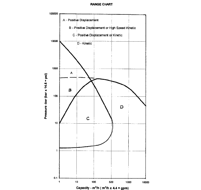
Pump Types There are several different types of basic pump designs. Each design can
be used for a range of flow and head combinations. Figure 1 gives a general overview of
the type of pump that can be used for various heads and flow rates.
In addition to capacity and head considerations, other operating characteristics of a
pump will help the engineer to select a pump type for a given application. Some of the con-
siderations are detailed in the following sections.
Self Priming Requirement If a pump is taking suction from a source below the pump
suction nozzle, a self-priming capability may be necessary. Positive displacement pumps
11 SELECTING AND PURCHASING PUMPS 11.5
FIGURE 1 General pump overview
such as a piston pump or a rotary screw or gear pump are able to self-prime within lim-
its in the smaller capacity range.There are also special centrifugal pump designs that will
self-prime in this situation.
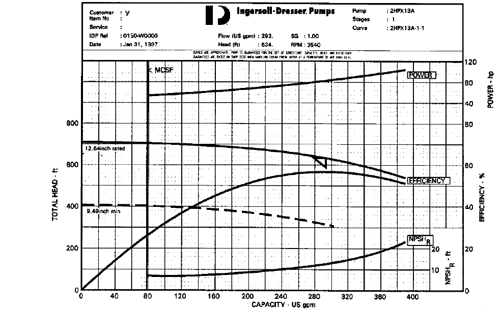
Variable Head/Flow Requirement Centrifugal and axial flow pumps are able to oper-
ate in variable head/flow conditions. By reviewing the pump curve for a given pump, the
head/flow range capability for these types of pumps can easily be determined. Refer to cen-
trifugal pump operating curve, Figure 2. For a specific impeller size, a centrifugal pump
will produce any flow rate within its head-flow rate characteristic curve which corresponds
to the system head curve (see Figure 2), if sufficient NPSH is available. The system head
characteristics can be changed to vary the flow by discharge throttling or by varying pump
speed.
High Head Required (Above Single Stage Centrifugal Pump Ability) Depending on
the required flow rate, either a centrifugal or a piston pump may fulfill the need for high
differential head. If a relatively small flow is required, either an integrally geared high-
speed centrifugal pump or a piston pump may be applied. When selecting between these
two choices, other questions to ask might be
11.6
FIGURE 2 Typical centrifugal pump characteristic curves versus flow rate or capacity. (m
3
/h = 0.277 gpm; m = 0.305 ft; kW = 0.746 hp) (Flowserve Corporation)
11 SELECTING AND PURCHASING PUMPS 11.7
• Will the pulsating flow of a piston pump be detrimental to system operation? Will a
pulsation dampener take care of this problem?
• Is the liquid clean enough to avoid premature wear on pistons and cylinders?
For high flow and high head combinations, a multi-stage centrifugal pump can be used.
Various designs of this type of pump are available with a wide range of prices reflecting
special designs for a whole range of applications (high temperature, cryogenic, water,
hydrocarbon, and so on).
Low Flow with Precise Flow Adjustment Ability For low-flow applications where
accurate flow metering is necessary, a proportioning pump is appropriate. This type of
pump can also be provided with variable flow capability. Certain types of gear, plunger,
and diaphragm pumps can also be used in combination with a variable speed drive for
flow rate regulation.
Low Available Net Positive Suction Head If the available net position suction head
(NPSHA) is low, specially designed centrifugal pumps can be considered. Depending upon
how low the NPSHA is, either a horizontal end suction with a suction inducer or a hori-
zontal double suction arrangement may be applied. A vertical turbine pump may also be
used, either immersed in the process fluid (possibly in a tank or vessel) or in a specially
designed vessel (known as a suction can) that can be installed below grade to increase
the NPSHA.
Code and Industry Standard Requirements The design, construction, rating, and
testing of most pumps used in refining and chemical industries are governed by standards
such as API (American Petroleum Institute), ASME (American Society of Mechanical
Engineers), the Hydraulic Institute, NFPA (National Fire Protection Association), PIP
(Process Industry Practices), ISO (International Organization for Standardization) and
various other international standards. The severity of the service in which the pump will
be applied, as well as the location of the plant, will determine which industry standard
(or standards) will be used, if any.
In the case of a fire pump service, NFPA compliance might be mandatory to meet the
user’s insurance company requirements. If a pump will be installed in an oil refinery or
chemical plant, either API or ASME standards will be applied depending on the severity
of the service and client preferences. International standards such as DIN (German), BS
(British), JIS (Japanese), or ISO can also be used. These standards are intended to provide
a pump with a level of quality to match the needs and expectations of the end user of the
equipment. It is obvious that the quality requirement for an emergency feed water pump
in a nuclear power plant needs to be much more stringent than a potable water booster
pump in an office building. The quality issues covered by these codes/standards ranges
from detailed design issues to inspection and performance testing requirements.
Fluid Characteristics Fluid characteristics such as viscosity, density, vapor pressure,
volatility, chemical stability, solid content, and entrained gases are important factors to
be considered for proper pump selection. Pumps are available to handle a full range of
fluid types. A positive displacement progressing cavity pump can be used to pump tooth-
paste, peanut butter and shampoo, but it will not usually be a good choice for pumping
water or gasoline. A rotary, variable displacement piston pump is a good choice for a
hydraulic control system, but not for a potable water application. A rotary sliding vane
pump can be successfully applied for pumping hot asphalt and for limited application in
a lube oil system.
Making the best pump selection for a certain fluid application is often difficult. Previ-
ous successful experience is usually the best guideline for proper pump selection. This
information can be obtained from end users, from process licensers, and from pump man-
ufacturers. Recommendations from all of these sources should be carefully considered.
Pump Materials Material selection is affected both by the pumped fluid and the envi-
ronment. Resistance to corrosion and erosion are of prime importance. The engineer must
11.8 CHAPTER ELEVEN
determine which material is most suitable and economical for a particular service. This
requires that an evaluation be made comparing the more expensive longer life material
to a less expensive material, which may provide a shorter pump life. Requirements such
as continuous or intermittent operation, critical or non-critical service and plant life cycle
should be considered when selecting materials.
Pumps are commonly available in cast iron, ductile iron, bronze, carbon steel, alloy
steels, and in some cases composite materials or special alloys such as Monel, Hastelloy,
or Titanium. In addition to the importance of pump design life, safety must also be con-
sidered when selecting materials. Cast iron construction is not used for pressure casing
parts of pumps that are to handle flammable or hazardous liquids because cast iron is brit-
tle and subject to fracture when thermally shocked. For these services, pressure-casing
parts must be high strength ductile materials such as carbon or alloy steel.
Driver Selection The choice of driver type for a pumping service is as important as the
pump selection. Factors that affect the driver choice are capital cost, driver type avail-
ability, operating reliability and the availability and cost of utilities.
Constant speed electric motors are most economical when only the first cost is consid-
ered. Often there is excess steam available within a facility that, when compared to the
cost of electricity, will justify the extra cost of a steam turbine. Reliability requirements
may necessitate the use of both a steam driven main pump and an electric motor driven
back-up pump. In the case of firewater pumps, a battery-start, diesel-fueled internal com-
bustion engine is needed to be completely independent of plant utilities. More expensive
variable speed electric motors can sometimes be justified if the pump is operated well
below its design conditions and there is the potential for significant savings in power.
There are other factors that should be considered when selecting the pump driver. The
capital cost as well as the installation cost is more expensive for a steam turbine due to
required piping. Steam turbines also require more maintenance during plant life, which may
be undesirable to the owner. Selection based on past proven performance and selection to
match existing plant equipment to minimize spare part inventory is a common consideration.
Air-operated diaphragm-type pumps are available in relatively small capacities, and
these can be particularly effective in hazardous area classifications where use of electric
motors may be undesirable.
Other Equipment Supply Decisions For both technical and commercial reasons, the
purchaser may decide to purchase the pump/driver combination in various ways.
The pump and driver may be purchased separately. This may be advantageous if either
the pump or driver (but not both) can be purchased locally. This will save shipping costs
and possibly allow the purchaser to meet client requirements for locally manufactured
content for a project. Separate purchase of drives on large capital projects can also lead to
quantity price discounts and limited spare part inventories.
The purchaser must consider the risk associated with the separate purchase of the
pump and driver. Equipment installation and alignment problems (with resulting start-up
delay) are more probable than when the pump vendor takes single source responsibility
for the purchase and skid mounting of all components.
If the decision is made to purchase the driver separately from the pump, the pump
manufacturer can provide the equipment for block mounting or provide a skid on which
the driver can be installed in the field. Either way, additional shop inspection is recom-
mended to verify dimensions for field interface. It should be noted that pump manufac-
turers may purchase a high volume of electric motors and obtain greater discounts than
most operating companies and engineering contractors.
PUMP BID REQUISITION ______________________________________________
It is obviously necessary to fully define the scope of supply for the desired piece of equip-
ment. To do so requires the right amount of documentation provided by the purchaser (no
more, no less) to match the type of equipment being purchased. This is easier said than
11 SELECTING AND PURCHASING PUMPS 11.9
done, but the engineer needs to be conscious of the fact that a bid requisition package
should be clear and concise as possible. One industry joke relates the cost of a piece of
equipment to the weight of the paper included in the bid requisition.
Requisition A bid requisition is a document that requests a vendor or series of vendors
provide a quote for a specified item. This can also be called an inquiry or request for quo-
tation or simply an RFQ.
The bid requisition can be as simple as a one-page listing of the pump requirements. It
can also be a document that incorporates data sheets, technical specifications, shipping
specifications, purchasing terms and conditions, vendor drawing requirements, and any
other document that will help define the full requirements of the intended purchase. A
fully detailed requisition for a complicated pumping service might include over 100 pages
of requirements.
As a minimum, the requisition must include a clear scope of supply, applicable specifi-
cations and data sheets, and commercial terms and conditions. In addition, the requisition
can be used to specify additional requirements that have not been adequately addressed
in other documents.
Commercial Terms and Conditions The requisition should include the following com-
mercial terms and conditions:
• Name of buyer, place to which proposals must be delivered, information on ownership
of documents, time allotted for submission of bids, governing laws and regulations
• Location of plant site
• Site storage conditions and anticipated length of storage (preparation requirements)
• Schedule for submittal of drawings/documentation, and pump delivery
• Guaranty/warranty requirements
• Instruction on minimum information to include in the proposal, number of copies that
vendor must provide, status of alternative offerings, and a statement on the owners
right to accept or reject bids that are not in accordance with the bid package
• Acceptable terms of payment
• Method of transportation to site that establishes the vendor’s responsibility. If the ven-
dor will not be responsible for providing shipping, he must be requested to provide
enough information in the quote for others to estimate shipping costs
• Customer shop inspection requirements
• Any penalty or bonus related to late or early shipping, and so on
The list of specifications and data sheets must include document name or descrip-
tion, document number, revision number, and revision date.This will provide a record of
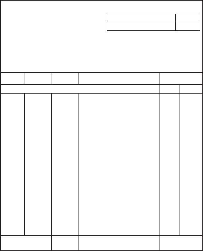
what documents have been sent to a vendor. See Figure 3 for an example of a requisi-
tion format that might be used to request bids for pumps in an oil refinery or petro-
chemical plant.
Pump Technical Specification As discussed previously, there are many different
designs of pumps that can be purchased. Engineering and operating companies may have
standard technical specifications for all categories of equipment that are commonly pur-
chased. When a pump service is being prepared for bids, a technical specification can be
used in standard form, or updated to incorporate special requirements based on client or
other project specific needs.
A technical specification is usually written to cover a wide range of equipment within
a given category. Because many variations exist within any equipment category, the tech-
nical specification is usually written to be applicable to this range of equipment. Data
sheets may be used to provide the specific requirements not covered in the technical
specification.
Most technical specifications are written as performance specifications rather than
design specifications. Care must be exercised to ensure that the pump manufacturer (not
11.10 CHAPTER ELEVEN
FIGURE 3 Example of a requisition format
REQUISITION
Type of Order:
Client:
Plant Location: Technical Review Required:
Level of Technical Data Sufficient for: P.O. #:
Vendor Inquiry Vendor:
Place Purchase Order
Line Ref Item No. Quantity Material & Attachment Description Budget
Unit Extension
Originator Ext. Approved By: Total Budget (US)
Requisition Number Rev. No.
the purchaser) is responsible for the actual equipment design. If design requirements
rather than performance requirements are specified, the vendor may claim that he is not
responsible when performance requirements are not met. Care must be taken to assure
that the equipment selected is from qualified vendors with proven design experience in
similar applications. The purchaser must resist the temptation to force the vendor to
modify a proven design and build a pump with which the vendor does not have proven
experience.
As a minimum, a technical specification must list the following:
1. Industry codes and standards to which the pump must be designed, constructed, and
tested. It is also possible to create a technical specification that stands alone and does
11 SELECTING AND PURCHASING PUMPS 11.11
not reference (or minimally references) codes and standards. This stand-alone
technical specification will require a more thorough listing of needed requirements
than one that references common design, fabrication, and testing standards.
2. A list of desired deviations and preferences from the main technical standards used to
help define the pump requirements.
3. A definition of any technical terms used in the specifications that are not defined in
referenced standards. This will help prevent misunderstandings between the pur-
chaser and pump vendors.
4. A list of documents to be submitted by the successful bidder, both with the quotation
and after the order is placed.
Pump Data Sheets As stated previously, a data sheet is used to list specific require-
ments for each individual pump service. These requirements are not general enough to
be listed in the technical specification. Each pump service requires its own data sheet. As
a minimum, the following items must be included on the data sheets for each service:
1. Pump name and item number
2. All required system design conditions and pump performance values needed to fully
define the pump operating requirements, including any known turndown, start-up, or
upset conditions
3. Materials of construction (unless the vendor is free to recommend standard materials)
4. All accessory requirements (unless the vendor is free to offer the standard selections)
such as driver, coupling, seal, and packaging needs
5. Utility conditions available
6. Intended site location and annual environmental conditions in this location
7. Electrical hazardous area classification
8. Instrumentation and control requirements (usually out of the vendors scope)
9. Noise requirements
10. Any specific preferences that deviate from requirements of the technical specifications
11. Inspection and testing requirements
In addition, the vendor should be advised to fill in the applicable blanks in the data
sheet and submit the proposal. The manufacturer’s data will help define the offering. See
Figures 4a to 4e for the API-610, 8th edition, data sheet.
Other Requisition Documents and Requirements A purchaser may include many
additional options in the bid requisition. These requirements may be included in the req-
uisition narrative or data sheets. Some possible options are addressed in the following
paragraphs.
Alternates It is extremely difficult for a specification to cover all possible pumps
offered by various manufacturers. In addition, the pump industry constantly updates
their products due to competition and revisions to industry standards. Because of this,
it is good practice to allow manufacturers to offer alternatives to the specified pump-
ing equipment. This allows manufacturers to present their best offerings and gives the
purchaser the advantage of obtaining commercially and technically attractive alter-
nate offerings. However, the choice of whether to accept an alternative is retained by
the purchaser.
Energy Evaluation The purchaser may choose to include operating costs in the equip-
ment evaluation. If so, the vendor needs to be informed of this requirement so the most