Pump Handbook by Igor J. Karassik, Joseph P. Messina, Paul Cooper, Charles C. Heald - 3rd edition
Подождите немного. Документ загружается.

9.426 CHAPTER NINE
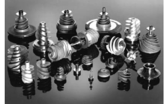
FIGURE 16 Typical pump inlet pressure stack (bar = 0.06895 psi; °C = (°F 32) 0.556; m =ft 0.3048)
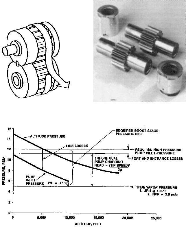
FIGURE 14 Pressure-loaded spur
gear pump
FIGURE 15 Spur gear pump gears and bearings
(Courtesy Hamilton Sundstrand)
inlet.These pressure losses include filter pressure losses (clean filter and clogged filter), oil-
to-fuel cooler pressure losses, and various coring and plumbing pressure losses. A pressure
“stack” analysis between the boost stage inlet condition and the gear stage inlet pressure
requirement must be made for all operating conditions across the pump input speed range
—
including the emergency conditions
—
to determine which operating condition is the crit-
ical sizing point for the pressure rise of the pump boost stage. A simplified example of a
pump pressure stack is presented by Figure 16. Reference 5 discusses boost impeller sizing.
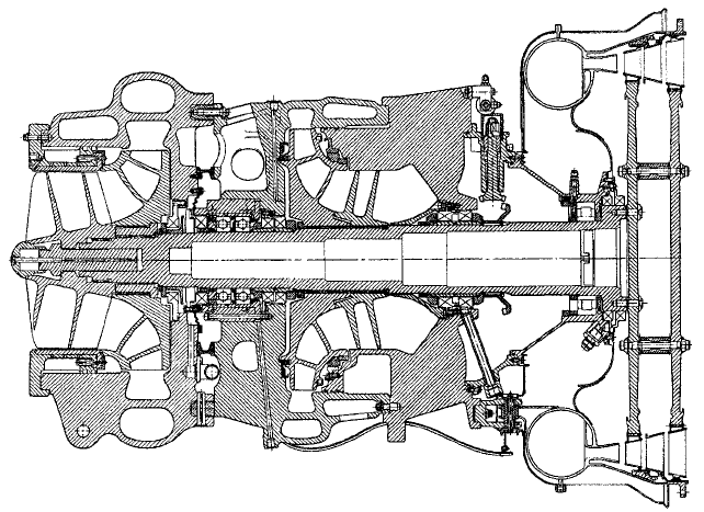
Figure 17 is a photograph of various impellers and inducers that have been used in air-
frame and engine fuel pumps. The specific speeds in units of feet of fluid, gpm, and rpm
range from 500 to 6000 (universal specific speed
s
= 0.18 to 2.2) and suction-specific speeds
in the same units range up to 40,000 (14.6).
9.19.1 AIRCRAFT FUEL PUMPS 9.427
FIGURE 17 Various impellers and inducers (Courtesy Hamilton Sundstrand)
With respect to boost stages, particular attention must be paid to minimize the con-
duction of heat from the hot high-pressure stage to the relatively cool boost stage. This is
required to avoid the possibility of vapor lock through fuel “boiling” in low-pressure regions
of the boost stage under conditions of low fuel burn flow rates and, therefore, low boost
stage through flow rates.These conditions generally occur at engine idle and descent oper-
ating conditions.
The pump-splined drive couplings are key to the reliability and safety criteria of the
pump. Similar to the pump gears, the splined couplings are fabricated from high alloy
steels with a surface hardening treatment. The design of the involute splines in terms of
profile wear must take into account the lubricant used for the splines and the misalign-
ment imposed by the various drive line elements.A spline design that will satisfy the wear
conditions at rated speed will generally meet all overload conditions, including the maxi-
mum shaft shear torque requirements. Spline lubricants that have been successfully used
include engine oil, fuel, and specially blended greases. Specific spline design parameters
must be applied for each lubricant.
PERFORMANCE CRITERIA OF ENGINE MAIN FUEL PUMPS ________________
The key performance criterion for the high-pressure positive displacement stage of a main
fuel pump is to be capable of delivering the volumetric fuel flow rate required by the
engine for all operating conditions. Before it is released for flight usage, the test sequence
with which the positive displacement stage must successfully comply is primarily directed
at evaluating the durability of the stage under the most extreme conditions it is expected
to encounter in service.There are success criteria for these tests.At the completion of each
individual test, the stage must meet its specified volumetric flow service limits. Upon com-
pletion of all the tests, the unit is subjected to a teardown inspection and the component
parts must not exhibit any unusual wear or distress and must be in a condition that is
deemed acceptable for continued service.
The key performance criterion of the boost stage is to provide adequate pressure to the
inlet of the gear stage to suppress fuel vaporization and cavitation for all operating condi-
tions; that is, with assistance from the airframe boost pumps and the emergency condi-
tions without assistance from the airframe boost pumps. The tests that confirm this

9.428 CHAPTER NINE
FIGURE 18 Gear stage performance (m
3
/h = 0.227 gpm; kW = 0.7457 hp; bar = 0.06895 psi; liter = 0.0164
in
3
; °C = (°F 32) 0.556)
capability are run in conjunction with the positive displacement stage and are subject to
similar success criteria. The performance criteria that specifically determine the design of
the boost and high-pressure main fuel pump are presented in the following discussions.
GEAR STAGE VOLUMETRIC PERFORMANCE _____________________________
The engine fuel flow requirements are specified in mass units.These must be converted to
volumetric flow units for the lowest density fuel specified for all operating conditions. For
these volumetric flow rates, the displacement required for each operating condition is
determined by applying factors for pump volumetric efficiency that encompass the tem-
perature of the fuel, production variance, and the service life flow deterioration. When the
critical displacement sizing operating condition has been established, the overall volu-
metric performance of the pump can be defined for the complete input speed and pressure
rise operating range including the required input power. Figure 18 presents the overall
performance characteristic of a pressure-loaded external spur gear high-pressure stage of
an aircraft engine main fuel pump.
GEAR STAGE CYCLIC DURABILITY _____________________________________
The ability of the pump to accept the cyclic duty imposed by modern engines without dis-
tress has been an accurate predictor of the pump’s capability of meeting its service life
requirement. The test is based upon the real-time pressure, temperature, and speed tran-
sients for engine operating conditions such as starting, ground idle, takeoff and climb,
cruise, descent, and thrust reverse.
9.19.1 AIRCRAFT FUEL PUMPS 9.429
The worst cases for the sequencing of the transients are selected to achieve the high-
est levels of stress in the gear and bearing system. The real transient times are halved and
the steady state operating times minimized to accelerate the test. The number of test
cycles and overall test time are based upon the expected service life of the pump.
LOW LUBRICITY FUEL ________________________________________________
The use of the pumped fuel as the lubricant for the pump and all components within the
fuel system is an established and required practice. Unfortunately, there is no requirement
for lubricity in the fuel specifications. Therefore, some knowledge of the minimum lubric-
ity to be expected in the field is necessary. The key factor to determine is the lubricity of
the fuel under boundary lubricating conditions for evaluating the wear characteristics of
the gear tooth profiles and the fuel lubricated spline teeth. An intensive cooperative indus-
try and government evaluation effort has identified the Exxon ball and cylinder wear test
machine as an accurate and reliable method of evaluating the lubricity characteristic of
aircraft gas turbine fuels. The pump specification will contain the fuel lubricity level with
which the pump will be required to demonstrate operation for its intended service. The
pump designer must select gear materials and geometries that are compatible with the
specified lubricity level and operating conditions.Wear experienced on low-lubricity fuel is
a threshold type of surface failure. Therefore, this threshold limit must be avoided for all
operating conditions.The test for compliance with this requirement is usually operation at
take-off and cruise conditions on the specified fluid at controlled lubricity conditions. The
fluid lubricity level is checked periodically to ensure compliance is met. See Reference 6 for
a detailed description of the test procedure.
COLD STARTS _______________________________________________________
Cold start tests demonstrate the capability of the pump to provide the performance nec-
essary to start the engine under the most severe cold conditions expected and to demon-
strate that the fits and clearances in the pump are compatible with the low temperatures.
The cold start requirement ranges from 40°F (40°C) to 65°F (53.9°C), depending
upon the fuel used and service expected.
CONTAMINATED FUEL ________________________________________________
The large amount of fuel an engine burns in operation and the widely varying service con-
ditions worldwide virtually ensures that some contaminants will be introduced into the
engine’s fuel system. In addition to these operational contaminants, there will be built-in
contaminants because of the complexity of the airframe and engine fuel system that will
be experienced in the initial operation of the pumps. Tests are specified that define oper-
ation of the pump at various operating conditions on fuel containing both liquid and solid
contaminants. These included salt water, quartz crystals, sand, and iron oxide ranging in
particle sizes from 1500 microns to less than 5 microns. These tests are more severe for
military applications than commercial applications. Military applications usually require
the contamination to be metered into the inlet of the pump in relation to the fuel flow rate
and then removed from the system downstream of the pump by a filtration system. Hence,
the contaminant is passed through the pump in a continuous single pass manner. In all
modern fuel systems, the high-pressure positive displacement stage is protected by the
engine-mounted fuel filter element. The low-pressure boost stage is not protected by the
engine-mounted filter element. Although the centrifugal boost stage is inherently capable
of operating on the specified contaminant, special design features are employed to mini-
mize the abrasive wear effects of swirling contaminated fuel.
9.430 CHAPTER NINE
V/L CAPABILITY _____________________________________________________
The reason for the need of the boost stage of an engine main fuel pump to have a V/L capa-
bility and some detail of the design requirements has been presented in previous discus-
sions.The test set-up used for V/L testing is similar to the example shown in Figure 7. The
testing is usually accomplished in two parts. Both parts are run with the maximum fuel
RVP expected in service. The first part is to evaluate the V/L performance of the pump at
all of the specified emergency conditions and prove all conditions can be met. The second
part is an endurance test at high V/L conditions to ensure that no excessive cavitation ero-
sion damage occurs that could limit the performance or life of the pump.
MINIMUM INLET PRESSURE ___________________________________________
As long as the main fuel pump is being assisted by the airframe boost pumps, it must meet
a minimum inlet pressure requirement. This inlet pressure is 5 lb/in
2
(0.345 bar) above the
true vapor pressure (TVP) of the fuel. At this condition, the main fuel pump is required to
supply the required engine fuel flow for all operating conditions.The design procedure and
details for meeting this requirement were previously discussed.
The test set-up is arranged to ensure that vapor-free fuel is provided to the inlet of the
fuel pump at 5 lb/in
2
(.345 bar) above TVP for all operating conditions. Heat exchangers
are introduced into the system as required to establish the required boost and gear stage
inlet temperatures. The full range of hot operating conditions, including the critical alti-
tude idle conditions, are run to ensure vapor lock conditions do not occur. The maximum
fuel RVP expected in service is used.
REFERENCES _______________________________________________________
1. “Aviation Fuel Properties.” Coordinating Research Council, Society of Automotive
Engineers SAE.
2. “Aircraft Fuel System Vapor-Liquid Ratio Parameter.” Aerospace Information Report
AIR1326, Society of Automotive Engineers SAE.
3. Baker, O. “Simultaneous Flow of Oil and Gas.” The Oil and Gas Journal, July, 1954.
4. Greenberg, C. “Flight Testing with Hot JP-4 Fuel.” American Helicopter Society.
Preprint No. RWP-11, 1982.
5. Rohatgi, V. “Sizing of an Aircraft Fuel Pump.” Transactions of the ASME, Vol. 117,
June 1995.
6. “Aircraft and Aircraft Engine Fuel Pump Low Lubricity Fluid Endurance Test.” Aero-
space Recommended Practice ARP 1797, Society of Automotive Engineers SAE.
9.19.2
LIQUID ROCKET PROPELLANT
PUMPS
PAUL COOPER
RAYMOND B. FURST
ADIEL GUINZBURG
9.431
Liquid-fueled rocket engines have been used on all the major launch vehicles, including
the large, first-stage booster rockets as well as the upper stages of those same vehicles, and
various smaller vehicles such as the lunar lander. The propellant pumps are major com-
ponents of the engine. They pump a) the oxidizer, usually liquid oxygen, and b) the fuel,
which is usually liquid hydrogen, up to the high pressures needed to feed the combustion
processes. In the past, a widely used fuel was kerosene in a rocket propellant formulation
specified as “RP1.”
Of necessity, the pumps for these engines must have the minimum possible size and
weight. They therefore run at extremely high speeds. Most have inducers or are fed by
inducer pumps. These inducers have extremely high suction-specific-speed capability,
N
ss
exceeding 35,400 (
ss
13) and being as high as 70,000 (
ss
26) in liquid hydro-
gen
1
. This is so because the hydrogen is nearer its thermodynamic critical point and so
generates less vapor volume when it cavitates than do other propellants. (See the dis-
cussion under “NPSH-Effects” in Section 2.1. All symbols in this subsection are defined
in the nomenclature of that Section 2.1.) The main engine propellant pumps have
higher heads per stage than any other centrifugal pumps in existence.As such, they are
the world’s highest-energy pumps, as indicated in Figure 32 and Table 13 of Section 2.1.
Whereas the high-energy pump portion of that section is devoted largely to the chal-
lenges of designing such machines for long life
—
say 40,000 hours or more
—
the life of a
rocket engine pump is measured in minutes; or, in the case of reusable rockets, not much
more than a few hours. For good materials choices, such a short operating life means
that these pumps are unlikely to suffer failure from cavitation erosion or other wear-
related phenomena, despite the high inlet tip speeds of the inducers and impellers.
Extreme attention to details of the mechanical design is required in order for these
pumps to survive at design conditions
—
near which they generally operate.A few exam-
ples of rocket propellant pumps are given in this subsection, but many others also exist
in various configurations
1,2
.
9.432 CHAPTER NINE
FIGURE 1 F-1 Turbopump assembly, used on Saturn V first stage rocket engine (Courtesy of The Boeing Company)
THE SATURN V BOOSTER ROCKET ENGINES ____________________________
The Saturn V booster rocket was used in the Apollo program of the 1960s and ’70s, which
landed men on the moon. This rocket had a vertical height of more than 350 ft (197 m) at
launch. The first or lowest stage was the largest and was propelled by five F-1 engines,
each producing 1.5 million pounds (6.7 million N) of thrust. Propellants were liquid oxy-
gen and RP1. Each engine was topped by a turbopump assembly that included both pumps
on the same shaft and driven by the same hot-gas turbine. A cross-section of this assem-
bly is shown in Figure 1, the two pumps being arranged in a back-to-back configuration
and each having an inducer. The RP1 pump is the one next to the turbine, there being a
considerably lower temperature difference between RP1 and the hot gas flowing through
the turbine from the combustor than there would be for liquid oxygen. At the design speed
of 5,490 rpm, the two pumps together consumed 52,700 hp (39 MW)
—
and considerably
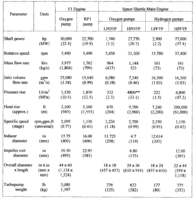
more at overspeed (approximately 6000 rpm). Table 13 of Section 2.1 contains performance
figures. Essentially the same data are presented in the following descriptions of the
pumps, which are summarized in Table 1. The table has been developed from various
sources, including the references cited at the end of this section, as well as information
supplied by the Boeing Company.
• The oxygen pump took in the liquid axially through a 15.75-in (400-mm) diameter
inducer at the opposite end of the assembly from the turbine, as seen in Figure 1.
Designed for a suction-specific speed N
ss
of 35,400 (
ss
13) meant that when ingesting
25,080 gpm (1.58 m
3
/s) this machine could operate at an inlet static pressure of 22 lb/in
2
(0.15 MPa) above the vapor pressure p
v
of the liquid oxygen. Because this liquid is
cryogenic, p
v
equals the pressure inside the fuel tank of the first stage of the rocket,
which was not much above atmospheric pressure. Actually, the g-force and head of liquid
in the tankage above the pump combined to provide additional available NPSH. This
pump, which was designed for a specific speed N
s
of about 2,100 (
s
0.77), consumed
9.19.2 LIQUID ROCKET PROPELLANT PUMPS 9.433
TABLE 1 Data on liquid rocket propellant pumps*
*Compiled from information supplied by The Boeing Company and References 1–5.
**Main stage. Small preburner stage pumps 117 lb/sec (53 kg/s) to approximately 3300 psi (23
MPa) above main stage discharge.
30,000 hp (22 MW) or 57 percent of the total turbine shaft power, and it generated over
1,500 lb/in
2
(10 MPa) of pressure rise.
• The fuel (RP1) pump, being in the middle of the turbopump assembly, had to take in the
15,640 gpm (0.99 m
3
/s) of RP1 through a side inlet piping configuration, which generally
results in less N
ss
-capability than axial inlet piping. Here the inducer is larger and the
flow rate lower than for the liquid oxygen pump, creating the potential for higher N
ss
; yet
it ended up being lower, namely N
ss
34,200 (
ss
12.5). Nonetheless, this enabled the
RP1 pump to operate at a static inlet pressure as low as 16 lb/in
2
(0.11 MPa) above the
(negligible) vapor pressure of this liquid. With specific speed N
s
just over 1,100 (0.40),
this pump consumed the remaining turbine shaft power of 22,700 hp (17 MW) and gen-
erated a pressure rise of just over 1,800 lb/in
2
(12.4 MPa).
• Throughout the burn, these pumps deviated no more than about 8 percent from the design
value of Q/N; that is, the flow coefficient was essentially constant. Thus, this turbopump
9.434 CHAPTER NINE
did not suffer from the off-design low-flow conditions of most commercial, industrial
pumps, as described in Section 2.1 and Subsection 2.3.2, including those of high energy
level, which made it a little easier for this machine to operate at high energy levels.
THE SPACE SHUTTLE MAIN ENGINES___________________________________
The space shuttle program, which began in the 1970s, dealt with a launch vehicle that was
flanked by two large solid-fueled rockets. In the middle at the base were three liquid-
fueled “main” engines, each having nearly 500,000 lb (2.2 million N) thrust and propelled
by hydrogen fuel and oxygen at a mixture mass ratio of 6:1 (oxygen to hydrogen). Each of
these space shuttle main engines (SSME’s) has a dedicated pumping system, consisting of
a low-pressure single-stage inducer-type pump for each propellant, which in turn feeds a
high pressure pump. Three of these four pumps can be seen in the photograph of the
engine in Figure 2. Located up above is the low-pressure hydrogen pump, with its large
discharge line going off to the right and down to the high-pressure hydrogen pump below.
Opposite, on the left, is the high-pressure oxygen pump, with its large inlet line also in
view. Engineering of these high-pressure propellant pumps embodied a triple challenge in
comparison to the F-1 pumps, because a) this engine was designed to be re-used, so the
pumps had to have a life of 7.5 hours with 100 starts; b) the pumps for this engine have
higher energy levels than the F-1 pumps, and, c) due to the mission profile, they have to
be throttled back further from the design point. Each of these pumps is boosted by a low-
pressure inducer-type pump to suppress cavitation enough to maintain performance
3
.
The propellant flow system is illustrated in the schematic diagram of Figure 3. (The
pump speeds, pressures, and flow rates shown in this figure are somewhat lower than the
design conditions of Table 1, which for the SSME pertains to the maximum engine thrust
level.) All four of the pumps are driven by turbines and so are called “turbopumps.” The
system picks itself up by its own bootstraps, so to speak; each low-pressure turbopump
boosts the flow to the corresponding high-pressure pump and is driven by the same fluid
that it pumps. This driving fluid comes back from each high-pressure pump, the low-
pressure oxygen turbopump (LPOTP) being driven by recirculated liquid oxygen, and the
low-pressure hydrogen or fuel turbopump (LPFTP) turbine being fed by gaseous hydrogen
heated by the thrust chamber, as indicated in Figure 3.
The high-pressure pumps are driven by turbines fed by “preburners,” which are com-
bustors that burn hydrogen-rich. Some of the fuel entering these combustors is the
gaseous hydrogen coming from the LPFTP turbine exhaust, which cools the turbine hous-
ings on the way to the preburners. But most of the fuel supplied to the preburners is the
80 percent of the liquid hydrogen discharging from the high-pressure fuel turbopump
(HPFTP), which first flows through the cooling passages of the nozzle walls. [Eleven per-
cent of the oxygen is also fed to the preburners by way of the preburner boost stage that
is a part of the high-pressure oxygen turbopump (HPOTP) package. Finally, the partially
burned fuel passes as a hot gas into the main combustion chamber, where more oxygen is
added and the pressure is 3,000 lb/in
2
absolute (21 MPa)
3,4
.] Most of the remaining 20 per-
cent of the hydrogen is that which was already described as cooling the main combustion
chamber and, along the way, becomes gaseous and powers the drive turbine of the LPFTP.
It also cools the hot-gas manifold and injector and pressurizes (in a small amount) the fuel
tank. Approximately 75 percent of the liquid from the high-pressure oxygen turbopump
(HPOTP) goes directly to the main combustion chamber, 11 percent to the preburners (as
already stated), about 13 percent to drive the turbine of the low-pressure oxygen turbop-
ump (LPOTP), and a small amount is sent to pressurize the tank.
5
A brief description of
each pump follows:
• The low-pressure oxygen turbopump (LPOTP) consumes 1,740 hp (1.30 MW) and runs
at 5,450 rpm. It has a single-stage, axial-flow, inducer-type impeller that is 11.725 in
(298 mm) in diameter and is driven by a six-stage liquid-oxygen hydraulic turbine.
Pump head rise is 670 ft (204 m) so the HPOTP therefore operates without pressure
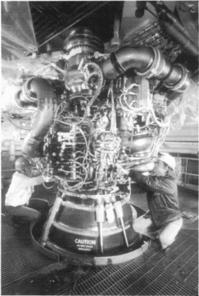
FIGURE 2 The space shuttle main engine (SSME) (National Geographic Magazine, March 1981: Jon
Schneeberger/NGS Image Collection)
9.19.2 LIQUID ROCKET PROPELLANT PUMPS
9.435