Pump Handbook by Igor J. Karassik, Joseph P. Messina, Paul Cooper, Charles C. Heald - 3rd edition
Подождите немного. Документ загружается.


9.17 OIL WELLS 9.395
TABLE 6 Typical characteristics electric submersible centrifugal pumps
Well Motor Pump
Pump capacity,
Pump
casing OD, OD,
Motor power, bbl/day
head per Efficiency,
OD, in in in
hp (kW) (m
3
/day)
stage, pump
(mm) (mm) (mm) Min Max Min Max ft (m) only, %
4.500 3.75 3.75 25 127 400 1,500 16 54
(114) (95) (95) (18.7) (94.7) (64) (238) (5.2)
5.500 4.56 4.56 120 240 400 2,800 23 61
(140) (116) (116) (89.5) (179) (64) (445) (7.5)
7.000 4.56 5.40 120
—
1,400 7,000 30 68
(178) (116) (137) (89.5)
—
(223) (1113) (9.8)
—
5.40 5.40
—
600 1,400 7,000
——
—
(137) (137)
—
(488) (223) (1113)
—
8.625 4.56 6.50 120
—
12,000 20,000 42 72
(219) (116) (165) (89.5)
—
(1908) (3180) (13.8)
—
5.40 6.50
—
600 12,000 20,000
——
—
(137) (165)
—
(488) (1908) (3180)
—
—
7.38 6.50
—
720 12,000 20,000
——
—
(188) (165) (537) (1908) (3180)
—
The small diameter of the casing in which these pumps must be run severely limits
design options. Length must be substituted for diameter to achieve the needed character-
istics, and the motor design of the electric submersible pump barely resembles its surface
counterpart. Single-motor assemblies range up to 32 ft (9.8 m) in length, and when power
requirements exceed that of a single motor, two or more motors are assembled in tandem.
The pumps must use many stages in order to gain the required head. The smallest-
diameter pump
—
3.75-in (95.2-mm) OD
—
has 166 stages in an overall length of 12 ft (3.7
m). In deeper wells, two or more of these units can be assembled in tandem to gain the
needed head. Manufacturers catalog pump combinations with as many as 400 stages.
Table 6 gives typical data on the more common sizes.The numbers in the table are not lim-
its, and manufacturers have available both smaller and larger sizes than those shown.
HYDRAULIC SUBMERSIBLE CENTRIFUGAL PUMPS _______________________
Hydraulic turbine drive submersible pumps have been an emerging technology since the
1980s. They are particularly suited for use in wells where other artificial lift technologies
are unsuitable due to high liquid viscosity, high temperature, or high gas-to-oil ratio. The
hydraulic turbine drive submersible pumpset unit comprises a multistage turbine
mounted on a common shaft with a multistage centrifugal pump located directly below it.
They are installed in the well bore as part of the production tubing, by wireline or coiled
tubing methods, and are submerged in the well fluid.
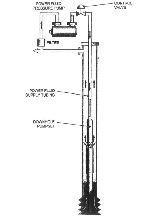
The simplest hydraulic submersible pump system consists of a surface charge pump,
power fluid control valve, hydraulic submersible pumpset, and a power fluid filter (Figure
16). In operation, power fluid is boosted in pressure by the surface charge pump and is
passed through the control valve before being injected down the well tubing and into the
turbine. The power fluid drives the turbine stages, causing the pump to rotate before
exhausting at the lower end of the turbine unit. The pump suction flow enters at the bot-
tom of the pump and is boosted in pressure through the various pump stages before dis-
charging at the upper end of the pump unit. The most common configuration (open loop)
results in the discharged pump flow comingling with the exhaust power fluid and return-
ing to the surface for separation and processing. The power fluid is then filtered and
9.396 CHAPTER NINE
FIGURE 16 Aquifier lift principle of operation (Weir Pumps Ltd.)
returned to the surface charge pump to begin the cycle over again.The turbine power fluid
can be produced water, aquifer water, or produced oil, depending on which is more suitable
for the application under consideration. The ratio of power to produced fluid is in the
region of 1:1, although this can be varied to suit specific operational flow and pressure
requirements.
Oil field artificial lift systems require a high degree of flexibility to take account of
changing well conditions that may alter over the installed life of the pumpset. The
hydraulic submersible pump is a nominally constant power machine that will use all the

9.17 OIL WELLS 9.397
TABLE 7 Typical characteristics of a hydraulic submersible centrifugal pump
Max. Pump Pump
Well Turbine Pump Capacity Head per Efficiency,
casing OD, OD, OD, bbl/day stage, pump
in (mm) in (mm) in (mm) (m
3
/day) ft (m) only, %
5.500 (140) 3.465 (88) 4.528 (115) ,8000 (1260) 143 (44) 62
7.000 (178) 5.433 (138) 5.709 (145) 11,000 (1740) 165 (50) 68.5
7.765 (197) 5.433 (138) 5.906 (150) 19,000 (3000) 165 (50) 70
9.625 (244) 6.772 (172) 7.480 (190) 25,000 (3950) 158 (48) 76
10.750 (273) 8.858 (225) 8.662 (220) 39,000 (6160) 158 (48) 78
11.750 (298) 8.858 (225) 10.630 (270) 75,000 (11,900) 193 (59) 79.5
power being fed to it in the form of flow and pressure energy. By this fact, the pump will
automatically vary its speed to take into account varying well conditions. Typical pump
speeds are in the region of 8500 rpm for smaller unit to 4000 rpm for larger units. Designs
are available from 3000 barrels/day to 75,000 barrels/day (480 m
3
/day to 12,000 m
3
/day),
depending on the pumpset configuration. Typical characteristics of hydraulic submersible
centrifugal pumps are listed in Table 7.
The hydraulic submersible pump uses clean turbine power fluid to continually flush
the pump end bearings while in operation. Hydrostatic bearings are used and the absence
of any rolling element bearings or mechanical seals provides a simple, robust construction.
The high power density of the hydraulic turbine and the relatively high speed of the pump
makes for a compact unit typically less than 20 ft (6 m) long.
OFFSHORE OIL WELL PUMPS _________________________________________
Most offshore oil well platforms are located in high-pressure fields where the wells will
flow from natural pressure for several years.When the pressure declines, the wells are fre-
quently produced with gas lift, where high-pressure gas is directed down the casing. This
gas mixes with the well fluid at the bottom of the tubing, and the fluid-gas mixture light-
ens the fluid gradient in the tubing string to a point where the bottom hole pressure is suf-
ficient to cause the well to flow. Where gas lift is not applicable, wells are pumped with
subsurface submersible electric pumps, subsurface hydraulic reciprocating or jet pumps,
or sucker rod pumping systems. A few wells are completed with the well head on the ocean
floor. These must either flow or be gas-lifted, and the other systems are not applicable.
FURTHER READING __________________________________________________
Brennan, J. R. Engineering Data and Production Calculations. National Supply, Los
Nietos, CA, 1968.
Brown, K. The Technology of Artificial Lift Methods, Vol. 2b. PennWell Publishing, Tulsa,
OK, 1980.
Primer of Oil and Gas Production. 3rd ed., Johnson Printing, Dallas, TX, 1976.
Shanahan, S. T. The Basics of Subsurface Oil Well Pumps, BMW-Monarch, Gardena, CA,
1975.
Wilson, P. M. Introduction to Hydraulic Pumping, Kobe, Huntington Park, CA, 1976.

The regime of cryogenic technology has been generally taken to indicate temperatures
colder than 100°F (73°C). Fluids such as liquid oxygen, nitrogen, hydrogen, helium,
argon, methane, and ethane, with normal boiling points below 100°F (73°C) are called
cryogenic fluids.
For the pump designer, the cryogenic regime requires consideration of the effect of low
temperatures on the properties of construction materials and the effect of varying shrink-
age rates on critical fits and clearances. The problem is further complicated by the fact
that cryogenic fluids are stored at near atmospheric pressure and must be pumped at or
near their normal boiling point, so the only NPSH available is that due to the liquid level
above the pump suction.
The history of commercial cryogenic pumping divides into two eras. The first, com-
mencing in the early 1930s with the first liquid oxygen plant in the United States, was the
period in which end-suction shaft seal pumps were developed and produced for pumping
liquefied atmospheric gases, such as liquid oxygen, nitrogen, and argon.This industry grew
until the late 1960s.Though continuing to grow, the explosive period appears to have ended.
The second era commenced in 1959 with the first transport of a commercial cargo of liq-
uefied natural gas (LNG) from Lake Charles, La., across the Atlantic Ocean to England.
This voyage, carrying an almost token quantity of 5000 m
3
of LNG, inaugurated an era of
international trade in liquefied hydrocarbon gases that has grown with astounding rapid-
ity and seems still to be barely on the threshold of realizing its full potential.
ATMOSPHERIC GASES _______________________________________________
Cryogenic pumps first came into being with the production of liquefied atmospheric gases
in commercial quantities. The initial liquefaction of air and the subsequent separation of
SECTION 9.18
CRYOGENIC LIQUEFIED
GAS SERVICE
L. R. SMITH
THOMAS MOYES
9.399
9.400 CHAPTER NINE
FIGURE 1A In-flight refueling pump (J. C. Carter Company, Inc.)
oxygen and nitrogen did not require pumps because the small volume of liquids produced
could be readily transferred by pressure. Early pumps, where needed, were designed and
built by the gas companies themselves and were primarily used to fill high-pressure bot-
tles or cylinders. Flows were very low, so positive displacement pumps were commonly
used. These were notoriously inefficient, primarily because of the flashing that occurred
during the intake stroke and led to a very low volumetric efficiency. However, the low vol-
ume of product being handled permitted this efficiency to be tolerated.
The World War II development of rocket engines that used liquid oxygen as an oxidizer
to burn kerosene fuel and the postwar development of the large rocket booster required
the development of centrifugal pumps to feed the propellants to the engine.These turbine-
driven rocket engine pumps were adapted to electric motors for use in transferring the
propellants from storage into the rocket’s tanks because there were no high-capacity cryo-
genic pumps available from the industry. Although these early rocket pumps were also
inefficient, they could be tolerated in the rocket because the fluid was burned immediately
and temperature rise across the pump was not a problem.
Two other developments in the early postwar years increased the volume of liquefied
gases in industrial applications.The first was the development of the basic oxygen furnace
for making steel, and the second was the use of liquefied nitrogen in the fast-freezing of
foods and as an inert atmosphere for heat-treating and chemical processes. These devel-
opments required the storage and transfer of large volumes of liquids, so the boiloff loss
due to pump inefficiency became a major economic factor in the profit and loss of the liq-
9.18 CRYOGENIC LIQUEFIED GAS SERVICE 9.401
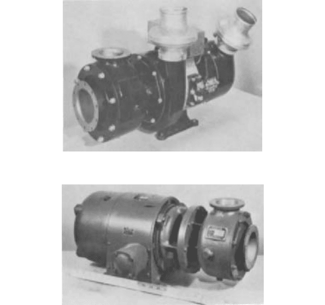
FIGURE 1B DC-motor-driven refueling pump with original flanges (J. C. Carter Company, Inc.)
uefaction company. The major companies instituted internal studies to reduce these losses,
and soon the transfer pumps were brought under scrutiny.
Thus a two-pronged impetus developed to find pumps that would more efficiently and
reliably transfer these valuable liquids; the first was the need to load military rockets with
the coldest possible liquid with utmost reliability, and the second was from industry. Inves-
tigators studying the problem first turned to the producers of commercial pumps. How-
ever, because the pump volumes required were small and the technical problems
formidable, they were unable to retain the interest of the major manufacturers and so
turned to small producers of custom-designed pumps.
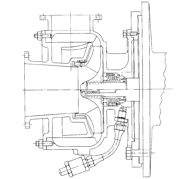
The earliest custom producer to enter the field was a builder of high-capacity in-flight
refueling pumps for the military. One of these pumps was adapted to a commercial 60-Hz
electric motor using a newly designed face-type shaft seal with the stationary face
mounted on a stainless steel convoluted bellows. A cross section of this pump is shown in
Figure la.
The refueling pump was constructed of aluminum castings with bronze wear rings and
stainless steel trim. These materials were good choices for cryogenic service as well, and
so, aside from the seal, it was necessary only to change to standard pipe flanges on the
inlet and discharge nozzles. Figure lb shows this pump mounted on the original dc aircraft
motor used on the KB29 airplane, transferred to a 60-Hz, 3-phase motor but still with the
original flanges. Figure 1c shows the full commercial cryogenic configuration with ANSI
FIGURE 1C Full commercial cryogenics configuration of dc-motor-driven refueling pump with ANSI flanges
(J. C. Carter Company, Inc.)
9.402 CHAPTER NINE
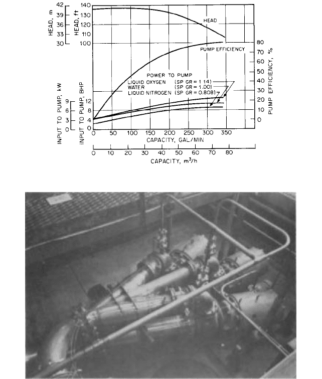
FIGURE 2 Performance characteristics for a refueling pump at 3500 rpm (J. C. Company, Inc.)
FIGURE 3 Cryogenic pumps for loading liquid-propelled ICBMs (J. C. Company, Inc.)
standard flanges and stainless steel thermal barrier/distance piece for mounting the pump
onto the motor. The pump, originally designed under the space and weight limitations of
aircraft service, also fit the requirements of cryogenic pumping in that the low heat capac-
ity and surface area resulted in short cool-down time and low heat leak. Because the pump
was also very efficient (Figure 2), the boiloff problem was greatly alleviated.The gas indus-
try welcomed this pump, and it became one of the most popular transfer pumps for load-
ing and unloading tank cars and trailers.
Following the lead set by this pump, several other small manufacturers began build-
ing similar pumps. As the industry grew, pumps of larger capacity and higher heads
were built, covering the range from 4 gpm (0.9 m
3
/h), used in transferring liquid from
rectifier columns to storage, to more than 5000 gpm (1125 m
3
/h), used for loading the
early liquid-propelled ICBMs during the 1960s (Figure 3). Only one of these latter sys-
tems was built. The pumps shown in Figure 3 were about the largest end-suction close-
9.18 CRYOGENIC LIQUEFIED GAS SERVICE 9.403
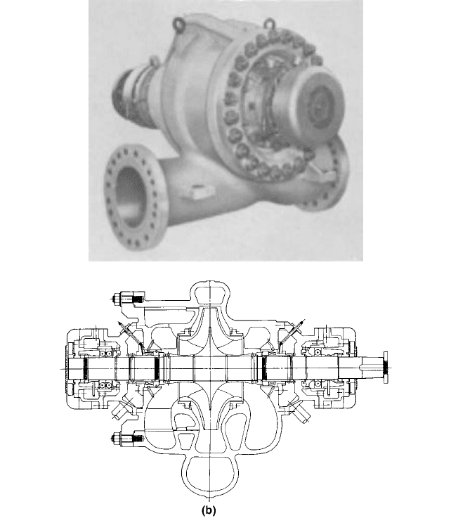
FIGURE 4 (a) Double-suction cryogenic pump, (b) cross-sectional view (Flowserve Corporation)
coupled pumps ever built. The pump built to load the Saturn rocket at 10,000 gpm (2250
m
3
/h) was not close-coupled and was possibly the only double-suction cryogenic pump
ever built (Figure 4).
LIQUEFIED HYDROCARBON GASES ____________________________________
The cryogenic fluids encountered in this service are primarily LNG (a mixture that is nor-
mally more than 90% methane), ethylene, and ethane, along with the liquefied petroleum
gases (LPG) propane and butane. A novel approach to pumping these fluids was intro-
duced in 1959 with the application of the submerged electric-motor-driven pump. Because
these fluids are excellent dielectrics, part of the pumped fluid stream can be directed
9.404 CHAPTER NINE
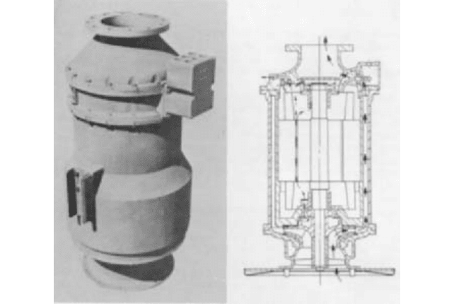
FIGURE 5 On-board cryogenic cargo pumps—photograph on left and cross-section on right showing flow through
the motor (J.C. Carter Company, Inc.)
through the motor to cool it and lubricate the bearings.There is no need to can or treat the
windings with anything other than specially selected varnishes. Many advantages accrue
to this design, such as
• No cool-down requirement on pumps installed in tanks
• High inherent reliability due to protection from corrosion and humidity and elimination
of shaft seal
• Low hazard due to 100% rich environment
• Minimal differential shrinkage problems
• Capability of directing rejected heat in accordance with designer’s wishes
Also, the pump is close-coupled to the motor, eliminating the need for a long line shaft,
line shaft bearing problems, and differential shrinkage problems. As a result, higher
speeds can be used and pumps can be smaller and less expensive.
This construction has found many applications that have led to a variety of configura-
tions, including the single and multistage units used in the liquefaction process plant to
transfer to storage, load and unload cargo ships, and pump to high pressures for regasifi-
cation. The pumps can be mounted in tubes inside the tanks so they can be removed for
service through the roof without emptying the tank, thus eliminating the need for an
opening in the bottom of the tank. They are also mounted in suction barrels that can be
maintained cold indefinitely on instant standby.
A typical cargo pump for use on board ships is shown in Figure 5. This pump uses alu-
minum castings for all housings as well as for the pump impeller. The motor uses electri-
cal iron laminations, a stainless steel shaft, and stainless steel ball bearings with special
nonmetallic separators.The path of the top wear ring flow up through the motor and back
into the tank is easily seen.
This pump stands about 5 ft (1.5 m) high from the suction flange to the discharge
flange. Flow is typically in the 5000-gpm (1125-m
3
/h) range. Motors with ratings up to 450
hp (336 kW) are available.
9.18 CRYOGENIC LIQUEFIED GAS SERVICE 9.405
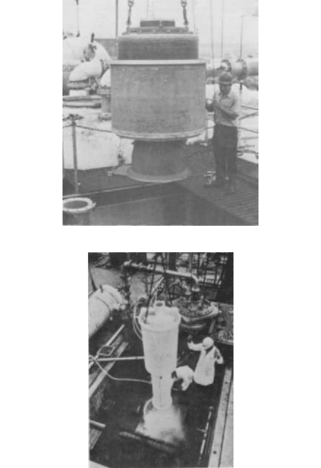
FIGURE 6 Ship-loading cryogenic pump (J.C. Carter Company, Inc.)
FIGURE 7 Multistage cryogenic pump on test stand (J.C. Carter Company, Inc.)
Other configurations are shown is Figures 6 and 7. Figure 6 is a typical ship-loading
pump provided with an 800-hp (597 kW) motor and capable of pumping more than 20,000
gpm (4500 m
3
/h). This type of pump is designed for mounting in a suction pot. Figure 7