Pump Handbook by Igor J. Karassik, Joseph P. Messina, Paul Cooper, Charles C. Heald - 3rd edition
Подождите немного. Документ загружается.


STEAM POWER PLANT CYCLES________________________________________
Power is produced in a steam power plant by supplying heat energy to the feedwater,
changing it into steam under pressure, and then transforming part of this energy into
mechanical energy in a heat engine to do useful work.The feedwater therefore acts merely
as a conveyor of energy. The basic elements of a steam power plant are the heat engine, the
boiler, and a means of getting water in the boiler. Modern power plants use steam turbines
as heat engines; except for very small plants, centrifugal boiler-feed pumps are used.
This basic cycle is improved by connecting a condenser to the steam turbine exhaust
and by heating the feedwater with steam extracted from an intermediate stage of the
main turbine. This results in an improvement of the cycle efficiency, provides deaeration
of the feedwater, and eliminates the introduction of cold water into the boiler and the
resulting temperature strains on the latter. The combination of the condensing and feed-
water heating cycle (Figure 1) requires a minimum of three pumps: the condensate pump,
which transfers the condensate from the condenser hot well into the direct-contact heater;
the boiler-feed pump; and a circulating pump, which forces cold water through the con-
denser tubes to condense the exhaust steam. This cycle is very common and is used in
most small steam power plants.A number of auxiliary services not illustrated in Figure 1
are normally used, such as service water pumps, cooling pumps, ash-sluicing pumps, oil-
circulating pumps, and the like.
The required improvements in operating economy in the 1970s dictated further refine-
ments in the steam cycle, and these created new demands for power plant centrifugal
pumping equipment. This evolution involved a steady increase in operating pressures
until 2400 lb/in
2
(165 bar*) steam turbines became quite common. Many plants are oper-
ating at supercritical steam pressures of 3500 lb/in
2
(240 bar). Several central station
IGOR J. KARASSIK
RICHARD P. KOCH
9.73
SECTION 9.5
STEAM POWER PLANTS
*1 bar 10
5
Pa.

9.74 CHAPTER NINE
FIGURE 1 Simple steam power cycle
FIGURE 2 Natural gas and steam, combined cycle power
plants constructed in the late 1970s are operating between 4000 and 5000 lb/in
2
(275 and
345 bar).
Other refinements were directed toward a greater utilization of heat through increased
feed-water heating, introducing a need for heater drain pumps-equipment with definite
problems of its own. Finally, the introduction of forced or controlled circulation as opposed
to natural circulation at 650°F (343°C) in boilers created a demand for pumping equip-
ment of again an entirely special character.
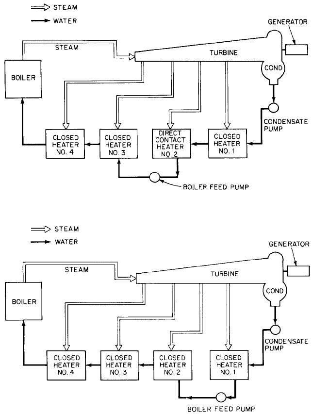
Although direct-contact heaters would have thermodynamic advantages, a separate
pump would be required after each such heater. The use of a group of closed heaters per-
mits a single boiler feed pump to discharge through these heaters and into the boiler. The
average power plant is based on a compromise system: one direct-contact heater is used
for feedwater deaeration, whereas several additional heaters of the closed type are located
9.5 STEAM POWER PLANTS 9.75
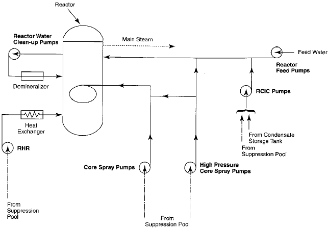
FIGURE 3 Nuclear power steam cycle, boiling water reactor
upstream as well as downstream of the direct-contact heater and of the boiler-feed pump
(Figure 5). Such a cycle is termed an open cycle. The major variation is the closed cycle,
where the deaeration is accomplished in the condenser hot well and all heaters are of the
closed type (Figure 6).
Electric power generation technology advanced into the 1970s when the conventional
coal and gas fired boilers were replaced with nuclear fission reactors. Nuclear power gen-
eration utilizes two concepts for generating steam: boiling water reactors (Figure 3) where
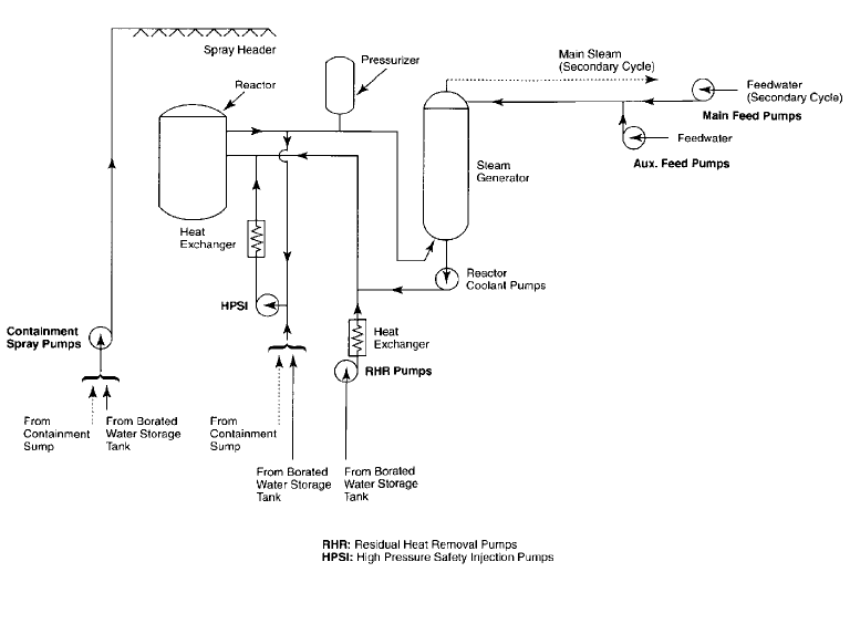
the feedwater travels directly to the reactor, and pressurized water reactors (Figure 4)
where the feedwater travels through a steam generator.
In the 1980s, the evolution of power generation industry continued with the construc-
tion of combined-cycle units. This technology increased the efficiency and improved the
heat rate by utilizing the exhaust gases of primary gas turbines to produce valuable steam
to drive steam-powered generators (Figure 2). Gas turbine-fired plant construction
expanded as emphasis increased on environental issues related to coal- and oil-fired plants.
STEAM POWER PLANT PUMPING SERVICES _____________________________
Pumps are very important components of a steam electric power plant. The major appli-
cations are the condensate, boiler-feed, heater drain, and condenser circulating pumps.
The all-inclusive category of “miscellaneous pumps” includes such a variety of services
that it merits being broken down into its components and included in a representative list-
ing. Table 1 provides such a listing for conventional (fossil fuel) steam power plants. The
list is not necessarily complete but is reasonably representative.
BOILER-FEED PUMPS ________________________________________________
Under the term conditions of service are included not only the pump capacity, discharge
pressure, suction conditions, and feedwater temperature but also the chemical analysis of
RCIC: Reactor Core Isolation Cooling Pumps
RHR: Residual Heat Removal Pumps
9.76
FIGURE 4 Nuclear power steam cycle, pressurized water reactor
9.5 STEAM POWER PLANTS 9.77
FIGURE 5 Open feedwater cycle with one deaerator and several closed heaters
FIGURE 6 Closed feedwater cycle
the feedwater, the pH at pumping temperature, and other pertinent data that may reflect
upon the hydraulic and mechanical design of the boiler-feed pumps. Preferably, a complete
layout of the feedwater system and of the heat balance diagram should be supplied to the
boiler-feed pump manufacturer. The study of this layout will often permit the manufac-
turer to suggest an alternate arrangement of the equipment that would result in a more
economical operation, in a lower installation cost, or even in longer equipment life to
reduce the eventual maintenance expense.

9.78 CHAPTER NINE
TABLE 1 Pump services in conventional steam power plants
Fuel oil system (continued)
Low-temperature oil-circulating pumps
Distillate oil unloading pumps
Fuel oil additive unloading pumps
Fuel oil additive transfer pumps
Fuel oil additive metering pumps
Fuel oil hose drain pumps
Lubricating oil system
Lubricating transfer pumps
Starting oil pumps
Main oil pumps
Emergency oil pumps
Centrifuge feed pumps
Fire protection system
Fire pumps
Jockey pumps
Foam proportioning pumps
Heating, ventilating, and air conditioning system
Hot water circulating pumps
Chilled water pumps
Service water system
Service water pumps
Air preheater wash pumps
Cooling water booster pumps
Primary air heating coil condensate return
pumps
Heating drain tank return pumps
Sump pumps
Closed cooling water system pumps
Miscellaneous
Ash sluice pumps
Slurry pumps
Acid cleaning pumps
Hydrostatic pressure test pumps
Turbogenerator and auxiliaries
Condenser circulating pumps
Screen wash-water pumps
Cooling tower make-up pumps
Steam generator equipment
Condensate pumps
Condensate booster pumps
Boiler-feed pumps
Boiler-feed booster pumps
Deaerator make-up pumps
Heater drain pumps (low and high pressure)
Chemical feed system
Amine pumps
Hydrazine pumps
Phosphate pumps
Caustic feed pumps
Acid feed pumps
Ammonia pumps
Regeneration waste pumps
Demineralizer pumps
Neutralizing metering pumps
Neutralizing tank sump pumps
Acid bulk-transfer pumps
Caustic bulk-transfer pumps
Inlet and effluent demineralizer waste tank
pumps
Fuel oil system
Fuel oil transfer pumps
Secondary fuel oil pumps
Secondary fuel oil heater drip pumps
Ignitor oil pumps
Auxiliary boiler fuel pumps
Warm-up oil pumps
High-temperature oil-circulating pumps
Boiler-Feed Pump Capacity The total boiler-feed pump capacity is established by
adding to the maximum boiler flow a margin to cover boiler swings and the eventual
reduction in effective capacity from wear. This margin varies from as much as 20% in
small plants to as little as 5% in the larger central stations. The total required capacity
must be either handled by a single pump or subdivided between several duplicate pumps
operating in parallel. Industrial power plants generally use several pumps. Central sta-
tions tend to use single full-capacity pumps to serve turbogenerators up to a rating of 100
or even 200 MW and two pumps in parallel for larger installations. There are obviously
exceptions to this practice: some engineers prefer the use of multiple pumps even for small
installations, whereas single steam-turbine-driven boiler-feed pumps designed for full
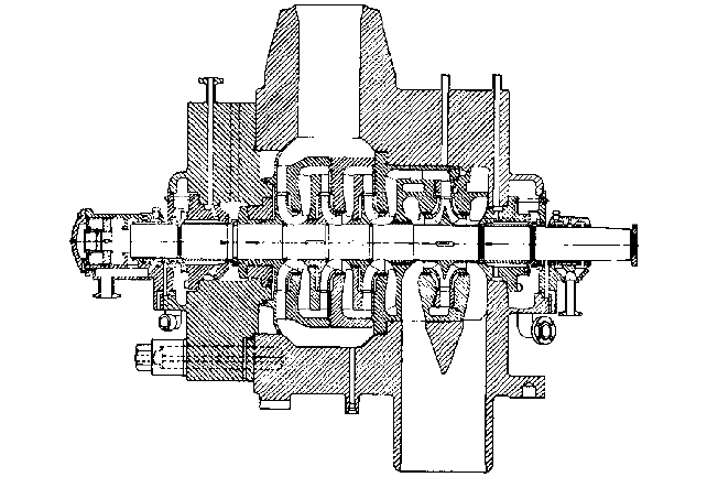
capacity are installed for units as large as 1300 MW (Figure 7). A spare boiler-feed pump
is generally included in industrial plants. The trend in combined cycle cogeneration plants
is to install two 100% capacity pumps. This provides optimum reliability and availability.
Combined cycle plants are equipped with multiple feedwater pump arrangements related
to the gas turbine exhaust stage pressure. Installation variations include high pressure
intermediate pressure (often a stage take-off from the high pressure pump) and the low
pressure feedwater pumps.
Suction Conditions The net positive suction head (NPSH) represents the net suction
head at the pump suction, referred to the pump centerline, over and above the vapor pres-
sure of the feedwater. If the pump takes its suction from a deaerating heater, as in Fig-
ure 5, the feedwater in the storage space is under a pressure equivalent to the vapor
pressure corresponding to its temperature.Therefore the NPSH is equal to the static sub-
9.5 STEAM POWER PLANTS 9.79
FIGURE 7 Cross-section, single 65,000 hp boiler feed pump, 1300 MW fossil power plant (Flowserve Corporation)
mergence between the water level in the storage space and the pump centerline less the
frictional losses in the intervening piping. Theoretically, the required NPSH is indepen-
dent of operating temperature. Practically, this temperature must be taken into account
when establishing the recommended submergence from the deaerator to the boiler-feed
pump. A margin of safety must be added to the theoretical required NPSH to protect the
boiler-feed pumps against the transient conditions that follow a sudden reduction in load
for the main turbogenerator.
Although the previous discussion applies primarily to the majority of installations,
where the boiler-feed pump takes its suction from a deaerating heater, it holds as well in
the closed feed cycle (Figure 6). The discharge pressure of the condensate pump or the
booster pump must be carefully established so the suction pressure of the boiler-feed
pump cannot fall below the sum of the vapor pressure at pumping temperature and the
required NPSH.
Careful attention must be given to any strainer that might be installed in the pump suc-
tion piping. The pressure drop increase across the strainer is indicative of foreign material
and it reduces the net positive suction head available (NPSHA) to the pump. Strainers in
the pump suction pipe are most often removed following plant start-up qualification testing.
Transient Conditions Following Load Reduction Following a sudden load reduction,
the turbine governor reduces the steam flow in order to maintain the proper relation
between turbine and generator power and to hold the unit at synchronous speed. The con-
sequence of this reduction is a proportionate pressure reduction at all successive turbine
stages, including the bleed stage that supplies steam to the deaerator. The check valve in
the extraction line closes and isolates the heater from the turbine. As hot feedwater con-
tinues to be withdrawn from the heater and cold condensate to be admitted to the heater,
the pressure in the direct-contact heater starts to drop rapidly. The check valve reopens
when the heater pressure has been reduced to the prevailing extraction pressure and sta-
ble conditions are reestablished.

9.80 CHAPTER NINE
It should be noted that, even though the feedwater system in a drum boiler may be pro-
vided with a three-element feedwater regulator, the feedwater flow will not instanta-
neously follow the steam flow as soon as the steam demand is reduced by a reduction in
unit load. Because of the time lag between the reduction in steam demand and that of the
fuel-burning rate and because of the heat retention in the steam generator, there is a
momentary rise in the boiler pressure, with the resultant collapse of some of the steam
and water bubbles in the boiler drum.This lowers the apparent boiler drum level, causing
the level control to override to some degree the impulse from the change in steam flow.
Therefore, there will generally be a definite lack of correlation between feedwater and
steam flow following a sudden drop in load. The exact degree of the difference between
these two flows will depend upon the particular type and setting of the feedwater controls.
In some extreme cases, the feedwater flow after a sudden drop in load can actually exceed
the feedwater flow at maximum design conditions. Thus, it is a safer practice to assume
that the feedwater flow will not be reduced and to assume that the NPSH required will in
turn correspond to at least its value under flow conditions preceding the drop in load.
In the interval, however, the pressure at the boiler-feed pump suction is reduced cor-
respondingly. Unfortunately, until the suction piping has been completely voided of the
feedwater it contained prior to the load reduction, its temperature and vapor pressure will
not be reduced. As a consequence, the available NPSH will diminish and may become
insufficient to provide adequate pump operation. In such a case, the pump will flash and
serious damage may be incurred.
The factor that establishes the adequacy of an installation from the point of view of
suction conditions after a load drop is the ratio between the direct-contact heater storage
capacity and the suction piping volume. Based on a number of simplifying assumptions, a
formula has been developed for the minimum value of this ratio:
(1)
where Q
h
volume of feedwater in heater storage, gal (m
3
)
Q
s
volume of feedwater in suction piping, gal (m
3
)
h
x0
enthalpy of feedwater under initial conditions, Btu/lb (J/kg)
h
c2
enthalpy of condensate to heater under final conditions, Btu/lb (J/kg)
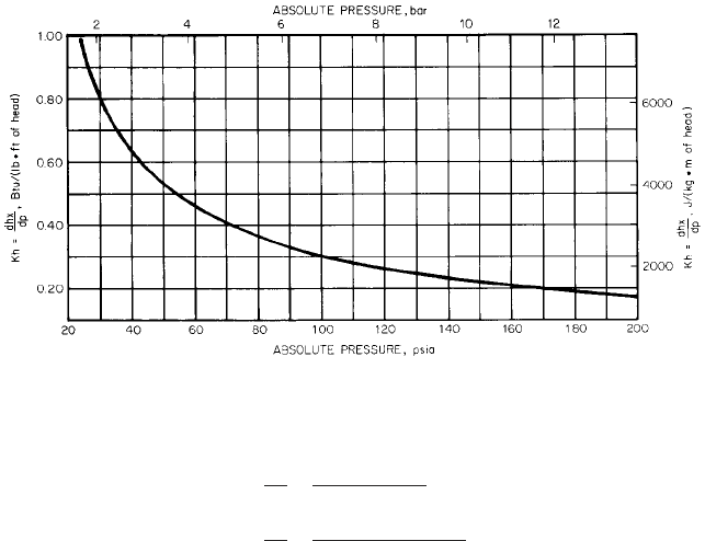
K
h
change in enthalpy with pressure at steam conditions prior to load reduc-
tion, Btu/lb • ft absolute pressure (J/kg • m) (Figure 8)
H
x
available excess NPSH NPSH available NPSH required, ft (m)
This relationship is somewhat conservative and does not take into account the resi-
dence time of the condensate in the piping and the closed heaters between the condenser
hot well and the direct-contact heater. A slightly less conservative formula that takes some
account of this residence time is
(2)
where h
c0
enthalpy of condensate to heater under initial conditions, Btu/lb (J/kg)
For example, let
Initial heater pressure 153 lb/in
2
(10.5 bar)
Initial feedwater temperature 360°F (182°C)
Initial feedwater enthalpy 331.4 Btu/lb (770.8 kJ/kg)
Final condensate enthalpy 82.95 Btu/lb (192.9 kJ/kg)
K
h
(from Figure 8) 0.22 Btu/lb/ft (1679 J/kg/m)
H
x
(available excess NPSH) 15 ft (4.57 m)
Minimum
Q
h
Q
s
h
x0
31h
c0
h
c2
2>24
K
h
H
x
Minimum
Q
h
Q
s
h
x0
h
c2
K
h
H
x
9.5 STEAM POWER PLANTS 9.81
FIGURE 8 Enthalpy change with change of vapor pressure, for water
Then
in USCS units
in SI units
This means that for safe operation after a sudden load drop in this particular ease, the
heater storage volume must be at least 75.3 times the volume of the suction piping.
More complex and more rigorous calculations of the minimum ratio of heater storage
volume to suction piping volume are provided in Reference 1.
Even where analysis indicates that the boiler-feed pumps are assured of their required
NPSH during a reduction in turbine load, there is no guarantee that their operation will
not be interrupted by flashing at some point in the suction piping. The criterion in deter-
mining the probability of flashing in the suction piping is to consider that the water that
left the heater outlet at a saturated condition must pick up static pressure, by means of the
vertical drop, at a rate at least equal to the pressure decay rate of the heater, or it will flash.
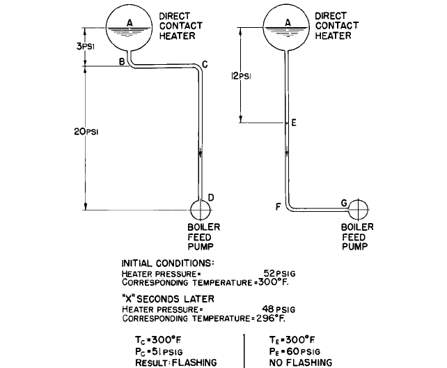
The most adverse conditions are those introduced by locating a horizontal run of pip-
ing too close to the heater outlet. A typical case is illustrated in Figure 9. (Because this
example is used merely to illustrate the unfavorable effect of such a piping layout, the unit
system used is immaterial and the example has been expressed in USCS units.) In the
comparison of the two installations, we will stipulate that the total length and the sizes of
the piping are the same for both arrangements and that the volumes of the suction piping
between the heater outlet and points C and E of the two arrangements are the same. To
simplify the comparison, the vertical distances between A and B, B and D, and A and E
have been expressed in pounds per square inch instead of feet.
If a time interval x is selected such that water having left the heater outlet at the start
of the transient conditions will have reached points C and E, respectively, at the end of the
time interval, it becomes apparent that in the case illustrated on the left side of Figure 9,
the pressure gain at point C is only 3 lb/in
2
by virtue of the vertical drop. Thus, x seconds
after a pressure drop in the direct-contact heater from 52 to 48 lb/in
2
gage, the pressure at
point C will be 51 lb/in
2
, which is below the vapor pressure at the new temperature
(296°F), and so flashing will occur. On the other hand, in the case of a straight vertical drop
(right side of Figure 9), after the same time interval x the pressure will be 60 lb/in
2
, which
exceeds the vapor pressure, and so no flashing will occur. Formulas 1 and 2 can be used to
Minimum
Q
h
Q
s
770,800 192,900
1679 4.57
75.3
Minimum
Q
h
Q
s
331.4 82.95
0.22 15
75.3
9.82 CHAPTER NINE
FIGURE 9 Comparison of suction piping arrangements
determine the adequacy of the piping layout by selecting the critical point in the piping (in
this case, point C) and substituting in the formulas so Q
s
volume in suction piping to
point C and H
x
static head to point C less frictional losses to point C.
In the event that circumstances do not permit the provision of sufficient NPSH mar-
gin to provide adequate protection to the boiler-feed pumps during a sudden turbine load
reduction, two alternate means are available to compensate for these circumstances:
1. A small amount of steam from the boiler can be admitted to the direct-contact heater
through a pressure-reducing valve, to reduce the rate of pressure decay in the heater.
2. A small amount of cold condensate from the discharge of the condensate pumps can
be made to bypass all or some of the closed heaters and be injected at the boiler-feed
pump suction to subcool the feedwater, thus providing additional NPSH margin
during load reduction.
Figure 10 illustrates the effect of subcooling (or temperature depression) on the avail-
able NPSH at various initial feedwater temperatures. Figure 11 shows, for varying ratios
of injection flows, the temperature depression resulting from cold water injection plotted
against the difference in temperature between the feedwater and the injection stream. For
instance, if it were desired to provide 20 ft (6.1 m) additional NPSH to a boiler-feed pump
that handles 325°F (163°C) water, the required temperature depression is 6°F (3.3°C). If
the injection water temperature is 190°F (87.8°C), the difference between feedwater and
injection water temperature is 135°F (75.2°C). From Figure 11, we can see that the injec-
tion flow must be 4.5% of the total feedwater flow.
An analysis of the relative merits of the two methods of protecting boiler-feed pumps
against the unfavorable effects of transient conditions is presented in Reference 2. Either