Pump Handbook by Igor J. Karassik, Joseph P. Messina, Paul Cooper, Charles C. Heald - 3rd edition
Подождите немного. Документ загружается.

9.2 SEWAGE TREATMENT 9.41
Level Control With level control, each pump is turned on and off at specific water lev-
els in the suction wet well; in the case of variable-capacity pumps, the level control
attempts to maintain a preset level, once started. Pumps turn on with a rising level and
off as the level lowers. Level control is generally used in raw sewage pumping applica-
tions. In this manner, it is possible to match discharge with incoming flow.
Flow Control Flow control is used sometimes where there is no limitation on the avail-
ability of flow to the pump suction and where it is desirable to maintain a predetermined
rate of discharge. Where flow control is used, a flowmeter is used as the primary instru-
ment to measure flow and to serve as a basis for varying pump speed, which in turn con-
trols capacity. The speed can be changed either manually or automatically through
closed-loop instrumentation.
Additional Level Control Low-water pump cutoff and high-level alarm are provided on
most pumping installations. The low-level cutoff is required to prevent the pumps from
running dry, and the high-level alarm notifies the operator in the event the pump should
fail to operate. When the pump stops because of low-water cutoff, there is usually some
means of indicating this to the operator.
MISCELLANEOUS DESIGN CONSIDERATIONS____________________________
In addition to the matters discussed previously, there are certain other items that should
be given consideration in the design of pumping installations.
Piping and Valves Suction and discharge piping should normally be sized so the max-
imum velocities do not exceed 5 and 8 ft/s (1.5 and 2.4 m/s), respectively. Higher veloci-
ties, however, may be justified by economic analysis for particular installations. Lines less
than 4 in (102 mm) in diameter should not be used for raw sewage. Preferably, sludge lines
should be at least 6 in (152 mm) in diameter; 4-in (102-mm) lines are sometimes used for
dilute biological sludge.
Valves should be installed as required on the suction and discharge sides of each pump
to allow removal and maintenance of individual pumping units without disturbing the
function of the remainder of the installation. It is customary to use either ball or plug
valves on raw sewage and concentrated sludge applications. Either plug or butterfly
valves can be used for settled sewage or for dilute sludge.
Piping should be designed with sufficient flexibility to avoid stress on the pump
flanges. Flange-coupling adapters are sometimes used for this purpose on both the suction
and discharge sides of the pump.
Surge Control Careful attention should be given to surge control wherever a pump dis-
charges into a force main of appreciable length. Generally this is a problem only in the design
of raw sewage pumping stations located within the collection system.Changes in fluid motion
caused by starting or stopping of pumps or by power failure can create surge conditions.
Surges caused by normal starting and stopping of pumps driven by electric motors
may be controlled (1) by selecting individual pump capacities such that the change in
velocity in the system when a single pump starts or stops will not result in excessive
surges, (2) by using variable-speed drives to bring pumps gradually on or off line, or (3) by
using power-operated valves that are controlled so the pumps are started and stopped
against a closed valve.
Surges caused by power failure can be controlled by devices designed to open on an
increase in pressure, by devices that will exhaust sewage from the system upon sudden
pressure drop in anticipation of surge, or by a surge tank.
Pump Seals Most sewage and sludge pumps can be obtained with either mechanical
seals or packed stuffing boxes. Conventional mechanical seals have the disadvantage of
requiring a pump to be disassembled so the seal can be repaired. Present mechanical seal
9.42 CHAPTER NINE
technology offers a solution to this in the form of a split mechanical seal. Such a seal can
be removed and repaired or replaced without the necessity of disassembling the pump-
ing unit.
Often it is easier to replace the seal rather than repair it, and it is desirable to keep a
spare on hand for this purpose. Packed stuffing boxes provided with water-sealed lubrica-
tion are still the most common choice for non-submersible sludge and sewage pumps.
Grease seals are sometimes used for some of the smaller sewage pumps that do not run
continuously.
Water serves multiple purposes as a sealing medium: it seals, lubricates, and flushes.
Flushing is particularly important where abrasive material is involved in that it helps pre-
vent this material from entering the seal. Grit and ash are very abrasive, and either will
cut the shaft sleeves in a relatively short time.Where pumps are controlled automatically,
a solenoid valve interlock with the pump starting circuit should be provided in the seal
water connection to each pump. A manual shutoff valve and strainer should be provided
on each side of each solenoid valve, and a bypass line should be provided around it.
Mechanical seals are normally lubricated with a clean external water source supplied
at a pressure and flow rate as recommended by the seal manufacturer. Seals can be lubri-
cated by the product being pumped provided it is filtered and can provide a reliable pres-
sure and flow rate to the seal cavity. In such cases, a connection is normally provided
between the pump discharge and the seal with a 0.10 to 0.20 in (2.5 to 5 mm) in-line filter
to prevent foreign material from entering the seal cavity.
Occasionally, a pump station is so remote that sealing water is not readily or econom-
ically available. Mechanical seals can be provided constructed of special materials to with-
stand such adverse conditions. Also, several types of “formed-in-place” packing are
available that do not require a smooth surface on which to seal as the packing develops its
own sealing surface. However, these packing materials are not normally recommended for
temperatures over 130°F (54°C) or pressures over 60 lb/in
2
(4 bar).
Pump Bearings Pump bearings must be adequate for the service and should be
designed on the basis of not less than a minimum life of five years in accordance with the
Anti-Friction Bearings Manufacturers Association life and thrust values. The larger
sewage pumps are usually equipped with both case and impeller rings of bronze or
chrome steel.
Cleanout Ports Pumps should be provided, where possible, with cleanout ports on both
the suction and discharge sides of the impeller. These are desirable for inspection and
maintenance purposes.
Wet-Well Design Raw sewage wet wells should not be so large that sewage is retained
long enough to go septic. It is usually desirable to limit storage to a maximum of 30 min-
utes. Shorter retention time is desirable. With the variable-speed controls now available,
many stations can be designed so that the pumping rate matches the inflow rate and the
inherent difficulties of frequent pump cycling or long retention times in wet wells can be
avoided.
FURTHER READING __________________________________________________
American Society of Civil Engineers. Design and Construction of Sanitary and Storm Sew-
ers. Manual and Report on Engineering Practice No. 37, WPCF Manual of Practice No. 9,
New York, 1969, pp. 287
—
331.
Benjes, H. H. “Design of Sewage Pumping Stations.” Public Works, August 1960.
Benjes, H. H. “Sewage Pumping.” J. Sanit. Eng. Div., Proc. ASCE, June 1958.
Great Lakes-Upper Mississippi River Board of State Sanitary Engineers. Recommended
Standards for Sewage Works. Health Education Service, Albany, NY, 1978.
Parmakian, J. Water Hammer Analysis. Prentice-Hall, Englewood Cliffs, NJ, 1955.
9.2 SEWAGE TREATMENT 9.43
Rich, G. R. Hydraulic Transients. 2nd rev. ed., McGraw-Hill, New York, 1963.
Sanks, R. L. Pumping Station Design, Butterworths, Stoneham, MA, 1989.
Water Pollution Control Federation: Design of Wastewater and Stormwater Pumping Sta-
tions, WPCF Manual of Practice No. FD-4, Washington, DC, 1980.
Water Pollution Control Federation. Safety and Health in Wastewater Systems, WPCF
Manual of Practice No. 1, Washington, DC, 1983.
Water Pollution Control Federation. Wastewater Treatment Design, WPCF Manual of
Practice No. 8, Washington, DC, 1977.

JOHN S. ROBERTSON
9.45
SECTION 9.3
DRAINAGE AND
IRRIGATION
DRAINAGE PUMPS ___________________________________________________
Drainage pumps are used to control the level of water trapped in a protected area. Entrap-
ment occurs when high lake levels, stream stages, and tides preclude the normal discharge
of streams, storm runoff, and seepage from the protected area. These high-water condi-
tions are created by floods and hurricanes or impoundment.
Floods and hurricanes occur infrequently and are relatively short-lived. However, as
normal drainage is not possible at such times, all interior drainage that cannot be ponded
must be pumped over the protective works if the protective works is a levee or through it
if it is a concrete flood wall. Pumps for this purpose are strategically located at the edge of
pending areas and streams, in sewer systems, or in the protective works. These pumps are
operated continuously or are cycled on and off as necessary to maintain the water level in
the protected area below the elevation at which damage would be experienced. As their
use is required only during emergency situations and usually under adverse weather con-
ditions, reliability of operation is essential.
Where valuable low-lying areas must be protected against inundation due to backwa-
ter, gravity drainage from the area is generally not possible. In such situations, all seep-
age and storm-water runoff entering the protected area must be pumped. The pumping of
seepage is often a continuous operation, whereas the pumping of storm-water runoff is
intermittent. Both can occur simultaneously because inflow due to seepage does not stop
during a rainstorm. It therefore is necessary to provide pumps that can handle seepage
and storm water simultaneously.
IRRIGATION PUMPS __________________________________________________
Irrigation pumps play an important part in making vast areas of arid and semiarid land
agriculturally productive. These pumps take water from surface sources, from subsurface
9.46 CHAPTER NINE
sources, and in ever-increasing amounts from sewage treatment facilities and pump it to
the point of application.
Water from surface sources, such as streams, lakes, and ponds, is pumped directly into
the distribution system or into a conveyance system. If pumped into a conveyance system,
it flows either by gravity or under pressure to the distribution point or to a booster pump-
ing station. Most of the pumps used in these installations are mounted permanently and
are arranged to operate as necessary without constant attendance during the growing
season.
Water from subsurface sources is usually pumped directly into the distribution system.
In such installations, a well is drilled in the vicinity of the area to be irrigated and is fit-
ted with the proper size pump. In many instances, more than one well is needed to provide
the required capacity.
Effluent waters from different types of sewage treatment facilities are sometimes used
for irrigation on a year-round basis in land disposal systems. In these systems, the treated
effluent is temporarily stored in holding tanks or ponds and is applied to the disposal area
at predetermined rates via sprinkler systems. As the disposal area may be a considerable
distance from the storage area and as pressure is needed for operation of the sprinkler sys-
tem, pumping is required.
PUMP TYPES ________________________________________________________
Centrifugal pumps are used almost exclusively in drainage and irrigation installations.
Because of the large selection of propeller, volute, turbine, and portable pumps manufac-
tured today, there is little difficulty in finding a pump that will meet the conditions
encountered in these fields. Pumps in the sizes needed to meet the requirements of the
majority of installations are available as standard items. Specialized pumps and
extremely large pumps are designed and built to meet the needs of individual projects.
Propeller Pumps These units are used for low-head pumping. As most of the pumping
in drainage and irrigation is low-head, the propeller pump is the most widely used type.
In general, vertical single-stage axial- and mixed-flow pumps are used; however, there are
instances where two-stage axial-flow pumps should be considered for economic reasons.
Horizontal axial-flow pumps are used for pumping large volumes against low heads
and usually employ siphonic action when not of the submersible type. When higher heads
are involved, these pumps can be arranged to operate with siphonic action until the back
pressure places the hydraulic gradient above the pump.
Variable-pitch propeller pumps rotating at constant speed can be operated efficiently
over a wide range of head-capacity conditions by varying the pitch of the propeller blades.
These pumps are used when the head-capacity conditions cannot be met with the more
economical fixed-blade pumps and where the pumps will be operated often enough and
long enough to warrant the expense. The blade-control system needed for such pumps is
more sophisticated than in any of the systems usually provided on drainage and irrigation
projects. As a consequence, operation and maintenance must be performed by organiza-
tions employing competent and experienced personnel.
Volute Pumps Volute pumps are used when pumping from surface sources and in gen-
eral when the total head exceeds approximately 45 ft (14 m). Such pumps are available
in many types, such as vertical and horizontal shaft, end suction, bottom suction, and dou-
ble suction with semi-open or closed impellers, and so on. These pumps are mounted in
dry pits when located below grade and on slabs or floors when located above grade. The
particular type used depends on the capacity and kind of service to be performed.
Deep-Well Turbine Pumps Deep-well turbine pumps (vertical-shaft, single-suction
pumps having one or more stages) are used in irrigation primarily to pump water from a
subsurface source into a distribution system. The head against which the pump will oper-
ate determines the number of stages that must be provided. For large capacities, more
than one pump will be needed.
9.3 DRAINAGE AND IRRIGATION 9.47
Submersible Turbine Pumps In these deep-well units, the motor is close-coupled to the
pump and submerged in the well. This type of pump is used for high-head applications
where long intermediate shafts are undesirable.
Portable Pumps In drainage work, portable pumps are used as emergency equipment
to control ponding elevations where mobile equipment, such as tractors and trucks, hav-
ing power takeoffs are available to drive them. In irrigation work, they are usually used
to irrigate from a surface source. Such pumps are small-capacity, low-head, economical
pumps that must be submerged in order to be used.
PUMP SELECTION ___________________________________________________
A pump selection study should always be made, and its importance cannot be emphasized
enough. Such studies permit selection of the type of pump and discharge system best
suited to the project and provide the information needed to proceed with the design of the
installation.
In many cases, the type of pump required will be obvious. If more than one kind of
pump would be satisfactory, the specifications should permit the pump manufacturer to
make the choice. This is particularly advantageous when competitive bidding is involved.
The practice of the Corps of Engineers in this regard is to write a performance specifica-
tion and allow the pump manufacturer to determine the type, size, and speed of the pump.
Before initiating such a study, all previous studies made to determine the total pump-
ing requirement or station capacity, pertinent water-surface elevations, terrain, utility
locations, proposed station or well locations, points of discharge, and the proposed method
of operation should be reviewed. Also to be considered is the experience of the personnel
that will be responsible for the operation and maintenance of the installation.
Number of Pumps First costs are generally of more concern than operating costs in
drainage and irrigation work because the operating period for the majority of installations
is relatively short and occurs only once a year. Costs can be minimized by using as few
pumps as possible. However, one-pump installations are seldom used except in the case
of wells. For reliability, a minimum of two pumps should be installed in drainage pump-
ing stations, where the loss of even one pump during an emergency situation could result
in considerable damage. Three or more pumps are preferred. Standby units are provided
only in those installations where continuous operation precludes taking a pump out of ser-
vice for maintenance.
The number of pumps ultimately used should be consistent with the demands of the
project. For instance, when the installation is located in an agricultural area or is a part
of an urban sewer system, a standby pump should be provided because these installations
must always be capable of discharging project requirements during periods of blocked
drainage. In this way, considerable damage may be avoided. When the installation is used
to pump storm water from pondage or irrigation water from a lake, the loss of a pump is
not critical and so a standby pump is not needed.
If during pump selection it is found that the rated power of the prime mover exceeds
the maximum power requirements of the pump by a considerable amount, the contem-
plated number of pumps should be increased or decreased, provided the change results in
a better power match without increasing the overall cost of the installation. By increasing
the number of pumps and thereby reducing the required power, there is a possibility that
the size of the prime mover can be reduced and that the pump power will approach the
rated power of the prime mover. On the other hand, decreasing the number of pumps will
increase the power requirements. This increase may be sufficient to either utilize most of
the excess capacity in the prime mover or require the use of a larger one.
For installations requiring the use of large pumps, foundation conditions become
important. To prevent the installation from being relocated to a less desirable site or the
necessity of providing a more expensive pile foundation because the bearing pressures at
9.48 CHAPTER NINE
the selected site exceed the allowable limit, the number of pumps should be increased, pro-
vided the loading can be reduced to an acceptable amount and the resulting installation
continues to be the most economical.
Inadequate depth on the suction side of the pumps may necessitate the use of more
pumps. Should the water not be deep enough to provide the submergence needed by the
contemplated pump, more pumps of a smaller size may have to be used or the sump and
approach channel may have to be excavated to the needed depth. The latter alternative
could cause operational and maintenance problems and might be the more expensive
solution.
Capacity The capacity of a pump is a function of the total pumping requirement, the
number of pumps, and, in the case of wells, the capacity of the well. Whenever possible,
all pumps in a multiple-pump installation should be of the same capacity. This is advan-
tageous from a cost standpoint as well as from a maintenance standpoint. In drainage
installations, three pumps are generally provided in order to have the capability of pump-
ing not less than two-thirds of the project requirement with one pump inoperative. Each
pump would then have a capacity equal to one-third of the total capacity. When more than
three are used, the capacity should be the total required capacity divided by the number
of pumps being used. If two pumps are used, each pump should be sized to pump not less
than two-thirds of the total capacity.
In irrigation installations utilizing multiple pumps, the capacity of each pump should
be the same. In single-pump installations, the pump should be sized to meet project
requirements.When wells are involved, the capacity of the pump will be determined by the
capacity of the well. Often several wells are needed to give the capacity to satisfy the
established requirements.
When a standby pump is to be provided, its capacity should be equal to that of the
largest pump being furnished.
Head Total head is the algebraic difference between the total discharge head and the total
suction head. In drainage and irrigation work total suction head can usually be determined,
but this is not always the case for the total discharge head. The losses in the discharge sys-
tems often must be determined by hydraulic model test rather than by calculation and
therefore must be estimated for preliminary selection purposes.The head specified will have
to be some head other than total head; generally pool-to-pool head is used.
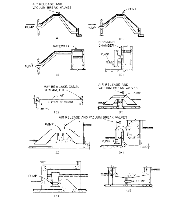
Total discharge head is defined in the Hydraulic Institute Standards, and its value is
to a great extent determined by the type of discharge system used. A number of the many
possible discharge systems used are shown in Figure 1. The losses in systems A, B, C, D,
and E can be calculated. Thus the performance for pumps discharging into these systems
can be put on a total head basis.
System A is an “over the levee” siphonic discharge line, the use of which can seldom be
justified. However, continuous operation over long periods could effect a savings that
would be sufficient to justify the additional cost of the installation and the taking on of the
operational hazards usually encountered with such lines. The total discharge head for this
system is equal to the height of the discharge pool, stream, or lake above the impeller plus
the exit loss and the discharge line losses from the pump discharge nozzle to the line ter-
minus. The absolute pressure at the high point of the line should be not less than 9 ft
(2.7 m). Lower values have been used successfully, but this should be the exception rather
than the rule. For additional information on the determination of heads in a siphonic sys-
tem, refer to “Siphon Head” in Section 8.1.
Flap valves should be installed on the discharge end of all lines subjected to a cycling
operation. The closing of these valves following pump shutdown prevents reverse flow into
the protected area and permits development of the pressures needed to keep the lines full
(primed) during those short periods when pumps are idle. These pressures will be less
than atmospheric pressure, with the minimum pressure (absolute) being at the high point.
Should there be significant leakage at the joints or in the valves, the pressures will rise
and the water level at the high point will drop. If the water level drops below the invert of
the line at the high point, the two legs of the line will be separated by an air space and
priming will be necessary when the pump is started.
9.3 DRAINAGE AND IRRIGATION 9.49
FIGURE 1A through J Discharge systems (adapted from Department of the Army, “Mechanical and Electrical
Design of Pumping Stations,” EM 1110-2-3105, Washington, DC, 1962)
Air-release valves should be installed at the high point of all siphonic discharge lines
to provide an escape for the air being compressed as the water rises in the line during
priming, and vacuum-break valves should be used to prevent reverse flow into the pro-
tected area. For lines equipped with flap valves, the vacuum-break valve should be man-
ually operated and used when the flap gate fails to seat properly or to provide a rapid
means of draining the line when pumping is no longer required. Units for almost any size
line can be obtained from manufacturers who specialize in such equipment or they can be
assembled, using swing check and angle valves.
System B in Figure 1 is an “over the levee” nonsiphonic discharge line. To preclude
siphonic action, this line should be vented at the high point with a vent having a diame-
ter that is approximately one-fourth that of the line. The invert of this line at the high
point should be placed at the same elevation as the top of the protective works so the
pumped flow can discharge from the down leg of the line under gravity without backwa-
ter effects for all discharge pool elevations up to maximum. Thus the total discharge head
9.50 CHAPTER NINE
will have a constant value because it will not be affected by changes in the level of the dis-
charge pool. To ensure adequate prime mover capacity when using this system, it is the
practice in all cases to use the top of the line at the high point in lieu of the hydraulic gra-
dient when determining the total discharge head. Therefore, total discharge head is the
height of the top of the line at the high point above the impeller plus the velocity head in
the line at the high point based on a full pipe and the losses in the line from the pump dis-
charge nozzle to the beginning of the down leg of the line.
System C is used when there is a conduit carrying the normal gravity discharge under
the levee adjacent to the station that must be valved off against reverse flow into the pro-
tected area during periods of high water. The closure gate is located in a gate well con-
structed on the stream or lake side of the levee to prevent subjecting the gravity conduit
to high-water conditions. The pump discharge lines go over the levee and terminate in the
gate well above the maximum water level. This shortens the lines and reduces the cost.
The total discharge head for this system is equal to the height of the top of the line at the
terminal end above the impeller plus the exit loss and the losses in the line between the
pump discharge nozzle and the terminal point. The total discharge head for this system,
as in system B, is independent of the discharge pool and therefore constant. Neither flap
valves nor vents are required on these lines.
System D is used when the pumping station is constructed as an integral part of the
levee or flood wall. The invert of the pump discharge line is placed at an elevation that is
above the stream or lake level that will prevail approximately 70% of the time or as is dic-
tated by the physical dimensions of the pump. Owing to the extreme turbulence in the dis-
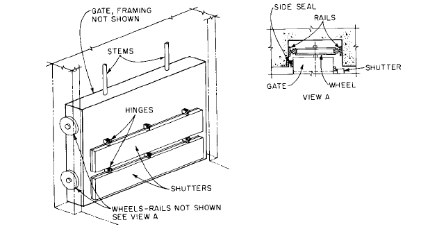
charge chamber, gates with multiple shutters, which are less likely to be damaged, should
be used instead of flap gates on discharge lines that are larger than 36 in (914 mm) in
diameter. When the water level in the discharge chamber is below the top of the discharge
line, the total discharge head is determined in the same manner as for system C. For
higher discharge water levels, the total discharge head is equal to the height of the water
level in the discharge chamber above the impeller plus the exit loss and the losses between
the pump discharge nozzle and the chamber side of the flap valve.
System E is perhaps the most common discharge system in use today. It is used to con-
nect one pump or several manifolded pumps with a lake, canal, stream, ditch, reservoir, or
sprinkler system. For short lines and low static heads, valve and fitting losses, frictional
losses, and exit losses are very important, whereas in long lines or very high static head
installations only frictional losses are given consideration. In manifolded installations
using propeller pumps, a check valve and gate valve are installed immediately down-
stream of the pump. The gate valve should always be opened before the pump is started
because the motors provided are not usually sized to operate against shutoff head. Positive
shutoff valves are placed immediately downstream of volute or turbine pumps because
these pumps are usually started and stopped against a closed valve. They also prevent
reverse flow into the sump when one of the pumps is inoperative.
Pool-to-pool head is the difference in elevation between the sump and discharged-water
surfaces and is used instead of total head in drainage work because the losses in the dis-
charge system are not easily determined. Installations of this type are exemplified by sys-
tems F, G, H, I,and J in Figure 1. For such installations, it is best to specify the pumps on
a pool-to-pool basis, to have the pump manufacturer design the pump and the discharge
system, and to verify the predicted performance by model test. It should be noted that in
such installations the discharge systems are usually constructed within the confines of the
pumping station structure.
System F is operated as a siphon with the pump supplying energy equivalent to the
pool-to-pool head plus the system losses.The invert of the pump discharge pipe at the high-
est point is located above the maximum river stage, and vacuum pumps are generally used
to aid in priming the pump. This system is used for pool-to-pool heads of up to approxi-
mately 6 ft (1.8 m) and where the physical dimensions of a vertical pump would make it
necessary to operate against higher heads. In estimating the losses, entrance losses, which
are small [approximately 0.14 ft (4 cm)], should be neglected. The centerline of the suction
piping should be assumed to make an angle of 45º with the horizontal, and the diameter of
the discharge piping as measured at the discharge flange of the discharge elbow should be
such that the velocity at maximum discharge is approximately 12 ft/s (0.037 m/s) or less.
9.3 DRAINAGE AND IRRIGATION 9.51
FIGURE 2 Multiple-shutter gates
System G is used for pool-to-pool heads of up to approximately 15 ft (4.6 m). The water
passages change in cross-section from round at the pump bowl to rectangular at each end.
The width at the suction end is the same as or less than that of the suction bay, and the
height is such that the entrance to the suction passage is always submerged when the
pump is in operation. The discharge velocity should be kept to approximately 6 ft/s (1.8
m/s). Multiple-shutter gates (Figure 2) arranged to be raised when the pump is in opera-
tion are provided to prevent prime mover overload when the pump is started and to pre-
vent reverse flow when the pump is stopped or inoperative.These pumps are usually large
and slow and require substantial prime movers. Vacuum priming equipment is used so
additional power will not be required for priming.
System H is essentially the same as system G, except that the former is used for pool-
to-pool heads up to approximately 26 ft (7.9 m). Also, a splitter may be required in the dis-
charge water passage for structural purposes as well as for keeping the multiple-shutter
gates to a reasonable size. The pumps used with this system are vertical and in general
smaller than those used with system C.
System I can be constructed with the lip of the pump column either above or below the
design flood elevation or the maximum surge, if it is being provided for hurricane protec-
tion. If the lip of the pump column is above and the chances of reverse flow through the
pumps are extremely remote, gating of either the pump column or the discharge water
passage is unnecessary. If the lip of the pump column is below, a decision of whether to
gate both the pump column opening and the discharge water passage or just the water
passage must be made. In general, if the pumps will be in operation continuously during
high-water conditions and if reverse flow through an inoperative pump will not have sub-
stantial detrimental effects, only the multiple-shutter gate at the end of the discharge
water passage need be provided. Reverse flow could occur should the flap for some reason
fail to close. Like system C, splitter walls may be required if pumps are large. Also, the
clearance between the lip of the pump column and the ceiling of the discharge water pas-
sage is critical and should be determined by model test.
The shape of the pump column lip will also affect pump efficiency and should be deter-
mined by test.
System J could have many configurations but, regardless of arrangement, would have
to be gated on the suction side with a positive shutoff gate, such as a pressure-seating slide
gate, and on the discharge side with a positive shutoff gate and a multiple-shutter gate or
a flap gate if the installation is small and a pipe is used in place of formed water passages.
When formed water passages are used, transition sections between the pump and the
gates sections will be needed and should be designed by the pump manufacturer.