Pump Handbook by Igor J. Karassik, Joseph P. Messina, Paul Cooper, Charles C. Heald - 3rd edition
Подождите немного. Документ загружается.

9.2 SEWAGE TREATMENT 9.31
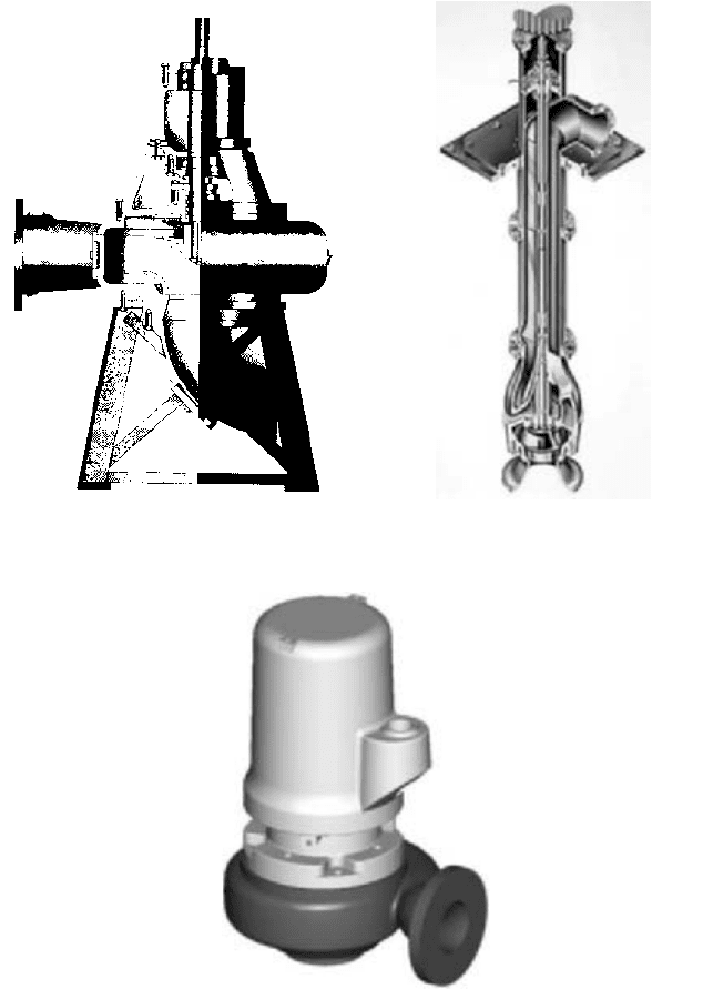
FIGURE 4a Non-clog dry pit sewage pump
(Flowserve Corporation)
FIGURE 4b Solids handling wet pit pump
(Flowserve Corporation)
FIGURE 4c Non-clog submersible sewage pump (Flowserve Corporation)
Although non-clog pumps 8 in (203 mm) and small are available with self-priming (Sec-
tion 2.4), most conventional sewage pumps are located so the impeller is always below water
level in the suction wet well. This eliminates the need for specialized priming systems.
Self-priming pumps have been used successfully to pump raw unscreened sewage, par-
ticularly in the southern part of the United States.The self-priming feature eliminates the
9.32 CHAPTER NINE
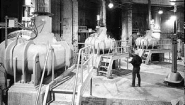
FIGURE 5 Vertical sewage pumping units at the South System Pump Station, Deer Island in Boston, MA
containing (8) 36 in (915 mm), 46,300 gpm (10,510 m
3
/h) pumps driven by 1250 hp (932 kW) variable speed motors
(Flowserve Corporation)
dry-pit cost and gives the centrifugal pump the gas-handling advantage of positive dis-
placement pumps. Operating costs are higher, though, because the design efficiencies gen-
erally run about 10 to 15% lower than for the conventional nonclog units.
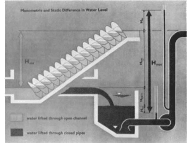
Archimedean screw pumps (Figure 6) are occasionally used for raw sewage pumping
applications.These units are advantageous in that they do not require a conventional wet
well, and they are self-compensating in that they automatically pump the liquid received
regardless of quantity as long as it does not exceed the design capacity of the pump. This
is done without the need for variable speed drive equipment. Also, as shown by Figure 6,
the total operating head of a screw pump installation is less than for those pumps that
require conventional suction and discharge piping. Screw pumps, however, have a practi-
cal limitation as to pumping head. Generally speaking, they are not used for lifts in excess
of 25 ft (7.6 m).
Settled Sewage Settled sewage pumps are used to lift partially or completely treated
waste from one part of the plant to another or to the receiving stream. In Figure 3, these
pumps are the settled sewage pump, service water pump, and decantate return pump.
The liquid to be handled usually contains some solids, but grit and most of the rags and
other stringy material have already been removed. Sufficient firm capacity should be pro-
vided to meet peak flow requirements. In no case should fewer than two units be provided.
Wet pit solids handling or diffuser pumps (Subsection. 2.2.1) are commonly used for the
pumping of settled sewage. Depending on the total head conditions and degree of solids
removal, a diffuser pump selection may be of either the propeller or mixed-flow design.
However, solids-handling wet pit pumps are gaining in popularity due to their greater
freedom from clogging. Although normally installed in wet-pit applications, these units are
sometimes mounted on suction piping and installed in a dry pit. Either type of application
is acceptable, although economics usually dictates a wet-pit installation. Head and capac-
ity conditions will determine which type of unit is applicable.
Conventional sewage pumps may also be used to pump settled sewage.They may be of
the dry pit, wet pit, or submersible type. It is not usually as economical to design a dry pit
for this application, but it is acceptable as far as suitability of equipment is concerned.
Archimedean screw pumps can be used to pump settled sewage, provided the lift is not
excessive. As previously noted, this type of pump has certain inherent advantages.
9.2 SEWAGE TREATMENT 9.33
FIGURE 6 Archimedean screw pump (U.S. Filter/Zimpro)
Service Water Plant effluent water is frequently used for flushing, gland seal, foam con-
trol sprays, chlorine injector operation, lawn sprinkling, fire protection, and various other
services in a waste-water treatment plant. Except for the fact that some solids must be
contended with, this application is much the same as that found in building-water sup-
ply and small distribution systems.
Screening of solids is normally required; this can be accomplished either before or after
the pumps, depending upon various circumstances. Pipeline-type strainers are recom-
mended as they are not only economical but require a minimum of space, can be auto-
matically backflushed, and are much easier to operate than alternative equipment.
Any type of conventional volute or diffuser clear-water pump can be used on service
water applications, provided the effluent water is screened prior to entering the pump.
Pumps capable of handling some solids should be used in those instances where pre-
screening is not practical.
Sludge and Scum This classification is divided into two separate categories, based on
the concentration of solids in the liquid to be handled. Specialized pumping equipment is
required for more concentrated sludges, whereas pumping of dilute sludge and scum is
somewhat comparable to the handling of settled sewage.
DILUTE SLUDGE OR SCUM For the purposes of this discussion, dilute sludge and scum is
defined as having less than 2% solids. An exception is digested sludge recirculation, which
generally exceeds the 2% limit. This is included along with the more dilute sludges
because the same type of pumping equipment is used.
Normally, the handling of dilute sludge is limited to the transfer of biological sludge
back to the treatment process or to some other point for further concentration or dewa-
tering and disposal. When digesters are used as part of the treatment facilities, sludge is
often recirculated through external heat exchangers in order to maintain temperatures
9.34 CHAPTER NINE
conducive to anaerobic bacterial action. This recirculation also helps keep the contents of
the digester mixed. Occasionally, primary sludge and scum are handled in diluted form.
The firm capacity of dilute sludge pumping facilities should be equal to anticipated
peak loading. Biological sludge return pumps should have a capacity range from 25 to
100% of average design raw sewage flow to the plant. Digested sludge recirculation pumps
should be sized to turn over the contents of the digester frequently enough to maintain the
desired temperature. Diluted primary and waste biological sludge pumps should have suf-
ficient capacity to handle peak sludge loading at conservative solids concentrations.
Conventional sewage pumps are suitable for handling dilute sludge and scum. Either
the non-clog or mixed-flow impeller may be used, depending upon capacity requirements.
Diffuser pumps are particularly suitable for handling biological sludge that does not
contain any appreciable amount of trash or stringy material. They are not recommended,
however, for handling diluted scum or for recirculating digested sludge. Depending on
capacity requirements, diffuser pumps may be of either the mixed-flow or propeller
design. Wet-pit applications are most common, although dry-pit installations are occa-
sionally used.
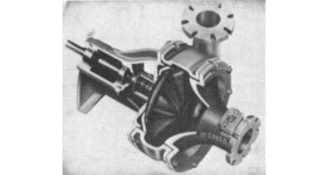
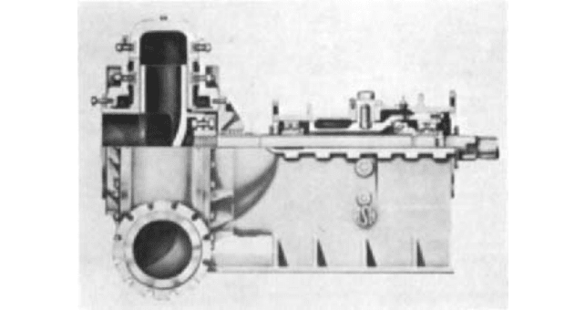
Torque flow (or vortex) pumps (Figure 7) are often used to handle dilute sludges that
contain some grit. These units are particularly suitable for this type of service because
their design is such that close running tolerances are not required; this allows the use of
specially hardened materials, such as high-nickel iron, which are not easily machined.The
most common applications of torque flow pumps are for the pumping of nondegritted
dilute primary sludge to gravity thickening and the recirculation of digested sludge.
Screw pumps can be used in certain instances for handling biological sludge. Use of
screw pumps is generally limited to low to medium lifts and to those instances where the
point of discharge is close to the sludge source.
Air-lift pumps are suitable for transferring biological sludge where the lift is small and
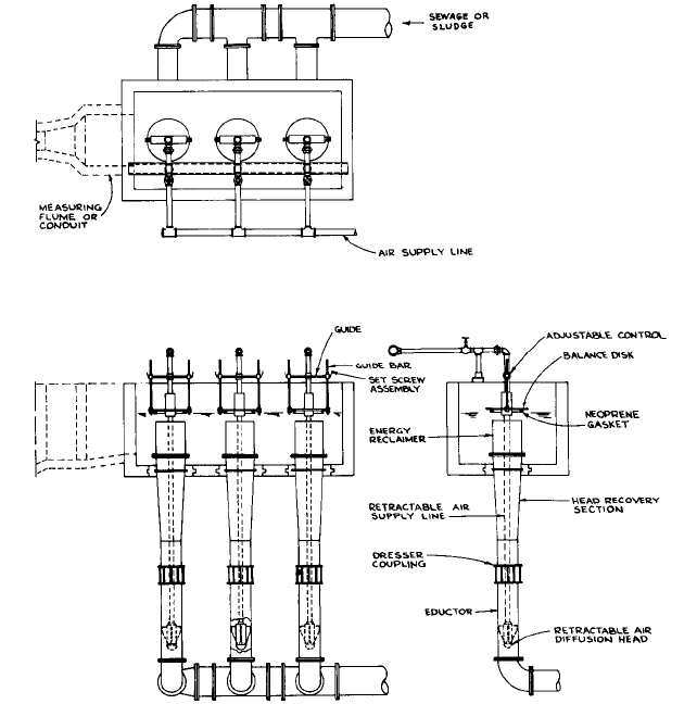
the point of discharge nearby. A typical air-lift pump installation is shown in Figure 8.
Total head should not exceed 4 to 5 ft (1.2 to 1.5 m). The ability of an air-lift pump to vary
capacity is somewhat limited, ranging from about 60 to 100% of the rated amount. These
pumps are inexpensive in first cost but have an operating efficiency of only about 30%.
They are very easy to install, and maintenance is minimal because there are no moving
parts. Air-lift pumps are commonly used to transfer sludge at package treatment plants.
CONCENTRATED SLUDGE OR SCUM Concentrated sludge or scum is defined as having more
than 2% solids. The single exception is in the case of the recirculation of digested sludge.
As previously discussed, this has been included in the dilute sludge classification.
FIGURE 7 Torque flow pump (EnviroTech Pumpsystems, a Weir Group company)
9.2 SEWAGE TREATMENT 9.35
FIGURE 8 Typical air-lift pump installation (Walker Process Equipment Division, McNish Corp.)
Each pumping installation should have enough firm capacity to handle peak design
sludge quantities while operating part-time. The proportion of operating time at peak
loading should vary from about 25% for primary sludge pumps to close to 80% for pumps
feeding dewatering equipment.
Only positive displacement pumps are recommended for handling concentrated sludge
and scum, mainly because they can pump viscous liquids containing entrained gas with-
out losing prime. Also, these materials are thixotropic, and conventional formulas for fric-
tional losses are not always valid. An arbitrary allowance of at least 25 lb/in
2
(170 kPa)
should be added to the pumping head calculated by conventional methods to allow for
changes in viscosity and partial clogging of pipelines. Positive displacement pumps are
able to maintain a relatively constant capacity regardless of variations in discharge head.
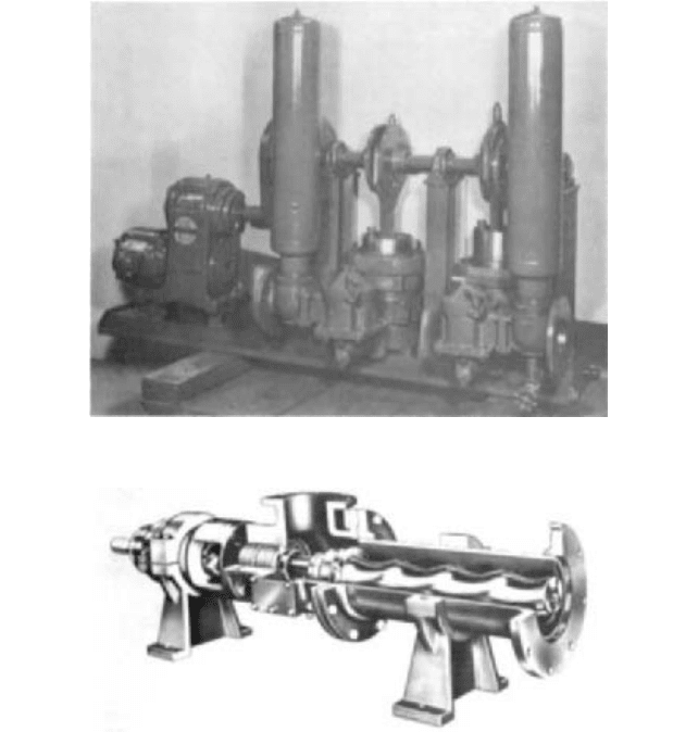
For most applications, positive displacement pumps may be of either the plunger (Fig-
ure 9) or the progressing cavity design (Figure 10).The performance of both depends upon
close running clearances; consequently they have a high incidence of maintenance, espe-
cially where gritty substances are encountered. Even so, they represent the best pumping
equipment currently available, and both designs have been used with success. Lobe-type
gear pumps have been used for specialized applications. These are to be avoided, however,
where there is any possibility that the material to be pumped will contain even a small
amount of grit.
9.36 CHAPTER NINE
FIGURE 9 Plunger-type sludge pump (ITT Marlow Pumps)
FIGURE 10 Progressing cavity sludge pump (Mono Pumps Ltd.)
Plunger pumps should be of the heaviest design available and should be rated for
capacity at about one half of full stroke. The shorter the stroke, the more stable the oper-
ation and the less maintenance required. Heads as high as 80 to 100 lb/in
2
(550 to 690 kPa)
are available and should be specified in order to give as much flexibility as possible.
Specially designed progressing cavity pumps are available for handling sewage
sludges.Wear increases along with pump speed, and so excessive speed should be avoided.
Ideally, the maximum speed of a progressing cavity pump should not exceed 350 rpm.
These units are readily available with head capabilities up to 50 lb/in
2
(345 kPa) and
should be so specified.
Certain of the newer sludge conditioning and dewatering processes, such as heat treat-
ment and pressure filtration, require pumps having a head capability in excess of 500
lb/in
2
(3450 kPa). This is extremely difficult service, and special care should be taken in
selecting the type of equipment to be used. So far, this area of application has received very
little consideration from pump manufacturers.
Other Uses Grit may be handled with reasonable success with either a torque or an
air-lift pump. Considerable flushing water is required with a torque flow pump, and to a
9.2 SEWAGE TREATMENT 9.37
FIGURE 11 Ash pump (EnviroTech Pumpsystems, a Weir Group company)
lesser extent with an air-lift unit. A special ash pump (Figure 11) is required where it is
necessary to dispose of incinerator residue in a liquid form. These units are especially
designed for ash sluicing service and are made of special hardened metals. No other pump
should be considered for this service.
PUMP SELECTION ___________________________________________________
Various factors should be considered when selecting pumping equipment. These include
the number of units to be installed, operating frequency, and station reliability require-
ments. After these factors have been fully evaluated, head-capacity curves should be pre-
pared in order to match the pumps properly with system requirements. This is necessary
because the capacity of most pumps varies with the total head at which the unit operates.
When a pump is referred to as having a certain capacity, this capacity applies to only one
point on the characteristic curve.
Number of Pumps The number of pumps to be provided at a particular installation
depends largely on the required capacity and range of flow. In considering capacity, it is
customary to provide a total pumping capability equal to the maximum expected inflow
with at least one of the largest pumping units out of service. A minimum of two pumps
should be installed in any installation except where pneumatic ejectors are used to serve
fewer than 50 houses. Two pumps are customarily installed where the maximum inflow
is less than 1.0 mgd (160 m
3
/h). At larger installations, the size and number of units should
be such that the range of inflow can be met without starting and stopping pumps too fre-
quently and without requiring excessive wet-well storage capacity. Variable-capacity
pumps can be used to match pumping rate with inflow rate.
Where variable-capacity pumps are used, a minimum of two units should be installed.
In those cases where more than one variable-capacity unit is required to handle peak flow,
three units should be installed. In this manner, it is possible to maintain a reasonable rate
of flow through each pump. Operation of a single variable-capacity pump in parallel with
a constant-capacity pump requires the variable-speed unit to operate at almost no capac-
ity whenever total inflow barely exceeds the rating of the constant-capacity unit. This is

9.38 CHAPTER NINE
extremely difficult service and should be avoided. As a general rule, pumping rates of less
than 20% of the rated capacity for which a pump is designed will result in excessive inter-
nal recirculation and unstable operation. Recirculation can occur in some pumps at more
than 50% of rated capacity. See Subsection 2.3.1.
Operating Frequency Pump size should be coordinated with wet-well design in order
to avoid frequent on-off cycling of pumps. Excessive starting will cause undue wear on the
starting equipment. Also, standard motors should not be started more than six times an
hour. Where more frequent starting is required, special motors should be provided. Inflow
into the wet well without pumping should not exceed about 30 minutes if septicity is to
be prevented.
Cycle time is defined as the total time between starts of an individual pump. It can be
determined by comparing the volume between the on and the off levels in the wet well
with the pump capacity. Cycle time is computed as follows:
In USCS units
In SI units
where CT cycle time, min
V wet-well volume between on and off levels, gal (m
3
)
D rated pump capacity, gpm (m
3
/h)
Q wet-well inflow, gpm (m
3
/h)
With a given wet-well volume and pumps having a uniform pumping rate, minimum
cycle time will occur when the rate of inflow is equal to one-half the discharge rate of the
individual pump under consideration. The formula for cycle time simplifies to
in USCS units
in SI units
An effective wet-well volume of at least 2.5 times the discharge rate of the pump under
consideration is required in order not to exceed the six starts per hour recommended above
for pumps having a uniform pumping rate.
Reliability With its increased awareness of and concern for environmental matters, the
public has little tolerance for the bypassing of sewage equipment because of power out-
ages, equipment failure, insufficient pumping capacity, or any other reason. Reliability is
of extreme importance, and the design of pumping facilities should be premised on pro-
viding continuous service. Where electric motors are used, two incoming power lines from
separate sources with automatic switching from the preferred source to the standby
source are the minimum required for reliability. Standby engine-driven pumps, engine-
driven right-angle gear drives, or standby engine-driven generators should be provided
where dual electric service cannot be obtained or where the degree of reliability provided
by two feeds is not considered adequate. Raw sewage pumping installations are particu-
larly critical. Plant pumping installations usually can be out of service for as long as four
hours without adversely affecting the treatment process, provided the liquid will flow by
gravity through the plant.
Speed The maximum speed at which a pump should operate is determined by the net
positive suction head available at the pump, the quantity of liquid being pumped, and the
total head. When specifying pumps, especially those that are to operate with a suction lift,
CT
120V
Q
CT
2V
Q
CT 60a
V
D Q
V
Q
b
CT
V
D Q
V
Q
9.2 SEWAGE TREATMENT 9.39
the speed at which the pumps will operate should be checked against limiting suction
requirements as set forth by the Hydraulic Institute.
In general, it is not good practice to operate sewage pumping units at speeds in excess
of 1750 rpm. This speed is applicable only to smaller units. Larger pumps should operate
at lower speeds.
Preparation of Head-Capacity Curves Pump selection generally involves preparation
of a system head-capacity curve showing all conditions of head and capacity under which
the pumps will be required to operate. Frictional losses can be expected to increase with time,
materially affecting the capacity of the pumping units and their operation. For this reason,
system curves should reflect the extreme maximum and minimum frictional losses to be
expected during the lifetime of the pumping units as well as high and low wet-well levels.
Where two or more pumps discharge into a common header, it is usually advantageous to
omit the head losses in individual suction and discharge lines from the system head-capacity
curves.This is advisable because the pumping capacity of each unit will vary depending upon
which units are in operation. In order to obtain a true picture of the output from a multiple-
pump installation, it is better to deduct the individual suction and discharge losses from the
pump characteristic curve.This provides a modified curve that represents pump performance
at the point of connection to the discharge header. Multiple-pump performance can be deter-
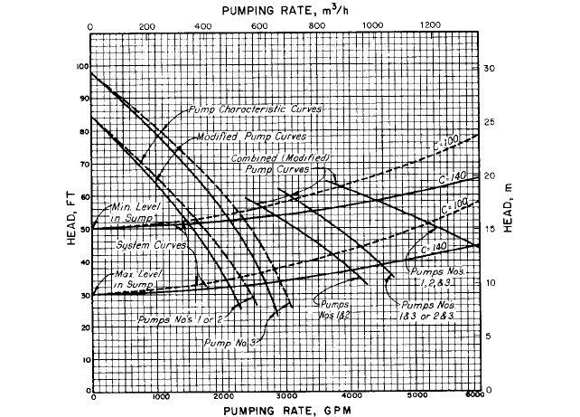
mined by adding the capacity for points of equal head from the modified curve. Figure 12
shows a typical set of system curves, together with representative individual pump charac-
teristic curves,modified pump curves, and combined modified curves for multiple-pump oper-
ation. Intersection of the modified individual and combined pump curves with the system
curves shows total discharge capacity for each of the several possible pumping combinations.
A typical set of system curves consists of two curves with a Williams-Hazen coefficient of C
100 (one for maximum and one for minimum static head) and two curves with a Williams-
Hazen coefficient of C 140 (for maximum and minimum static head). These coefficients rep-
resent the extremes normally found in sewage applications.
Pumps should be selected so the total required capacity of the installation can be deliv-
ered with maximum water level in the wet well and maximum friction in the discharge
line. Pump efficiency should be maximum at average operating conditions. In the case of
Figure 12, assuming that the total capacity of the installation is to be obtained by operat-
ing pumps 1, 2, and 3 in parallel, the total head required at the discharge header would be
approximately 51 ft (15.5 m). Projecting this point horizontally to the individual modified
pump curves and thence vertically to the pump characteristic curves, the required head for
pumps 1 and 2 should be 54 ft (16.5 m) and for pump 3 approximately 57 ft (17.4 m). The
difference between the head obtained from the pump characteristic curve and the modified
curve is the head loss in the suction and discharge piping for the individual pumping units.
Figure 12 also shows the minimum head at which each pump has to operate, approxi-
mately 39 ft (11.9 m) for pumps 1 and 2, and about 42 ft (12.8 m) for pump 3. These mini-
mum heads are important and should be made known to the pump manufacturer because
they will usually determine the maximum brake power required to drive the pump and
the maximum speed at which the pump may operate without cavitation.
PUMP DRIVERS______________________________________________________
In the majority of cases, pumps are driven by electric motors. Sometimes, however, they
are driven by gasoline, gas, or diesel units where firm power is not available or where
pumping is required only at infrequent intervals. Variable-speed drivers are used exten-
sively in sewage applications. These units generally consist of variable-speed motors or
constant-speed motors with adjustable slip couplings of either the eddy-current or the
fluid coupling type. Selection of the type of variable-speed driver to be used is usually
based on space considerations, initial cost, operating cost over the expected life of the
equipment, and customer preference. Emphasis is increasingly being placed on operating
cost over the expected life due to government and environment requirements. See Section
6.2 for these and other types of speed-varying devices.
9.40 CHAPTER NINE
FIGURE 12 Typical head-capacity curves
Variable-speed drivers are particularly appropriate for raw sewage installations that
discharge to a treatment plant. Use of this equipment allows the treatment facilities to
operate continuously instead of intermittently surging the plant at incremental pumping
rates.Variable-speed drivers are used to pump settled sewage and biological sludge where
intermittent surging would adversely affect the process. Also, sludge pumps used to feed
dewatering equipment are often equipped with variable-speed drives because it is neces-
sary to vary the rate of discharge with the dewatering characteristics of the sludge.
For dry pit applications, the choice between horizontal- and vertical-drive motors
depends considerably upon the station arrangement and available space. Horizontal
motors are usually preferred, provided there is space and no potential flooding problem.
Horizontal pumps are more easily maintained, and they are generally less expensive in
first cost. Vertical drivers are generally used, however, for the pumping of raw sewage
because of their smaller space requirements.Also, vertical units are advantageous in that
the motor is located higher and is less susceptible to flooding.
In vertical dry-pit installations, intermediate shafting is normally preferred. This
allows the drivers to be located above a potential flood level in the station. However, the
use of intermediate shafting can become quite expensive in terms of initial installation
costs and maintenance costs. Additionally, they may be prone to vibration problems if
proper precautions are not taken in the design of the station. Vertical drive motor can also
be mounted directly above a pump without the use of intermediate shafting. In doing so,
it is connected to the pump by means of a suitable coupling.A separate support or bracing
of the motor may also be required to provide for adequate installed stiffness.
PUMP CONTROLS____________________________________________________
Some means of controlling pump operation is required at most pumping installations.This
is usually done from either wet-well level or flow.