Pump Handbook by Igor J. Karassik, Joseph P. Messina, Paul Cooper, Charles C. Heald - 3rd edition
Подождите немного. Документ загружается.

9.52 CHAPTER NINE
Total Suction Head The practice for propeller pump installations is to dimension the sta-
tion sump or sump bays in accordance with Hydraulic Institute standards and to make
the distance between the sump floor and the lip of the suction bowl conform to the stan-
dards or the recommendations of the pump manufacturer. The approach and entrance
velocities resulting therefrom are small enough to be disregarded when calculating total
suction head. Total suction head in vertical propeller pump installations is the height from
the centerline or eye of the propeller to the water surface in the sump. For drainage instal-
lations using vertical propeller pumps, a total suction head of zero is not uncommon. In
submerged horizontal propeller pump installations, total suction head is the height from
the centerline of the propeller shaft to the water surface in the sump, and the minimum
value should be not less than 1.2D, where D represents the diameter of the propeller.
Volute pumps equipped with a formed suction or suction piping may operate with
either a suction lift or a suction head, depending on the suction water level. In either case,
all the losses between the entrance and the eye of the impeller should be included in any
calculation. Approach velocity is not a consideration in these installations, but entrance
losses are.
TOTAL SUCTION LIFT Approach and entrance velocities can be disregarded in suction lift
installations by proper dimensioning of the station sump or sump bays and by proper set-
ting of the suction bell. The sump or sump bay dimensions used, as in suction head instal-
lations, should conform to the Hydraulic Institute standards or to the recommendations
of the pump manufacturer. The suction bell for both horizontal propeller pump and ver-
tical volute pump installations should be set with the lip located approximately 0.5D
above the sump floor. For horizontal propeller pump installations, the minimum submer-
gence of the suction bell should be approximately 0.25D, where D is the diameter of the
suction pipe; for volute pump installations it should be 1.5D, where D is the diameter of
the suction bell. In determining the total suction lift for these installations, it is assumed
that the suction piping is a part of the pump and that the approach and entrance veloci-
ties can be disregarded. Total suction lift therefore is the height from the water surface
in the sump to the centerline of the propeller shaft or to the eye of the impeller.
Setting The setting of the pump or the locating of the centerline or eye of the propeller
or impeller with respect to the water surface should be given careful consideration when
selecting the pump to be used. Some installations offer few if any problems in this regard,
whereas in others setting may have a considerable effect on the size and number of pumps
selected.
TURBINE PUMPS
Drawdown is a consideration in any well installation. In setting the pump
to prevent cavitation, sufficient NPSH at the eye of the first-stage impeller and/or suffi-
cient depth over the suction bell lip or tailpipe to prevent vortexing should be maintained
when maximum draw-down is being experienced.
VOLUTE PUMPS Volute pumps may operate with either a suction head or a suction lift. If
with a suction lift and of the horizontal type, the pump should be set above the maximum
anticipated elevation of the suction water source in order to avoid inundation. As prim-
ing will be necessary when starting, a suction lift would be considered a satisfactory
arrangement when long periods of continuous operation are anticipated.
Suction head installation is the preferred practice (because priming is unnecessary)
and should be used whenever conditions permit. In drainage work, vertical volute pumps
are used for pumping small amounts of rainfall runoff and seepage flows.These pumps are
usually located in a dry sump adjacent to the storm water pump sump, with motors and
valve operators located on the operating floor above. The submergence of these pumps
should be such that when discharging at maximum capacity, the total suction head is zero
or above. In many instances, water surface fluctuations of just a few feet occur. When small
volumes are involved, a cycling operation occurs. For this type of operation, the pumps are
usually started at the maximum water level and stopped at the minimum level.
9.3 DRAINAGE AND IRRIGATION 9.53
PROPELLER PUMPS Sufficient water depth does not always exist or cannot always be pro-
vided to give the submergence needed to permit the smallest and perhaps the most effi-
cient pump to be used. Excavation is one answer. However, depending on the soil type, the
location of the installation, the kind of construction used, the silt-carrying characteristics
of the stream, and the frequency of operation, excavation may be an operational and main-
tenance headache and is impractical when sumps are to be made self-draining. Another
alternative
—
and the one most frequently used in drainage work
—
is to set the centerline
or eye of the propeller at or slightly below the minimum sump elevation and select a pump
that will operate at this setting with little or no cavitation damage. This means that a
larger pump operating at a lower speed should be used.
PRIME MOVERS The prime movers used in drainage and irrigation installations are elec-
tric motors and diesel and gas engines.The one to be used in any particular situation must
be determined before the pump can be selected.
Electric motors are the most economical installations; they should be used when a reli-
able source of electric power is available and when the cost of bringing it into the pumping
station is not unreasonable. A reliable source of electric power is a source that historically
has not suffered outages under the climatic conditions that will prevail during the time the
pumps will be required to operate.Two feeders of separate origins and not subject to simul-
taneous outages are sometimes provided to ensure the reliability needed for drainage
installations. Such an arrangement has been satisfactorily employed in urban areas but
would not be a practical solution in remote areas not yet electrified. The cost of construct-
ing and maintaining even one transmission line in such an area could be prohibitive.
The motors in all but the largest installations should be of the squirrel-cage induction
type. In those installations where the motor rating is numerically larger than the speed,
the type of motor used should be the one having the lowest overall first cost. It may be
either a squirrel-cage induction or a synchronous motor.
All motors should be full-voltage starting except in those instances where the local
power company indicates that reduced-voltage starting is necessary. For unattended oper-
ation and for drainage stations pumping seepage or pumping from a sewer system where
frequent cycling is usually necessary, control devices set to start and stop the motors auto-
matically at predetermined sump or discharge pool levels should be provided. In drainage
pumping stations not subject to a cycling operation, motors are started manually by the
operator and stopped automatically by a control device.
Engines are used to drive pumps when it is not feasible to use electric motors.They are
more expensive than motors but reliable if properly maintained and serviced. They are
also variable-speed drives that should be operated at constant speed whenever possible.
The requirements of most installations can be met with constant-speed operation. How-
ever, for those that cannot, the number of speeds used should be held to a minimum.
Engines should not be cycled on and off but should be operated on a continuous basis.
For those installations where the inflow is not sufficient, continuous operation can be
obtained by returning a part of the pumped discharge back to the sump. This is accom-
plished by connecting the pump discharge line and the sump with a valved line.
Gas engines are seldom used, but their use should be considered when the installation
is close to a natural gas main.
Right-angle reduction gears are used to transmit the power from the engine to the
pump shaft of vertical propeller pumps. For horizontal pump installations where the
engine shaft parallels the pump shaft but is at a different elevation and off to one side,
silent chain drives are used. For other horizontal installations, parallel-shaft gear units
may be used. A service of 1.50 should be used when determining the equivalent power of
these units. Right-angle units should be of the hollow-shaft type only if vertical adjust-
ment of the pump impeller is required.
Adequate fuel storage in addition to the day tanks should be provided. Storage facili-
ties should be sufficient to provide fuel at the maximum rate of consumption for a period
of 48 hours or less, as demanded by the anticipated pumping requirements. Larger fuel
storage installations may be needed if replenishment supplies are not readily available.
The design of the facilities should be in accordance with the standards of the National
Board of Fire Underwriters and local agencies having jurisdiction.
9.54 CHAPTER NINE
PUMPING STATION ___________________________________________________
Sump
The sump is perhaps the most important element in the structure of the pump-
ing station. Unless it is properly located, designed, and sized, the flow conditions within
could have an adverse effect on the operation of the pump. There are many variations in
sump arrangements that are acceptable; however, best results are obtained when the
sumps or sump bays are oriented parallel to the line of flow. Flows approaching from an
angle create dead spots and high local velocities, which result in the formation of vortices,
nonuniform entrance velocities, and an increase in entrance losses. The flow to any pump
should not be required to pass another pump before reaching the pump it is meant for.
When sumps or sump bays are normal to the direction of flow, such as in sewer systems,
the distance between the sump or sump bay entrance and the pump must be sufficient for
the flow to straighten itself out before reaching the pump. For additional information rel-
ative to sump design and sizing, refer to Chapter 10. If the installation is large enough to
warrant it, modeling of the sump to permit the best design to be determined is advocated.
Sumps in drainage installations pumping storm water should be either located above
normal water levels, in which case they would be self-draining, or isolated from normal
flows by gates. In small installations, motorized pressure-seating gates should be used; in
large installations, roller gates raised and lowered with a crane or by some other suitable
system should be used. These gates should be sized so the velocity through them will not
exceed 5 ft/s (1.5 m/s) for any condition of flow. One gate should be located directly oppo-
site each pump when all pumps are installed in a common sump or should be located at
the entrance to each sump bay when pumps are separated.
Frequent cycling of pumps is encountered in installations that pump from sewer sys-
tems and that pump seepage. In such installations, the sump should be sized so the vol-
ume stored in it and in the ponding area or the sewer lines, as the case may be, within the
limits of the operating range, will be sufficient to prevent the starting of the pumps more
often than once every four minutes.
Superstructure A superstructure is provided on practically all drainage pumping sta-
tions but not on all irrigation pumping stations. The type of superstructure provided
should be consistent with the surrounding area and should have a minimum number of
windows and openings. In rural areas, corrugated sheet metal structures, which are inex-
pensive, have been used extensively. These provide adequate protection from the elements
and from vandalism. To eliminate the need for an indoor crane, hatches in the roof over
each pump can be provided to permit a truck crane to remove motors and pumps as a unit.
For engine-driven pumps and larger pump installations, indoor cranes of the appropriate
size and type should be provided for installation, removal, and maintenance.
Corrosion The corrosion of electrical and mechanical equipment in housed and
unhoused stations can be controlled by painting exterior surfaces with a good paint and by
installing strip heaters in all electrical enclosures. In large housed installations, heating of
the operating room area in addition to the use of strip heaters should be considered. All
equipment below the operating room floor level should be coated with a paint that is suit-
able for the exposure. In dry sump stations, enamels should be satisfactory. In wet sumps
that are kept dry during inoperative periods, cold-applied coal tar enamel, which is easily
repaired, is preferred. In installations where the equipment is continuously immersed, coal
tar epoxy paint or vinyl paint should be used. If the water is extremely corrosive, consid-
eration should be given to mounting galvanic anodes on the pumps in addition to painting.
FURTHER READING __________________________________________________
Department of the Army, Office of the Chief of Engineers. “Interior Drainage of Leveed
Urban Areas: Hydrology.” EM 1110-2-1410, Washington, DC, 1965.
Department of the Army, Office of the Chief of Engineers. “General Principles of Pumping
Station Design and Layout.” EM 1110-2-8102, Washington, DC, 1962.
9.3 DRAINAGE AND IRRIGATION 9.55
Department of the Army, Office of the Chief of Engineers. “Mechanical and Electrical
Design of Pumping Stations.” EM 11102-3105, Washington, DC, 1962.
Hicks, T. G. Pump Selection and Application. McGraw-Hill, New York, 1957.
Houk, I. E. Irrigation Engineering. Wiley, New York, 1951.
Hydraulic Institute ANSI/HI 2000 Edition Pump Standards, Hydraulic Institute, Parsip-
pany, NJ, www.pumps.org.
Israelson, 0. W. Irrigation Principles and Practices, 2d ed., Wiley, New York, 1950.
U.S. Department of the Interior, Bureau of Reclamation. Turbines and Pumps, Design
Standard 6. Denver, CO, 1960.

MARIO DI MASI
RUDOLPH KAWOHL
9.57
SECTION 9.4
FIRE PUMPS
Compelling reasons dictate the installation of fire protection systems driven by stationary
fire pumps. Foremost among these reasons is protection
—
protection of lives, of equipment,
possessions, and inventories, and of major assets, such as hospitals, hotels, office and res-
idential buildings, and warehouses. There are two additional, less obvious but equally com-
pelling, reasons: the reduction of costs and the protection of income-generating operations.
Costs are reduced in a simple manner. Over the projected life of a facility, the total of con-
struction costs plus fire protection equipment costs plus fire insurance costs is lower than
the total of construction costs plus fire insurance costs without fire protection equipment.
FIRE PROTECTION SYSTEMS __________________________________________
Protection may be provided by a combination of several complementary means, acting at
various levels:
• First by a simple fire detection system activating an alarm
• On the second level, the detection and warning system is combined with a first degree
of fire fighting; for example, with a sprinkler installation, the role of which is to extin-
guish the fire at the beginning or, at least to limit its extension so as to permit inter-
vention with additional equipment
• The third level is a combination of detection, warning, sprinkler and extinguishing
systems (water, inert gases, foam)
The degree of protection is obviously a function of risk. Whereas a fire in a single-
family-dwelling may be warned by phone and then efficiently contained by means of fire
hydrants or fire fighting trucks, the risk of fire in a chemical plant requires a completely
9.58 CHAPTER NINE
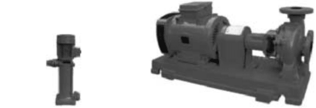
FIGURE 1 Jockey pump (Flowserve
Corporation)
FIGURE 2 First intervention fire pump (Flowserve
Corporation)
different approach. The rules for adequate protection vary from one country to another.
There are, for instance, well known pamphlets published by the U.S. National Fire Pro-
tection Association (NFPA). In Europe, various national rules exist, based on the recom-
mendations of the European Committee of Insurances, such as those of APSAD in France
(Assemblée Plénière des Sociétés d’Assurances Dommages), V d S in Germany (Verband
der Sachversicherer e;v), and LPC in the United Kingdom (Loss Prevention Council).
FIRE PUMP CRITERIA_________________________________________________
The most common liquid available for fire protection and fire fighting continues to be
water. The efficiency of a fire fighting installation depends to a great extent on a depend-
able water supply, which will supply the required flow at the required pressure and be con-
tinuously available during the time necessary to extinguish the particular type of fire in
question.
The needs for fire fighting liquid vary considerably with the degree of danger involved.
When these needs cannot be satisfied from local water sources, such as public water net-
works, high level reservoirs, or pressurized water tanks, pumping stations need to be
designed and situated (located) to address the types of fire possible and the national codes
and standards that exist in a particular country or geographical area.
A typical fire fighting station may be composed of the following:
• A jockey pump (Figure 1) that maintains the desired system pressure within the fire
fighting system. Typical performance for a jockey pump is 10 gpm (38 l/min) at heads
up to 300 ft (92 m).
• A first intervention fire fighting pump (Figure 2) capable of feeding a limited number
(up to 5) of sprinklers. This pump is typically driven by an electrical motor and is fed
from a reservoir capable of supplying at least one hour of liquid flow without interrup-
tion at required flow and pressure. Records indicate that as many as 95% of all fires are
extinguished by this first intervention pump. Typical performance for a first interven-
tion pump is 250 gpm (950 l/min) at a head of 200 ft (60 m).
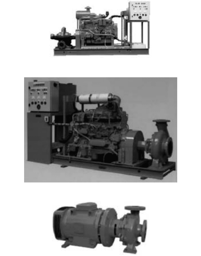
• An emergency fire fighting pump, capable of feeding all available sprinklers, and other
supplementary fire fighting equipment, such as deluge installations and fire-hose noz-
zles. This pump is typically driven by a diesel engine and supplied with fire fighting
water from a (practically) inexhaustible source. The emergency fire fighting pump stan-
dard in North America is a split case pump (Figure 3), whereas the European standard
is an end suction pump (Figure 4). In each case, typical pump performance is from 500
to 5000 gpm (100 to 1200 m
3
/h) at a head of 260 ft (80 m).
• High-rise buildings, protected by sprinklers or standpipes and hose systems, require an
overpressure pump. This pump is generally a close coupled end suction pump (Figure
9.4 FIRE PUMPS 9.59
FIGURE 3 Split case fire pump (Flowserve Corporation)
FIGURE 4 End suction fire pump (Flowserve Corporation)
FIGURE 5 Close-coupled end suction fire pump (Flowserve Corporation)
5) driven by an electrical motor, with typical performance of 150 gpm (34 m
3
/h) and a
head (according to the building height) of at least 200 ft (60 m), sourced from a public
water network.
Although the various national authorities have different approaches to the details of
fire fighting equipment and arrangement, they nevertheless have a similar basic philoso-
phy. The pumps utilized in fire protection systems are usually classical designs. Specifica-
tions require skillful packaging of the complete fire protection system, including the
pump(s), driver(s), starting and control devices and other accessories.
9.60 CHAPTER NINE
Most European codes give considerable freedom of choice relative to pump type and
design, whereas NFPA 20 (United States) is more restrictive. According to NFPA, the
pumps must be of horizontal end-suction or horizontal split-case design. Single stage close
coupled vertical in-line pumps may be used for limited capacities, but these pump types
may not be used where a static suction lift is required. If the pump must lift water from a
well, panel, river, and so on, NFPA 20 requires the use of vertical pumps installed so the
static water level is never below the bottom impeller.
Very high importance is given in all regulations to permanent availability of fire fight-
ing water. Pumps must always be filled with water and must be ready for starting at any
moment. This requirement is obviously satisfied when NFPA 20 compliance is mandatory.
Although the same approach is preferred in Europe, some European codes nevertheless
allow the use of horizontal pumps with a static suction lift. In such cases, the suction pipe
must be fitted with a foot valve, and the pump set must be equipped with a controlled fill-
ing device.
Some rules common to both North America and Europe are
• The shape of the pump performance curves must conform to precise specifications.
• The design pressure of the pump casings is regulated.
• Hydrostatic tests are required.
• Certified performance test curves are required for most fire pumps.
• Fire fighting pumps must be approved, “de jure” (according to written law or regu-
lations) in North America and in most European countries; “de facto” (according to well-
established practices) in the others.
Stationary fire pumps can be purchased as packaged systems, which saves installa-
tion time and money. Single or multiple units of horizontal or vertical pumps can be pack-
aged, and each packaged unit generally includes the pump(s), driver(s), controller(s),
headers, accessories, and piping mounted on a common base. To the extent possible, all
wiring and piping connections are made and the unit is factory-tested. Installation con-
sists simply of positioning and leveling the package and making external piping and elec-
trical connections.
FIRE PUMP DRIVERS _________________________________________________
The principal objective of a fire pump driver is to provide the pump with motive power
under any circumstances. Usual drivers are electric motors, diesel engines or, to a lesser
extent, steam turbines. Although the reliability of the drivers themselves does not really
pose problems, careful consideration must be given to the dependability of the power sup-
ply for electric motors and turbines, and to the fuel supply for diesel engines. Very com-
plete regulations exist in every country which must be considered.
Electric motors are the most economical driver type when a reliable power source is
available. If this is not the case, power must be supplied by two or more independent
sources, one of which may be an emergency generator set. Another choice might be to use
one motor-driven pump and one diesel engine-driven pump. General guidelines for electric
drives are
• Motor power and speed must be selected in accordance with the pump characteristics.
• Depending upon codes and available current, wound rotor, star delta, wye delta primary
resistance, or part-winding start motors may be used.
Diesel engines are frequently used to drive stationary fire pumps. Equipped with bat-
tery packs and automatic controls, they rival electric motors for reliability and eliminate
concern over the dependability of the source of electric power. In order to guarantee the
fuel supply, the tank must be located above ground at an appropriate height. The prevail-
9.4 FIRE PUMPS 9.61
ing philosophy of a diesel engine driven pump is that “the pump must run” in actual fire
conditions. All engine failures (oil pressure, cooling water temperature, speed) should be
indicated only, and should not stop the engine. The only exception to this is the NFPA 20
requirement that a shut-down occur at an over speed of 120%.
Here are some general guidelines for diesel engines:
• Engine power and speed must be selected in accordance with the pump characteristics
(diesel engines are very sensitive to altitude and ambient temperature).
• All energy sources for engine starting must be doubled: two batteries, or two air con-
tainers, or electrical and manual recharge of the hydraulic starting system, and so on.
• An instrument panel secured to the engine at an appropriate place must include a
tachometer, an hour meter, an oil pressure gage, and a water temperature gage.
Occasionally, a fire pump is driven by a steam turbine. When it is desirable to use
steam as the power source, details of the steam supply and exhaust need to be carefully
planned to ensure that the required level of reliability exists.
FIRE PUMP CONTROLLERS ___________________________________________
Regardless of the type of driver, most fire pumps are started automatically by a pressure
signal from the pump discharge line. Each fire pump must have its own controller, includ-
ing the jockey pump.
Depending upon application requirements, fire pump electric motor controllers must
conform to the appropriate national regulations. Each controller must be arranged to
match the starting characteristics of its motor and must include
• Manual disconnect switch
• Circuit breaker
• Starter without heaters or contactors
• Pressure switch (when NFPA is mandatory)
• Minimum-run timer to prevent motor cycling
The diesel engine controller is arranged to permit either automatic or manual start.
The manual start is required to permit periodic run tests. The power source for the con-
troller and for starting is a dual set of batteries or air containers. The controller is
arranged to show the following engine conditions:
• Low lubrication oil pressure
• High water jacket temperature
• Failure to start automatically
• Shut-down due to overspeed (when NFPA 20 is mandatory)
• Battery and battery charger failure or, when equipped with one, an air system failure
The engine controller must also provide a means of relaying the following information
to remote indicators:
• Engine running
• Engine switch off or manual position
• Trouble signal (activated by one or any combination of the engine or controller signals
described above)
Approval of the control system for all pumps, except the jockey pump, is required in
nearly all national codes.
9.62 CHAPTER NINE
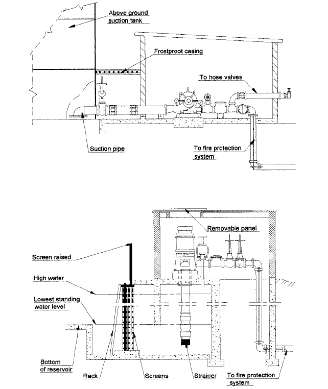
FIGURE 6 Typical installation for horizontal fire pumps
FIGURE 7 Typical installation for vertical fire pumps
GENERAL ENGINEERING PROCEDURE FOR FIRE PROTECTION SYSTEMS ___
As described earlier, fire protection systems can vary greatly depending on the type and
significance of the fire risk, the site conditions and, finally, the various national regulations
in force in the given country. Outlined below are engineering guidelines for stationary
installations using water as protection agent. Figures 6 and 7 show typical installations
for horizontal and vertical fire pumps.
Here are some project basics to keep in mind:
1. Refer to an insurance expert, or to a specialist of a certification board, to confirm that
water may be used for the risks of concerned and to determine which kind of spray
system is recommended: sprinklers, water jets, deluge installations, and so on.