Pump Handbook by Igor J. Karassik, Joseph P. Messina, Paul Cooper, Charles C. Heald - 3rd edition
Подождите немного. Документ загружается.

9.5 STEAM POWER PLANTS 9.93
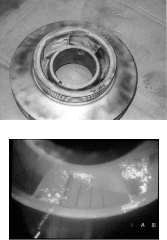
FIGURE 23 Impeller inlet vane cavitation erosion damage (Flowserve Corporation)
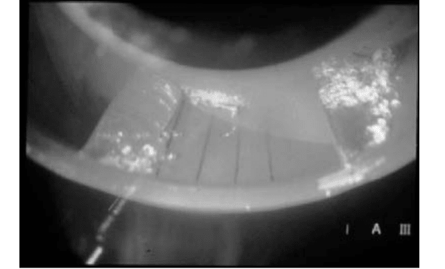
FIGURE 24 Cavitation vapor bubbles on suction surface of the impeller inlet vane (Flowserve Corporation)
vapor bubbles. Cavitation forms around an impeller blade because of local static pressure
falling below the vapor pressure of the liquid being pumped. The vapor cavity shown in
Figure 24 is an example of this phenomenon.
9.94 CHAPTER NINE
FIGURE 25 Operation at same flow as Figure 24, improved inlet vane shape—dramatic vapor bubble reduction
(Flowserve Corporation)
With decreasing flow rates (due to operating at off-design conditions), the fluid
approaches the impeller blade with larger and larger angles of incidence altering the
velocity and pressure fields inside the impeller.
Pumps that are cycled between minimum-flow and flows in excess of the best efficiency
point (BEP) create conditions at the impeller in excess of what “fixed geometry” machines
can effectively tolerate. Impeller geometry has been shown to influence the degree and
severity of cavitation problems experienced with high-energy pumps.
Through the 1980s, attempts were made to pursue “non-traditional” designs of impeller
blading. These efforts took the form of profiling the inlet blade in a way that rapidly
increased and then decreased the blade thickness.
A new impeller blade design approach, referred to as a “biased-wedge” design, has been
found to provide a manufacturable configuration that enables cavitation bubble-free oper-
ation over a wide fluid flow range. This design approach is a result of extensive flow visu-
alization test work and computational fluid flow analysis of many impeller geometries. It
successfully advances the performance of high-energy pump suction stages to levels not
achievable with conventional designs. Dramatic reduction in cavitation activity on the
impeller was recorded as seen in the photo (Figure 25) of the suction surface of the final
impeller taken at identical positions in the suction inlet and at the same operating condi-
tions (baseload and minimum flow) as Figure 24. The inlet vane air foil shape has proven
successful in facilitating feed pump flow rangeability.
Fundamentals for Successful Operating Life
—
Efficiency/Reliability Best practices
for extended successful operating life of pumps are outlined in Chapter 12. Essential fun-
damentals to emphasize for boiler feed pumps are proper pump warm-up, standby warm-
ing, and shaft (fixed bushing) seal drain temperature control. These characteristics have
become more critical as central station plants are cycled and large feed pumps are oper-
ated with varying loads and in standby modes. Current designs of multistage pumps (Fig-
ure 17) installed in combined cycle plants are less sensitive to thermal transients and wide
swings in load (pump flow).
Pre-warming of the pump and maintaining warm-up flow to an idle pump to assure
dimensional thermal uniformity is essential to maintenance of internal clearances, pump
efficiency, and long life. This process is critical for multistage pumps to minimize thermal
9.5 STEAM POWER PLANTS 9.95
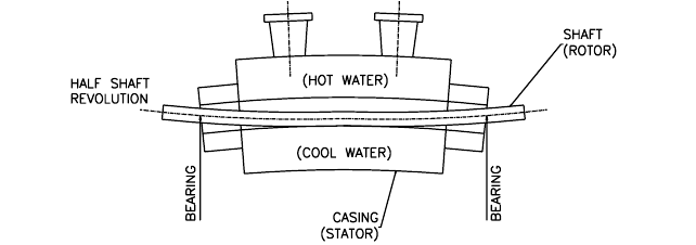
FIGURE 26 Thermal distortion of feed pump casing and shaft, due to improper warm-up and thermal
stratification
stratification within the pump. The distortion, including shaft bowing (Figure 26), will
cause the following potential failure modes:
1. Flashing
2. Internal rubbing
3. Increased wear ring clearances
4. Pump seizure
5. Worn seal bushing clearance and excessive leakage
6. Loss of pump performance and efficiency
7. High pump vibration
8. Worn bearings/bearing clearances
Installation features and operating practices that extend pump life, efficiency, and reli-
ability are
1. Proper pump insulation (Figure 27) at the casing and discharge head
2. Warm-up orifice, piped around the discharge check valve. Preference is to inject warm-
up flow to the bottom of the pump casing to minimize short-circuiting of the hot feed-
water and potential thermal stratification within the casing.
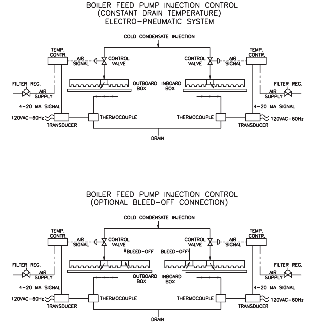
3. Maintaining shaft seal leakage drain temperature (Figure 28) between 150 and 170°F
(65 and 77°C); utilize an electro-pneumatic temperature control system.
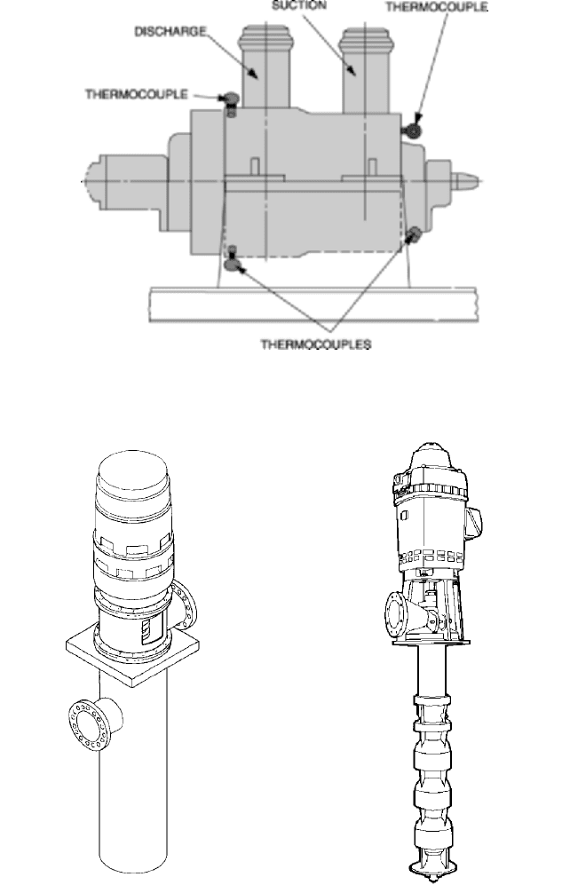
4. Installation of thermocouples or other temperature-detecting instruments (Figure 29)
in the pump casing and discharge head to confirm temperature differences within
50°F (28°C) across the pump and relative to the feedwater temperature.
5. Assurance of proper functioning of the pump casing “pin” and “key” block to allow uni-
form thermal growth. Confirm that the hold-down bolts for the outboard casing feet
are not over-torqued, preventing uniform axial thermal growth as the pump is
heated.
6. Assurance of proper location and functioning of critical pipe hangers to minimize pipe
strain on the pump suction and discharge nozzles.
CONDENSATE PUMPS ________________________________________________
Condensate pumps take their suction from the condenser hot well and discharge either to
the deaerating heater in open feedwater systems (refer to Figure 3) or to the suction of the

9.96 CHAPTER NINE
FIGURE 27 Recommended thermal insulation of a boiler feed pump (Flowserve Corporation)
boiler-feed pumps in closed systems (refer to Figure 6). These pumps, therefore, operate
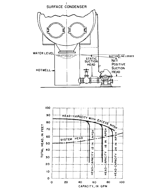
with a very low pressure at their suction. The available NPSH is obtained by the submer-
gence between the water level in the condenser hot well and the centerline of the conden-
sate pump first-stage impeller. Because it is desirable to locate the condenser hot well as
low as possible and avoid the use of a condensate pump pit, the available NPSH is gener-
ally extremely low, on the order of 2 to 4 ft (0.6 to 1.2 m).The exception to this occurs when
vertical-can condensate pumps are used because these can be installed below ground and
higher values of submergence can be obtained. Frictional losses on the suction side must
be kept to an absolute minimum. The piping connection from the hot well to the pump
should therefore be as direct as possible and of ample size and should have a minimum of
fittings.
Because of the low available NPSH, condensate pumps operate at relatively low
speeds, ranging from 1750 rpm in the low range of capacities to 880 rpm.
It is customary to provide a liberal excess capacity margin above the full-load steam
condensing flow to take care of the heater drains that may be dumped into the condenser
hot well if the heater drain pumps are taken out of service for any reason.
Types of Condensate Pumps Both horizontal and vertical condensate pumps are used.
Depending on the total head required, horizontal pumps may be either single-stage or
multistage. Plants constructed in the 1950s and before utilized horizontally split multi-
stage pumps mounted at the lowest plant level, near the bottom of the condenser. As
required condensate flows increased in later years, the common installation incorporated
vertical can-type multistage pumps (Figure 30). Combined cycle plants utilize vertical
turbine-type multistage condensate pumps (Figure 31). The vertical turbine-type pump is
of medium-duty construction and lower in cost than the can-type pump shown in Figure 30.
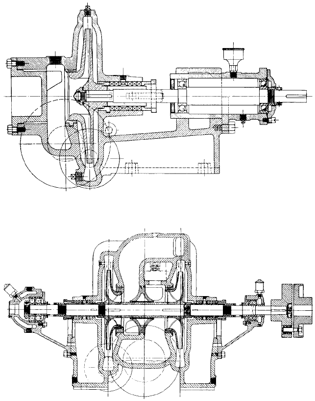
Figure 32 shows a single-suction, single-stage pump with an axially split casing used
for heads up to about 100 ft (30 m). It is designed to have discharge pressure on the stuff-
ing box. The suction opening in the lower half of the casing keeps the suction line at floor
level. An oversize vent at the highest point of the suction chamber permits the escape of
all entrained vapors, which will be vented back to the condenser and removed by the air-
removal apparatus.
Multistage pumps are used for higher heads.A two-stage pump is shown in Figure 33,
with the impellers facing in opposite directions for axial balance. By turning the impeller
9.5 STEAM POWER PLANTS 9.97
FIGURE 28 Boiler feed pump shaft seal injection/leakage control system; electro-pneumatic control of constant
drain temperature
suctions toward the center, both boxes are kept under positive pressure to prevent leak-
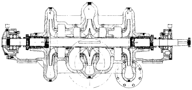
age of air into the pump. For higher heads and larger capacities, a three-stage pump, as
in Figure 34, may be used. The first-stage impeller is of the double-suction type and is
located centrally in the pump. The remaining impellers are of the single-suction type and
are also arranged so both stuffing boxes are under pressure.Two liberal vents connecting
with the suction volute on each side of the first-stage double-suction impeller permit the
escape of vapor.
Current plant construction utilizes vertical can-type condensate pumps (Figures 30
and 31). The chief advantage of these pumps is that ample submergence can be provided
without the necessity of building a dry pit. The first stage of this pump is located at the
bottom of the pumping element, and the available NPSH is the distance between the
water level in the hot well and the centerline of the first-stage impeller.
Condensate pumps are located very close to the condenser hot well, and the suction
piping is generally so short that the frictional losses in this piping are not significant.
However, strainers are occasionally installed in this piping, and a great deal of attention
must be paid to the frictional losses through them and to their frequent cleaning. Cases
have been reported on occasion where the pressure drop across these strainers was suffi-
cient to cause flashing at the suction nozzle of the condensate pumps.
9.98 CHAPTER NINE
FIGURE 29 Feed pump casing and discharge head thermocouple installation, to monitor and control uniform
temperature distribution (Flowserve Corporation)
FIGURE 30 Vertical condensate or heater drain
pump (Flowserve Corporation)
FIGURE 31 Vertical turbine condensate pump
(Flowserve Corporation)
9.5 STEAM POWER PLANTS 9.99
FIGURE 32 Single-stage horizontal condensate pump with axially split casing (Flowserve Corporation)
FIGURE 33 Two-stage horizontal condensate pump with axially split casing (Flowserve Corporation)
The increasing use of full-flow demineralizers in condensate systems and, in the
1960s, the increasing discharge pressures required from the condensate pumps resulted
in the need to split condensate pumping into two parts. The condensate pumps proper
thus develop only a small portion of the total head required. The balance of the required
head was provided by separate condensate booster pumps, which have generally been of
the conventional horizontal, axially split casing type. As larger plants were constructed,
the vertical can-type multistage condensate pump became the standard.
To prevent air leakage at the stuffing boxes, condensate pumps equipped with packing
are always provided with seal cages. The water used for gland sealing must be taken from
9.100 CHAPTER NINE
FIGURE 34 Three-stage horizontal condensate pump with axially split casing (Flowserve Corporation)
the condensate pump discharge manifold beyond all the check valves. Pumps fitted with
mechanical seals also use injection of condensate at a pressure higher than atmospheric
pressure to prevent air from being drawn into the pump and feedwater system across the
seal faces.
Condensate pumps were supplied with cast iron casings and bronze internal parts, but
the emergence of once-through boilers has created the need to eliminate all copper alloys
in the condensate system to avoid deposition of copper on the boiler tubes. Stainless steel-
fitted pumps have become the standard selection for this service.
Condensate Pump Regulation When a condensate pump operates in a closed cycle
ahead of the boiler-feed pump, the two pumps can be considered as a combined unit inso-
far as their head-capacity curve is concerned. Variation in flow is accomplished either by
throttling the boiler-feed pump discharge or by varying the speed of the boiler-feed pump.
In an open feedwater system, several means can be used to vary the condensate pump
capacity with the load:
1. The condensate pump head-capacity curve can be changed by varying the pump speed.
2. Older plant condensate pump head-capacity curves are altered by allowing the pump
to operate in the “break” (Figures 35 and 36).
3. The system-head curve can be artificially changed by throttling the pump discharge
by means of a float control.
4. The pump can operate at the intersection of its head-capacity curve and the normal
system-head curve.The net discharge is controlled by bypassing all excess condensate
back to the condenser hot well.
5. Methods 3 and 4 can be combined so the discharge is throttled back to a prede-
termined minimum, but if the load, and consequently the flow of condensate to the
hot well, are reduced below this minimum, the excess condensate handled by the
pump is bypassed back to the hot well.
The impulse for the controls used in methods 1, 3, and 4 is taken from the deaerator level.
Operating in the break, or “submergence control” as it has often been called, was
applied successfully in many installations before the 1960s. Condensate pumps designed
for submergence control require specialized hydraulic design, correct selection of operat-
ing speeds, and limitation of stage pressures. The pump is operating in the break (that is,
cavitates) at all capacities. However, this cavitation is not severely destructive because the
energy level of the fluid at the point where the vapor bubbles collapse is insufficient to cre-
9.5 STEAM POWER PLANTS 9.101
FIGURE 35 Typical hookup for submergence controlled condensate pump
FIGURE 36 Characteristic of a condensate pump operating on a submergence-controlled system
ate a shock wave of a high enough intensity to inflict physical damage on the pump parts.
If, however, higher values of NPSH were required
—
as for instance with vertical-can con-
densate pumps because of their generally higher operating speed
—
operation in the break
would result in a rapid deterioration of the impellers. It is for this reason that submer-
gence control is not applicable to can-type condensate pumps.
The main advantage of submergence control was its simplicity and the fact that the
power required for any operating condition was less than with any other system. Disad-
vantages occur when the pump is operating at very light loads, however, because the sys-
tem head may require as little as one-half of the total head produced in the normal
head-capacity curve. In this case, the first stage of a two-stage pump produces no head
whatsoever and, if the axial balance was achieved by opposing the two impellers, a definite
thrust is imposed on the thrust bearing, which must be selected with sufficient capacity to
withstand this condition. In addition, no control is available to provide the minimum flow
that may be required through the auxiliaries, such as the ejector condenser.
9.102 CHAPTER NINE
FIGURE 37 Thermostatic control for condensate recirculation
The condensate pump discharge can be throttled by a float control arranged to position
a valve that increases the system-head curve as the level in the hot well is drawn down.This
eliminates the cavitation in the condensate pump, but at the cost of a slight power increase.
Furthermore, the float necessarily operates over a narrow range, and the mechanism tends
to be somewhat sluggish in following rapid load changes, often resulting in capacity and
pressure surges.This transient condition is often the root cause of failed thrust bearings and
axial rotor shifting. Another critical piping arrangement feature is the discharge piping
check valve. The check valve in every condensate pump must be below the condenser
hotwell level to ensure prevention of air entrapment and start-up waterhammer. [Refer to
Section 8.3.]
When condensate delivery is controlled through bypassing, the hot well float controls a
valve in a bypass line connecting the pump discharge back to the hot well. At maximum
condensate flow, the float is at its upper limit with the bypass closed and all the condensate
is delivered to the system. As the condensate flow to the hot well decreases, the hot well
level falls, carrying the float down and opening the bypass. Sluggish float action can create
the same problems of system instability in bypass control as in throttling control, however,
and the power consumption is excessive because the pump always operates at full capacity.
A combination of throttling and bypassing control eliminates the shortcoming of exces-
sive power consumption. The minimum flow at which bypassing begins is selected to pro-
vide sufficient flow through the ejector condenser.
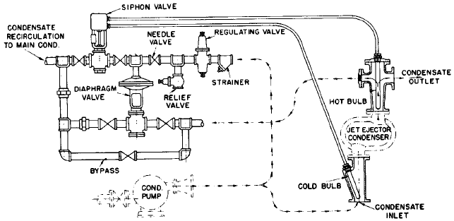
A modification of the bypassing control for minimum flow is illustrated in Figure 37,
which shows a thermostatic control for condensate recirculation.With practically constant
steam flow through the ejector, the rise in condensate temperature between the inlet and
outlet of the ejector condenser is a close indication of condensate flow rate through the
ejector condenser tubes. Therefore an automatic device to regulate the condensate flow
rate can be controlled by this temperature differential. A small pipe is connected from the
condensate outlet on the ejector condenser back into the main condenser shell. An auto-
matic valve is installed in this line and is actuated and controlled by the temperature rise
of the condensate.Whenever the temperature rises to a certain predetermined figure, indi-
cating a low flow of condensate, the automatic valve begins to open, allowing some of the
condensate to return to the condenser and then to the condensate pump, which supplies it
to the ejector at the increased rate. When the temperature rise through the ejector con-
denser is less than the limiting amount, indicating that ample condensate is flowing
through the ejector condenser, the automatic valve remains closed.
As condensate flow design demand increased, the vertical multistage pumps were
installed as two half-capacity pumps. Flow variation is accomplished by operating one or
two pumps and by utilizing the regulating discharge valve.