Pump Handbook by Igor J. Karassik, Joseph P. Messina, Paul Cooper, Charles C. Heald - 3rd edition
Подождите немного. Документ загружается.

9.5 STEAM POWER PLANTS 9.103
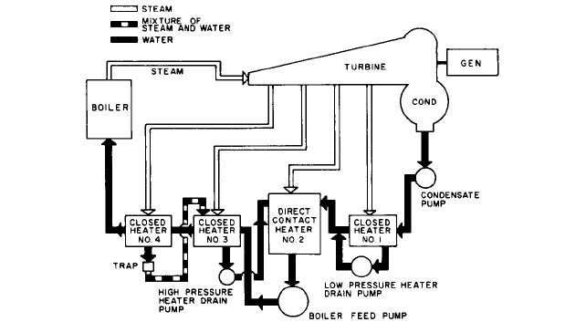
FIGURE 38 Typical arrangement for heater drain pumps
Just as in the case of boiler-feed pumps
—
or, as a matter of fact, of any pumps
—
condensate pumps should not be operated at shutoff or even at certain reduced flows.This
subject is covered in detail in Subsections 2.3.1 and 2.3.4. Emphasis is placed on the impor-
tance of preventing “dead-heading,” where the weaker pump in a two-pump system with
only one minimum flow protection loop is forced to operate at shut-off or zero flow rate.
HEATER DRAIN PUMPS _______________________________________________
Service Conditions
Condensate drains from closed heaters can be flashed to the steam
space of a lower-pressure heater or pumped into the feedwater cycle at some higher-
pressure point. Piping each heater drain to the heater having the next lower pressure is
the simpler mechanical arrangement and requires no power-driven equipment. This “cas-
cading” is accomplished by an appropriate trap in each heater drain. A series of heaters
can thus be drained by cascading from heater to heater in the order of descending pres-
sure, the lowest being drained directly to the condenser.
This arrangement, however, introduces a loss of heat because the heat content of the
drains from the lowest-pressure heater is dissipated in the condenser by transfer to the
circulating water. It is generally the practice, therefore, to cascade only down to the lowest-
pressure heater and pump the drains from that heater back into the feedwater cycle, as
shown in Figure 38. Because the pressure in that heater hot well is low (frequently below
atmospheric even at full load), heater drain pumps on that service are commonly described
as on “low-pressure heater drain service.”
In an open cycle, drains from heaters located beyond the deaerator are cascaded to the
deaerator. Although the deaerator is generally located above the closed heaters, the dif-
ference in pressure is sufficient to overcome both the static and the frictional losses. This
difference in pressure decreases with a reduction in load, however, and at some partial
main turbine load it becomes insufficient to evacuate the heater drains. They must be
switched to a lower-pressure heater or even to the condenser, with a subsequent loss of
heat. To avoid these complications, a “high-pressure heater drain pump” is generally used
to transfer these drains to the deaerator. Actually, this pump has a “reverse” system head
to work against; at full load, the required total head may be negative, whereas at light
loads, the required head is at its maximum.
9.104 CHAPTER NINE
High-pressure drain pumps are subject to more severe conditions than boiler-feed
pumps encounter:
1. Their suction pressure and temperature are higher.
2. The available NPSH is generally extremely limited.
3. They are subject to all the transient conditions to which the feed pump is exposed dur-
ing sudden load fluctuations, and these transients are more severe than those at the
feed pump suction.
Types of Heater Drain Pumps In the past, heater drain pumps were often horizontal,
either single-stage or multistage, depending upon total head requirements. In the single
stage type, end-suction pumps of the heavier “process pump” construction (Figure 43)
were preferred for both low- and high-pressure service. Current construction features the
vertical can-type pump (Figure 30) on heater drain services. As previously described, the
advantages of the vertical can pump are lower first cost and a built-in additional NPSH
because the first-stage impeller is lowered below floor level in the can. Against these
advantages, one must weigh certain shortcomings. A horizontal heater drain pump is
more easily inspected than a can pump. The external grease- or oil-lubricated bearings
of the horizontal pump are less vulnerable to the severe operating conditions during
swinging loads than the water-lubricated internal bearings of the can pump. If vertical
can heater drain pumps have a bearing in the suction bell, consideration must be given
to the fact that the water in the immediate location of that bearing is at near saturated
pressure and temperature conditions (high temperature and low pressure). To keep the
water in the bearing from flashing, additional water should be piped back to the bearing
from a higher stage.
Heater drain pumps should be adequately vented to the steam space of the heater.
Because heater drain pumps and especially those on low-pressure service may operate
with suction pressures below atmospheric, it is necessary to provide a liquid supply to the
seal cages in the stuffing boxes. Low-pressure heater drain pumps use cast iron casings
and bronze fittings if no evidence of corrosion erosion has been uncovered. On high-
pressure services, stainless steel components are generally mandatory and 12% chrome
stainless steel casings are preferred.
CONDENSER CIRCULATING PUMPS ____________________________________
Types of Pumps
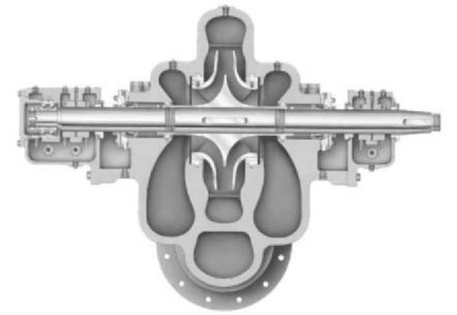
Condenser circulating pumps may be of either horizontal or vertical
construction. For many years, the low-speed, horizontal, double-suction volute centifugal
pump (Figure 39) was the preferred type. This pump has a simple but rugged design that
allows ready access to the interior for examination and rapid dismantling if repairs are
required.
The larger central station and combined cycle power plants have switched to wet-pit
vertical pumps that are either fully or partially submerged in the water pumped. Central
stations also installed vertical dry-pit pumps in the 1950s and 1960s. These dry-pit
designs are large vertical volute casing pumps surrounded by air.
Mechanical Considerations The dry-pit installation was a single-suction, medium-
specific-speed, mixed-flow pump (Subsection 2.2.1, Figure 109). This design combined the
high efficiency and low maintenance of the horizontal double-suction radial-flow cen-
trifugal pump with lower cost and slightly higher rotative speeds.
Because of their suction and discharge nozzle arrangements, these pumps are ideally
suited for vertical mounting in a dry pit, preferably at the lowest water level, so they are
self-priming on starting. They are directly connected to solid-shaft induction or synchro-
nous motors, either close-coupled or with intermediate shafting between the pump and the
motor, which is then mounted well above the pump pit floor.
Like the horizontal double-suction pump, the vertical dry-pit mixed-flow pump is a com-
pact and sturdy piece of equipment. Its rotor is supported by external oil-lubricated bearings
9.5 STEAM POWER PLANTS 9.105
FIGURE 39 Horizontal double suction single stage pump, IDP model LN (Flowserve Corporation)
of optimum design.This construction requires the least attention, for the oil level can be eas-
ily inspected by means of an oil sight glass mounted at the side of the bearing or oil reservoir.
Because the rotor is readily removed through the top of the casing, facilitating main-
tenance and replacement, the pump does not have to be removed from its mounting and
the suction and discharge connections do not have to be broken to make periodic inspec-
tions or repairs.
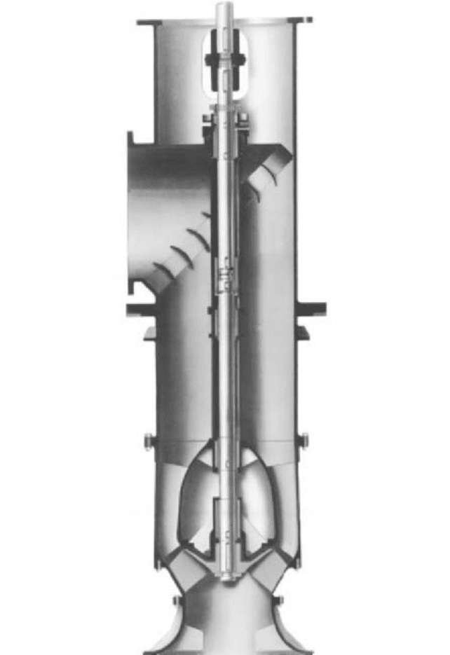
In recent years, power plant designers have shown a preference for the wet-pit column-
type condensate circulating pump. The term wet-pit normally implies a casing diffuser-
type pump, employing a single open vane impeller. The wet-pit pump (Figure 40) employs
a long column pipe that supports the submerged pumping element. It is available with
open main shaft bearings lubricated by the water handled, or with enclosed shafting and
bearings, lubricated by clean, fresh, filtered water from an external source. There is some
danger of contamination of the lubricating water from seepage into the shaft enclosure
tube during shut-downs.
Pulling up the column in a long pump requires special facilities and, in addition, the dis-
charge flange must be disconnected when withdrawing the pump and column from the pit.
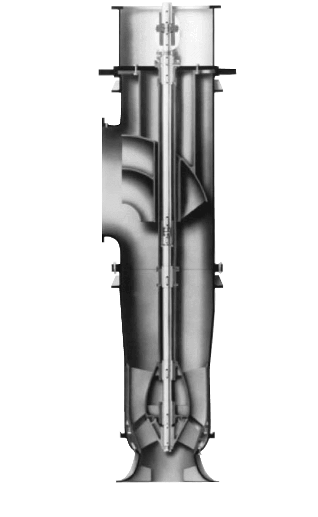
This design has been designated a “non-pull-out” design (Figure 40). To avoid the necessity
of lifting the entire pump when the internal parts require maintenance, some units are built
so the impeller, impeller shroud, casing, and shaft assembly can be removed from the top
without disturbing the column pipe assembly. (The driving motor must be removed.) These
designs are commonly designated “pull-out” designs (Figure 41).
Condenser cooling water is often corrosive. Power plants are often located near salt or
brackish bodies of water. Plants near rivers often encounter water contaminated with high
silt levels.With such waters, selection of materials can be critical to long service life. Mate-
rial selection for sea water applications must also consider the potential for electrolytic
(galvanic) corrosion.
Performance Characteristics Condenser circulating pumps are normally required to
work against low or moderate heads. Extreme care should be exercised in calculating the
system frictional losses, which include losses from friction in the condenser. If more total
9.106 CHAPTER NINE
FIGURE 40 Vertical wet pit circulating water pump (non-pull-out) (Flowserve Corporation)
head is specified than is required, the resulting driver size may be unnecessarily
increased. For instance, an excess of 1 or 2 ft (0.3 or 0.6 m) in an installation requiring
only 20 ft (6 m) of head represents an increase of 5 to 10% in excess power costs.
9.5 STEAM POWER PLANTS 9.107
FIGURE 41 Vertical wet pit circulating water pump (pull-out) (Flowserve Corporation)
9.108 CHAPTER NINE
The range of suction lift for dry-pit pumps must be determined very accurately and
checked with the manufacturer to ensure that cavitation will be avoided in the installa-
tion. Priming facilities must be provided, or the pump must be installed in a dry pit at such
an elevation that the water in the suction channel leading to the pump will be maintained
at the level recommended by the manufacturer. This presents no problem in a wet-pit
installation because the pump column can be made long enough to provide adequate sub-
mergence, even with minimum water levels in the suction well or pit. The dry-pit pump
will generally have 3 to 4% higher efficiency than the wet-pit type and therefore 3 to 4%
lower power consumption. The two types are available for the same specific speed range.
When pumping total head is 25 ft (7.6 m) or less, an axial-flow propeller (approximately
10,000 specific speed in USCS units) can be used in either type of pump.
The low-specific-speed, double-suction pump has a very moderate rise in head with
reducing capacities and a nonoverloading power curve with a reduction in head. The
mixed-flow impeller with a higher specific speed has a steeper head-capacity curve and a
reasonably flat power curve that is also nonoverloading. As the specific speed increases,
the steepness of the head-capacity curve increases and the curvature of the power curve
reverses itself, hitting a maximum at the lowest flow. Finally, the curve of a high-specific-
speed propeller pump has the highest rise in both head-capacity and power-capacity
curves toward zero flow. The head range developed by the mixed-flow pump is ideal for
condenser service; this pump is usually furnished with an enclosed impeller, which pro-
duces a relatively flat head-capacity curve and a flat power characteristic.
Higher head circulating water pumps were developed in the 1970s as cooling towers
were introduced to improve plant efficiency and environmental contamination. The
cooling tower arrangement effectively increased the total system resistance head
requirements.
System Hydraulics The dry-pit pump is not too sensitive to the suction well design
because the inlet piping and the formed design of the suction passages into the pump nor-
mally ensure a uniform flow into the eye of the impeller. On the other hand, the higher-
speed wet-pit pumps are more sensitive to departures from ideal inlet conditions than the
low-speed centrifugal volute pump or the medium-speed mixed-flow pump. A discussion of
the arrangements recommended for wet- and dry-pit pump installations is presented in Sec-
tion 10.1.
Drivers Whether a dry-pit or a wet-pit pump is used, the axial thrust and weight of the
pump rotor are normally carried by a thrust bearing in the motor, and the driver and dri-
ven shafts are connected through a rigid coupling. The higher rotative speeds of the wet-
pit pumps reduce the cost of the electric motors somewhat. This difference may be offset,
however, by the fact that the thrust load of the wet-pit pump is higher than that of the
dry-pit pump.
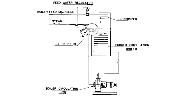
BOILER CIRCULATING PUMPS _________________________________________
The forced circulation, or controlled circulation, boiler requires the use of circulating pumps
that take their suction from a header connected to several downcomers, which originate
from the bottom of the boiler drum and discharge through the various tube circuits operat-
ing in parallel (Figure 42).The circulating pumps therefore must develop a pressure equiv-
alent to the frictional losses through these tube circuits.Thus, in the case of different boilers
operating in pressure ranges from 1800 to 3000 lb/in
2
(124 to 207 bar), the boiler circulat-
ing pump must handle feedwater from 620 to 690°F (326 to 365°C) under a suction pressure
of 1800 to 2900 lb/in
2
(124 to 200 bar). Such a combination of high suction pressure and high
water temperature at saturation imposes very severe conditions on the circulating pump
stuffing boxes, making it necessary to develop special designs for this part of the pump.
The net pressure to be developed by these pumps is relatively low, ranging from 50 to 150
lb/in
2
(3.4 to 10.3 bar). Hence these are single-stage pumps with single-suction impellers and
a single stuffing box.The high boiler pressure imposes an extremely severe axial thrust on the
9.5 STEAM POWER PLANTS 9.109
FIGURE 42 Forced, or controlled, circulation system
pump, placing a load of several tons on the thrust bearing. In many cases, a thrust-relieving
device must be incorporated to permit pump start-up. Two general types of construction are
used for this service: (1) the conventional centrifugal pump with various stuffing box modifi-
cations (Figure 43) and (2) the submersible motor pump of either the wet- or dry-stator type
(Figure 44). In the lower boiler pressure range-up to 500 or 600 lb/in
2
gauge (34 or 41 bar), the
construction shown in Figure 45 may be used.The pump is of the same general type as is used
on high-pressure heater drain service.The packed stuffing box or mechanical seal is preceded
by a pressure-reducing bushing. Feedwater from the boiler-feed pump discharge, at a tem-
perature lower than in the boiler drum and at a pressure somewhat higher than pump inter-
nal pressure, is injected into the middle of this bushing. Part of this injected feedwater
proceeds toward the pump interior, making a barrier against the outflow of high-temperature
water. The rest proceeds outward to a bleed portion of the bushing, from where it is bled to a
lower pressure, often the deaerator. The packing or mechanical seal needs to withstand only
the lower boiler-feed pump temperature and a much lower pressure than boiler pressure.
More sophisticated designs are required for pressures from 1800 to 3000 lb/in
2
gauge
(124 to 207 bar) (Figure 43). The shaft is sealed by two floating ring pressure breakdowns
and a water-jacketed stuffing box. Boiler feedwater is injected at a point between the lower
and upper stacks of floating ring seals at a pressure about 50 lb/in
2
(3.5 bar) above the
pump internal pressure. Here again, part of this injection leaks into the pump interior and
the rest leaks past the upper stack of seals to a region of low pressure in the feed cycle.
Leakage to atmosphere is controlled by the conventional stuffing box located above the
upper stack. The seal injection and leakoff control system is very sensitive to boiler and
feedwater pump transients. Loss of injection results in flashing in the sealing chamber
and failure of the sealing rings. Current technology utilizes a two-stage, high-pressure
mechanical seal. This eliminates the need for a separate seal injection system and seal-
injection booster pump.
The available NPSH may not be sufficient at start-up, when the water in the boiler is
cold and the pressure is low. Therefore certain installations include two-speed motors so a
lower NPSH is required at start-up. There is an added advantage to this arrangement:
under normal operating conditions, the feedwater will heat boiler saturation temperature
and therefore will have a specific gravity of as low as 0.60; at start-up, however, the spe-
cific gravity will be 1.0. The power consumption on cold water would therefore be some
65% higher than in normal operation if the pump operates at the same speed, and a much
larger motor would be required. If a two-speed motor is used, however, the pump is oper-
ated at lower speed when the water is cold, and the motor need be only large enough to
supply the maximum power required under normal operating conditions.

9.110 CHAPTER NINE
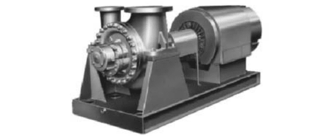
FIGURE 43 Vertical injection-type boiler circulating
pump for high pressures (Flowserve Corporation)
FIGURE 44 Boiler circulating pumps driven by a
wet stator motor (Hayward Tyler)
FIGURE 45 End-suction boiler circulating pump for low-pressure range (Flowserve Corporation)
ASH-HANDLING PUMPS_______________________________________________
Boilers that use solid fossil fuels produce refuse that is generally classified as ash and
includes bottom ash or slag, fly ash, and mill rejects such as pyrites and so on. This refuse
9.5 STEAM POWER PLANTS 9.111
FIGURE 46 Horizontal single stage double suction, high head pump (Flowserve Corporation)
must be removed and disposed of, either by hydraulic or pneumatic conveying. The latter,
of course, does not involve the use of pumps and need not be discussed here.
Fly ash and bottom ash is removed from the boiler system through a series of water
ejectors. Centrifugal pumps provide the water, taken from either the circulating water
pump header or ash-settling pond. These pumps (Figure 46) are subjected to severe duty
as pump flows vary significantly and the pumpage is often contaminated with suspended
silt or fly ash.
Hydraulic conveying is generally restricted to bottom ash and mill rejects. There are a
great number of different systems in use today, and the reader should consult boiler design
and operation literature to become acquainted with this subject. What is common to most
hydraulic conveying systems is that they use centrifugal pumps to handle concentrated
ash slurries that may contain considerable amounts of coarse, heavy pieces of stone, slate,
and iron pyrites. Pumps suitable for this service are described in detail in Subsection
9.16.2.
REFERENCES _______________________________________________________
Liao, C. S., and Leung, P. “Analysis of Feedwater Pump Suction Pressure Decay.” ASME J.
Eng. Power, April 1972, p. 33.
Liao, C. S. “Protection of Boiler Feed Pump Against Transient Suction Pressure Decay.”
ASME J. Eng. Power, July 1974, p. 247.
FURTHER READING __________________________________________________
Karassik, I. J. “Steam Power Plant Clinics.” A series of articles in Combustion Engineering,
1958 through 1976.

SOLUTION CHARACTERISTICS_________________________________________
Chemical industries can be broadly defined as those that make, use, or dispose of chemi-
cals.The pumps used in these industries are different from those used in other industries
primarily in the materials from which they are made.Although cast iron, ductile iron, car-
bon steel, and aluminum- or copper-base alloys will handle a few chemical solutions, most
chemical pumps are made of stainless steel, Hastelloy, the nickel-base alloys, or the more
exotic metals, such as titanium and zirconium. Pumps are also available in carbon, glass,
porcelain, rubber, lead, and whole families of engineering polymers, including the ther-
moplastics, thermosets, epoxies, and fluorocarbons. Each of these materials has been incor-
porated into pump design for just one reason
—
to eliminate or reduce the destructive effect
of the chemical liquid on the pump parts.
Because the type of corrosive liquid to be pumped determines which of these materials
is most suitable, a careful analysis of the chemical solution to be handled is the first step
in selecting the proper materials for pump construction.
Major and Minor Constituents Foremost in importance in a study of the characteris-
tics of any solution are the constituents of the solution. This means not only the major
constituents but the minor ones as well, for in many instances the minor constituents will
be the more important. They can drastically alter corrosion rates, and therefore a full and
detailed analysis is most critical.
Concentration Closely allied to what the constituents are is the concentration of each.
Merely stating “concentrated,” “dilute,” or “trace quantities” is basically meaningless
because of the broad scope of interpretation of these terms. For instance, some interpret
concentrated as meaning any constituent having a concentration of greater than 50% by
weight, whereas others interpret any concentration above 5% in a like manner. Hence it
JOHN R. BIRK
JAMES H. PEACOCK
FREDERIC W. BUSE
9.113
SECTION 9.6
CHEMICAL INDUSTRY