Power electronic handbook
Подождите немного. Документ загружается.

20 Gate Drive Circuitry for Power Converters 551
15V
15V
PWM2
PWM1
M1
T1
M2
M3
M4
R4
D2 R3
R2
R5
R6
Dz4
Dz3
Dz2
Dz1
DC Bus
IGBT1
IGBT2
LOAD
C2
C1
D1 R1
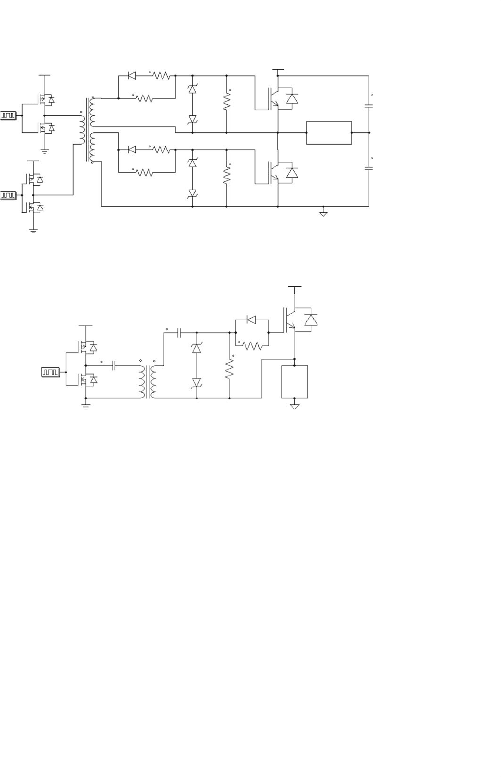
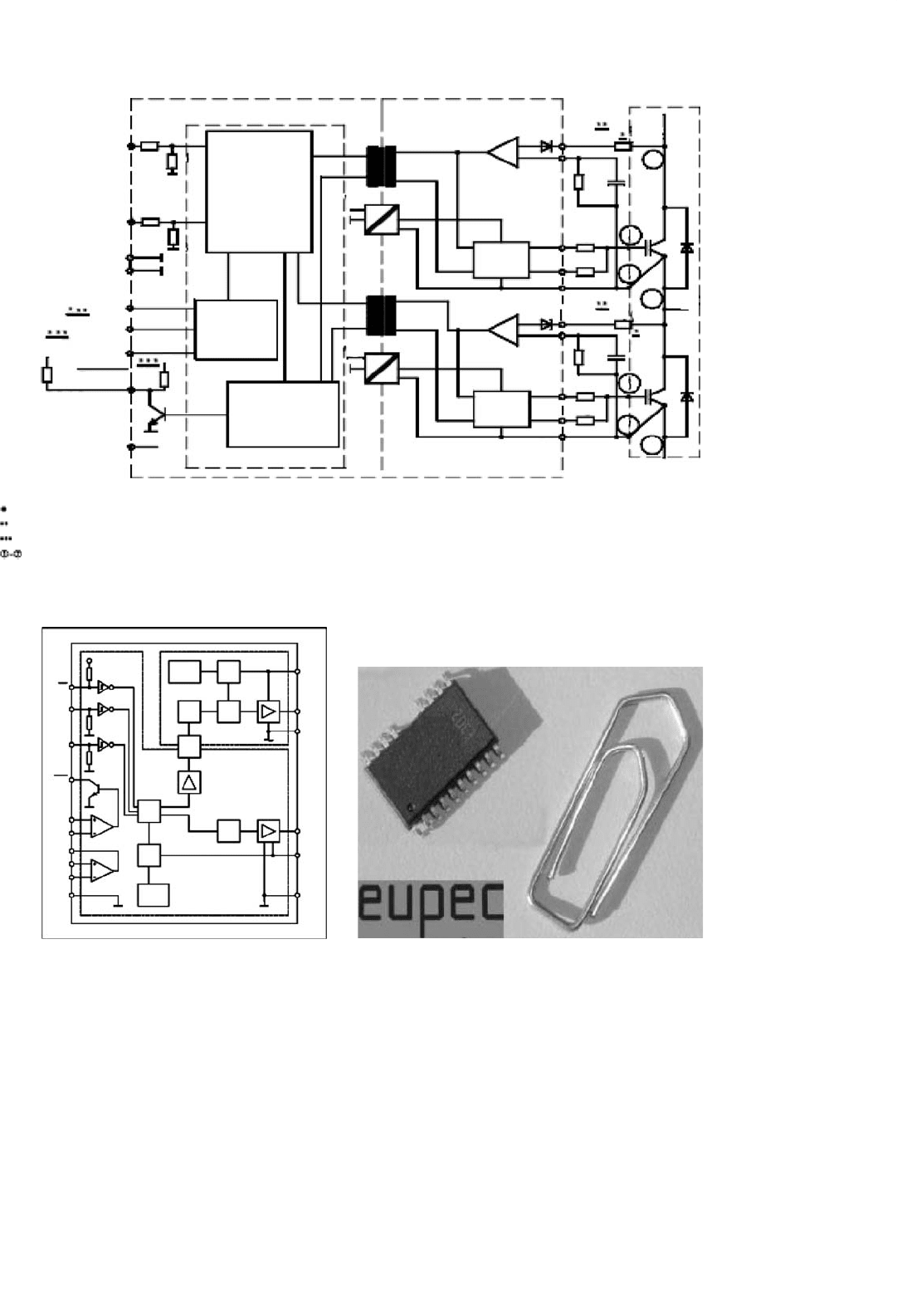
FIGURE 20.14 Transformer coupled gate driver used to supply both the control signal and the gate drive power to the device.
15V
PWM
M1
M2
C1
C2
R2
T1
R1
D1
DC Bus
IGBT1
LOAD
Dz1
Dz2
FIGURE 20.15 Transformer coupled gate driver with a large duty cycle operating range.
purpose as described in Fig. 20.12. The second function
of this passive resistor network, is to dampen ringing
effects. This is caused by the interaction between the
IGBT or power MOSFET gate capacitance, and the gate
drive transformer leakage inductance.
• Transformer Coupled Gate Driver with Large Duty
Cycle Capability
Transformers offer excellent noise immunity and pro-
vide simple and cost-effective gate drive solutions, whilst
maintaining electrical isolation between the control and
gate drive electronics. A drawback however is the limita-
tion the transformer places on the maximum operating
duty cycle. Figure 20.15 offers a simple but effective solu-
tion to the conventional limitations by the introduction
of a DC restorer circuit which is formed by C2, Dz1, and
Dz2. This system allows for removal of any DC infor-
mation via C1, and restores the input waveform applied
with the addition of a negative voltage bias needed for
the IGBT gate drive. A small ferrite transformer core
can be used for a MOSFET gate driver operational to
several hundred kilohertz. This circuit can be redesigned
for bridge topologies, but is also well suited for high volt-
age DC–DC converters requiring a high-side switch. The
effective duty cycle range of this driver is from 5 to 95%.
Operating waveforms are shown in Fig. 20.16.
It should be noted that the gate drive voltage is
clamped at fixed levels regardless of the duty cycle used,
unlike the case in Fig. 20.9. This technique also supplies
both the level shifted signal as well as the gate drive power,
eliminating the need for an additional floating supply.
The transformer turns ratio (T1) can also be adjusted to
allow the circuit in Fig. 20.15 to operate from a 5 V sup-
ply, whilst generating an output voltage swing from +15
to −5 V at the IGBT gate.
•
Transformer Coupled Signal Modulated Gate Driver
The circuit in Fig. 20.17 employs a high-frequency car-
rier signal that is modulated by a lower frequency
control signal (PWM). This is used to generate on/off
switching instants of power IGBT1. By employing a high-
frequency carrier, the transformer size is reduced, and
552 I. Khan
V1
0
V1
–V2
V1
0
V1
–V2
V1
0
V1
–V2
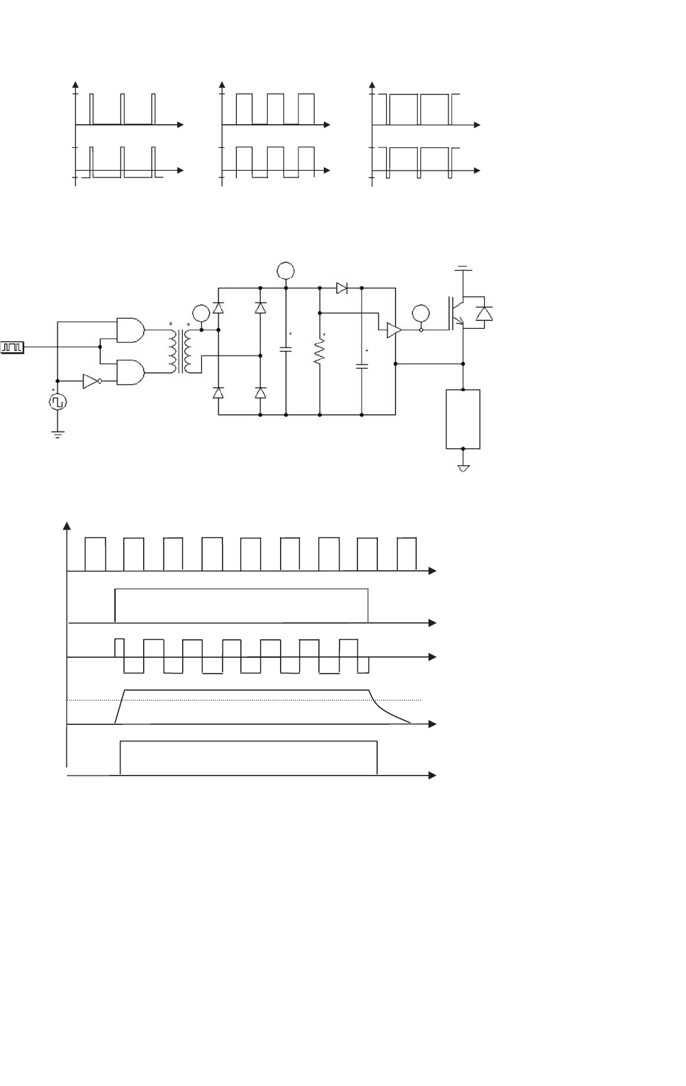
(a) 5% duty cycle (b) 50% duty cycle (c) 95% duty cycle
PWM
Vgate
FIGURE 20.16 Operating waveforms of the transformer coupled gate driver in Fig. 20.15.
U1
D1
C1
C2
R1
U1
D3
D5
D4D2
V
V
V
Vsec
Vout
Vgate
IGBT1
LOAD
DC Bus
T1
U1B
U1A
PWM
VSQ1
FIGURE 20.17 Signal modulated carrier used for level shifting and generation of a floating supply.
V
Sec
V
SQ1
V
PWM
V
Out
V
Gate
t
Vtrigger
FIGURE 20.18 Signal modulated carrier used for level shifting and generation of a floating supply.
by modulating the time in which the carrier operates,
it controls the energy delivered to the gate of the IGBT.
A carrier frequency for VSQ1 should be chosen to be
much higher than the frequency of the PWM control
signal. When the PWM control signal is enabled, the
carrier signal is transformed to the secondary of trans-
former T1, which is rectified and filtered to produce a
DC signal V
out
.
When the PWM control signal goes from the on- to
the off-state, the charge stored in the filter capacitor C1
discharges by a time constant determined by R1. This
is sometimes problematic when fast switching times
are required, especially in inverter bridge configura-
tions. A solution to this problem is to employ an
active driver (U1) on the secondary side of the trans-
former. This will detect the carrier, and switch the IGBT
20 Gate Drive Circuitry for Power Converters 553
R2
20 k
U1B
U1A
+15V
D1
T1
D2
Gate
Drive
cct
D5
D4
1u
C3
D3
V
SV
R1
R3
C2
1u
100
12 k
C1
1n
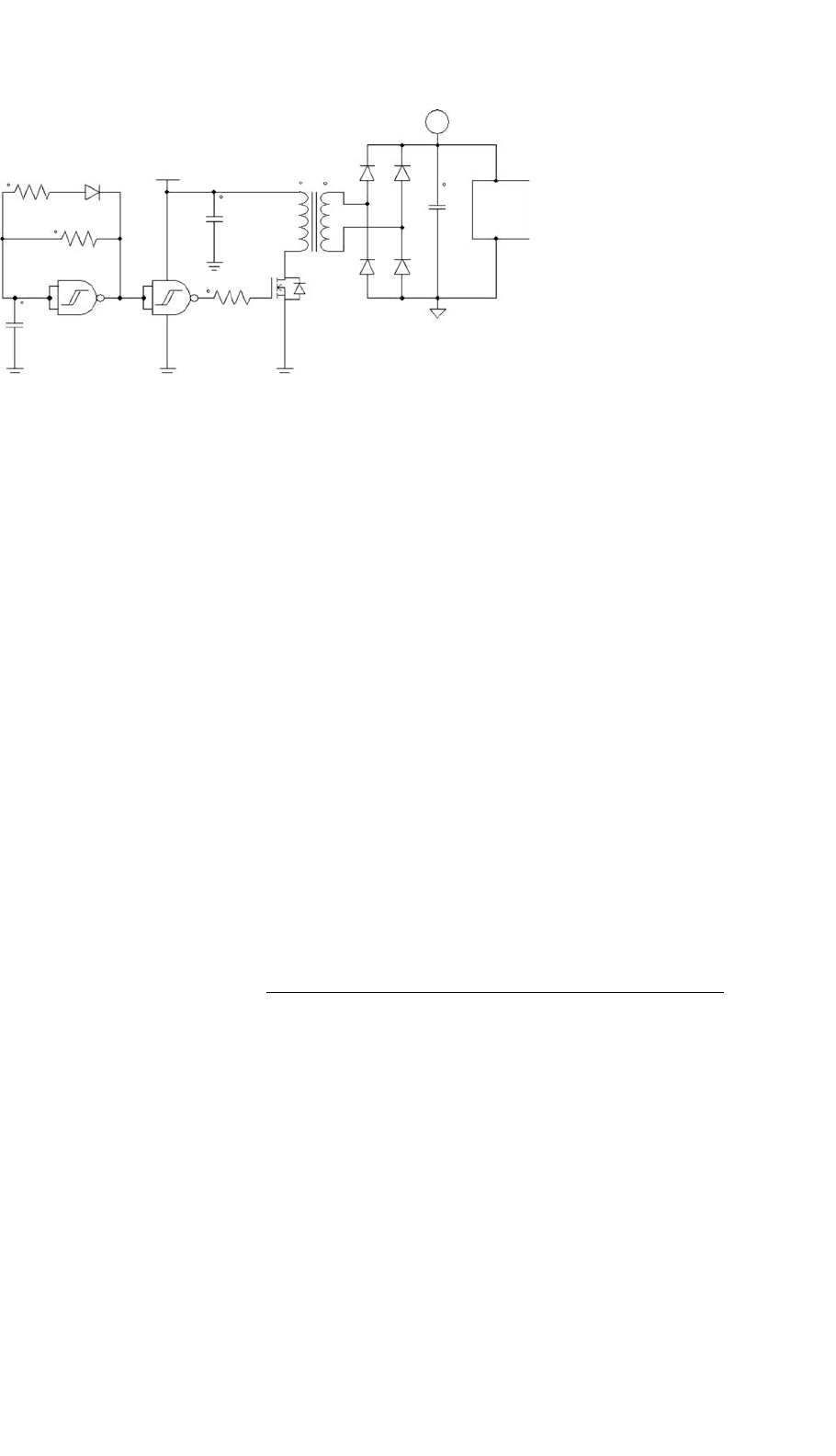
FIGURE 20.19 Low cost high frequency switch-mode floating supply.
gate accordingly. Operating waveforms for this circuit is
shown in Fig. 20.18 [1].
• High Frequency Floating Power Supply
Often gate driver systems require extra electronics which
has to be referenced to the floating switch being driven.
Extra functional electronics often leads to higher power
consumption, resulting in the need for a small low cost
floating power supply as shown Fig. 20.19. The input
section consisting of U1B, forms an oscillator used to
drive a MOSFET at high frequency. This MOSFET drives
a high-frequency transformer, which forms the isolation
medium between the common auxiliary power supply
and the floating secondary circuit. Transformer T1 pro-
duces a secondary output voltage which is rectified to
form a floating DC supply for the associated gate drive
circuitry. These floating power supplies are also avail-
able as monolithic DC–DC converter ICs with isolated
outputs.
20.4.2 Electronic Gate Drivers
These drivers utilize electronics in order to store energy in
capacitors. This is used to produce floating referenced poten-
tials. All circuits are referenced to a common ground potential.
This technique provides a very cost-effective gate driver solu-
tion over the isolated versions, and are becoming increasingly
popular in industries.
•
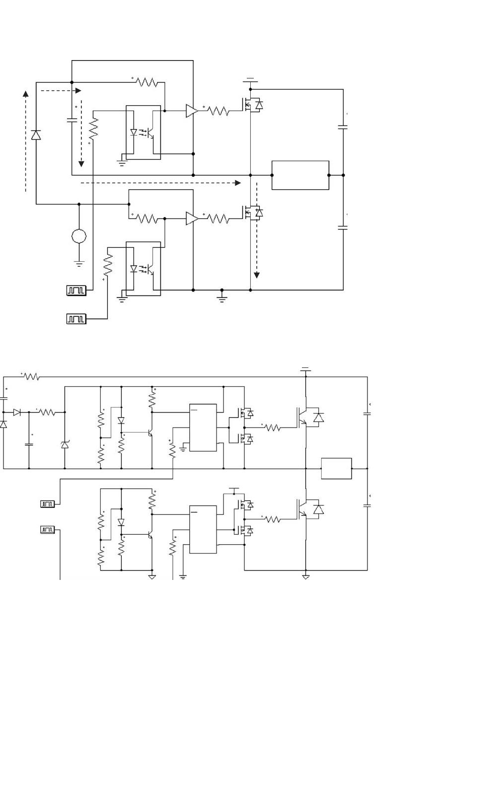
Gate Driver with Bootstrapped Floating Supply
The addition of a bootstrapped capacitor voltage allows
for the generation of a floating supply in Fig. 20.20.
Charging of C1 is achieved in the direction indicated
during the period when MOSFET M2 is turned on. The
turn-off of M2, results in the entrapment of charge in
C1 which now acts as the power supply to OPTO1, U1,
and the MOSFET M1’s gate. As current is drawn from
C1, the capacitor voltage tends to drop and needs to
be replenished cyclically. The selection of the bootstrap
capacitor value is critical for reliable operation of this
circuit under extended duty cycle conditions. Diode D1
sees the full DC bus voltage when M2 is off, and therefore
has to have a sufficiently high breakdown voltage. Appli-
cations with fast switching speed, require that D1 be a
fast recovery diode in order to withstand the high dv/dt
present across M2. Level shifting of the switching control
signal is achieved by means of the opto-couplers in the
circuit, providing the necessary control circuit isolation
required.
• Gate Driver with Floating Supply Derived from DC Bus
When the generation of a floating supply is required with-
out the need for isolation, the gate drive power can be
derived from the DC bus voltage. The circuit is charged
during the period when IGBT1 is off, with the gate drive
energy stored in C2. The circuit connected to the enable
pin of the opto-coupler, forms an under-voltage lock-
out which inhibits the IGBT drive signal at low DC
supply voltages, typically during the initial start-up of
the inverter circuit. The control signals are level shifted
through an opto-coupler which drives a totem pole
complimentary buffer stage as shown in Fig. 20.21 [8].
20.5 Current Technologies
The evolution of power semiconductor technology has led to
the development of smart driver IC modules. These modules
offer an essentially single chip/package solution to the gate
driver designer, with the inclusion of minimal external compo-
nents. These smart driver ICs utilize sophisticated electronics,
yielding an intelligent gate driver in a small module. Some of
these functions include the electronics for generating the float-
ing supply from the auxiliary power supplied to the IC, level
shifting with or without isolation. Advanced on-board inte-
grated functions include under-voltage lockout, thermal trip,
overload and de-saturation detection, soft start, and shutdown.
These features enhance the effective utilization of the power
converter and also increase its reliability.
554 I. Khan
+
−
DC Bus
C1
D1
R1
R2
15Vdc
PWM1
PWM2
R4
R3
R5
M1
M2
C2
C3
LOAD
R6
OPTO1
OPTO2
U1
U2
FIGURE 20.20 Optically isolated level shifter with an un-isolated bootstrapped floating supply derived from the low-side power supply.
R1
R6
U1
U2
OUT
OUT
VCC
VCC
VEE
VEEB
A
EN
B
A
EN
HCPL2200
HCPL2200
M1
M3
15V
M4
R14
R13
M2
C4
C5
Load
IGBT1
IGBT2
R3
R4
R5
R10
R9
R8
R11
LED2
PWM2
PWM1
BJT1
BJT2
R7
R12
LED1
Dz1
15V
R2
C2
D2
D1
C1
DC Bus
FIGURE 20.21 Level shifted gate driver with floating supply derived from the DC bus.
20.5.1 Transformer Coupled Isolated Drivers
Semikron Corporation has developed a gate driver module
that employs integrated floating supplies (Fig. 20.22) [9]. The
level shifting is accomplished through transformer coupling,
which is used as a bi-directional communications link for the
transmission of the gate drive and fault signals.
Each module is configured for a half-bridge inverter con-
figuration and one additional driver module can be added
for each inverter leg needed. The modules come in a variety
of output current capabilities, depending on the IGBT drive
requirements, with usable operating frequencies ranging from
the low kHz range up to 30 kHz.
20 Gate Drive Circuitry for Power Converters 555
input1
(TOP)
input2
(BOTTOM)
-input buffer
-short pulse
supression
-pulse shaper
-Vs monitor
-Error monitor
-Error memory
-interlock
-deadtime
SELECT
TDT1
TDT2
Error
input
When SKH122B is driving 1700V IGBTs, a 1kW/0,4W RVCE-resistor must be connected in series to the VCE-input.
The VCE terminal is to be connected to the IGBT collector C. If the VCE-monitoring is not used, connect S1 to S9 or S20 to S12 respectively.
Terminals P5 and P6 are not existing for SKH122A/21A; internal pull-up resistor exists in SKH122A/21A only.
Connections to SEMITRANS GB-models
integrated in ASIC
V
S
V
CE
V
CE
R
CE
C
CE
R
VCE
R
VCE
V
iT
V
iB
6k8/100
6k8/100
P12
P8
P7
3k2
3k2
V
GND/OV
GND/OV
V
S
V
S
V
S
S14
S13
S12
S9
S8
S7
R
on
R
on
R
off
R
off
R
CE
C
CE
S6
S1
SEMITRANS
IGBT-Module
S15
S20
V
S
P6
P5
P9
P14
P10
P13
Isolation
over
current
Power
driver
Power
driver
over
current
primary side secondary side output
LOAD
output2
(BOTTOM)
output1
(TOP)
R
ERROR
=
=
=
=
3
4
5
1
7
2
6
FIGURE 20.22 SKHI22 integrated half-bridge IGBT module capable of operation at 1200 V. A product of the Semikron Corporation.
Voltage
Supply
Voltage
Supply
Input
Logic
CPO
CP+
CP–
OPO
OP+
OP−
OP
OP
GND
OUHLogic
High side
Low side
VSH
GNDH
OUL
VSL
GNDL
SD
InL
InH
V
co
+
−
+
−
UVLC
UVLC
Delay
Com.
Level-
shifter
FIGURE 20.23 EUPEC EICE-Driver incorporating monolithic coreless transformer technology allowing for a substantial reduction in the device size.
Another manufacturer of isolated gate driver modules is
Eupec semiconductor [10]. These modules employ a mono-
lithically integrated coreless planar transformer design in a
gate driver IC. This allows it to be substantially smaller and
cheaper [6]. These modules are operational to 60 kHz with
output current capabilities in excess of 2 A peak. The EUPEC
EICE-Driver (2ED020I12-F) is shown in Fig. 20.23.
20.5.2 Non-isolated Electronic Level
Shifted Drivers
The International Rectifier Corporation has developed a family
of low cost gate driver ICs for the power electronics industry
[11]. International Rectifiers, gate driver ICs (Fig. 20.24) utilize
electronic level shifting for conveying the switching signal to
556 I. Khan
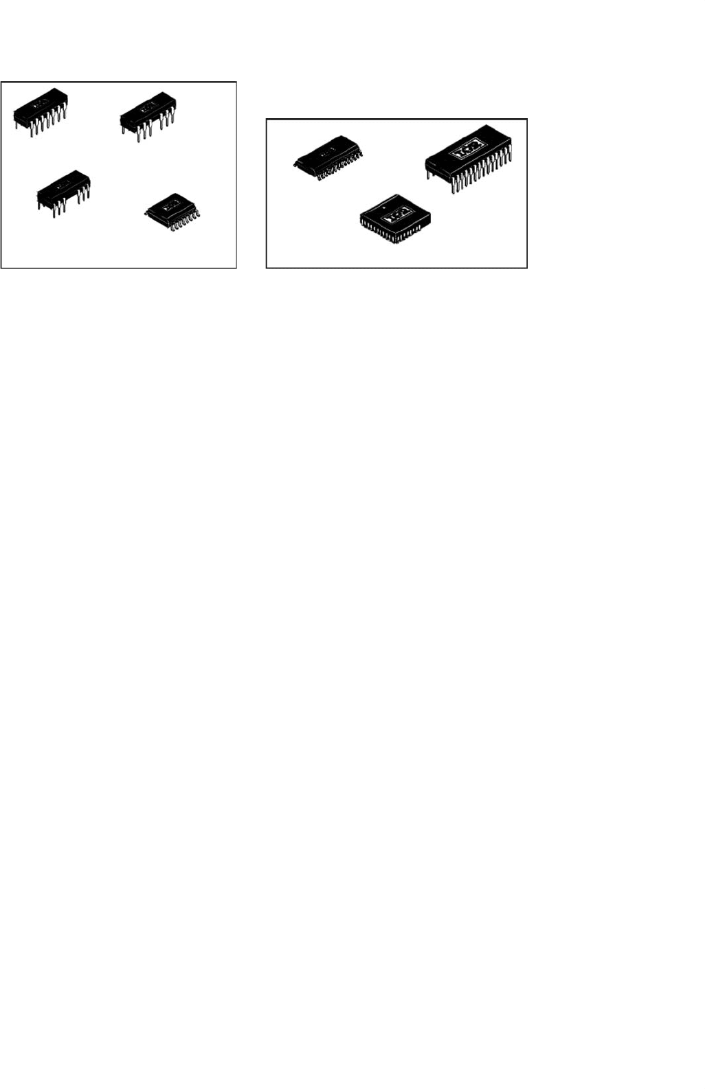
28 Lead SOIC
28 Lead PDIP
44 Lead PLCC w/o 12 leads
14 Lead PDIP
IR2110/IR2113
14 Lead PDIP
w/o Lead 4
IR2110-1/IR2113-1
16 Lead PDIP
w/o leads 4 & 5
IR2110-2/IR2113-2
16 Lead SOIC
IR2110S/IR2113S
FIGURE 20.24 International Rectifiers IR2113 (Left) and the IR2233 (Right) high voltage gate driver ICs.
the high-side switch and a bootstrap technique for the gener-
ation of a floating supply. These ICs are relatively inexpensive
and are being used mainly in the low cost consumer elec-
tronics industry. Application include Electronic Ballasts and
low to medium power inverter applications such as variable
speed drives and DC to single-phase AC backup inverter sys-
tems. Available in a single-channel, half-bridge, or three-phase
inverter driver IC, these devices require a minimum amount
of external components. Intelligent features like under voltage
lockout, shut down, and current sensing inputs are included
in the driver IC.
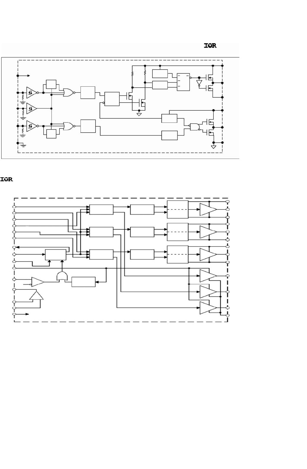
Functional diagrams of the IR2113 half-bridge driver and
the IR2233 (Three-phase full-bridge) driver are shown in
Fig. 20.25. The driver section of the IR2233 comprises a similar
structure as the IR2113’s bootstrap and level shifting circuitry.
Even though the IR range of driver ICs do not provide iso-
lation between the control and driver electronics, this device
is a low cost and very compact solution for low to medium
power applications where electrical noise and interference can
be managed by PCB circuit layout techniques. The IR2113
half-bridge driver is capable of sourcing and sinking 2 A peak
current to a capacitive load without external buffer circuitry.
This feature coupled with low propagation delay times makes
this device capable of operating at frequencies in excess of
100 kHz.
The IR2113 and IR2233 are capable of driving floating
loads (high-side switches) at 600 and 1200 V DC bus volt-
ages, respectively, making them suitable for most direct off-line
single-phase and three-phase inverter applications.
Other driver ICs available include POWEREX’s M57959L
and INTERSIL’s HIP2500 bridge driver.
20.5.3 High-speed Gate Drivers
In the quest for high conversion efficiency and high power
densities, the trend in power electronics is the move towards
high converter switching frequencies at increasingly higher
power levels. The main reason for this is to reduce the
size of the energy transfer and storage components such as
transformers, capacitors, and inductors. This results in a sub-
stantial reduction in component size and to a certain extent
also cost. Achieving the objectives of high speed and high
power switching requires fast switching power semiconduc-
tors. These devices are readily available, but as the device
die-size increases with voltage and current requirements, so
does its gate drive power requirements. This is due to an
increase in device input capacitance as the die-size is increased.
Low impedance gate driver electronics capable of delivering
gate peak drive currents to large die-size IGBTs and power
MOSFETs in excess of 8 A are often required. In order to meet
these requirements, driver ICs must be able to deliver these
large pulse currents efficiently at high switching frequencies.
This is mainly due to a limitation in the maximum allowable
device power dissipation. Device package power dissipation is
typically limited to around 1.5 W for a DIP-14 IC without heat
sinking. Many manufacturers have high speed driver solutions
which realize drivers with low output impedances such as the
TC4427 and the TC4422. These devices are available as sin-
gle or dual channel drivers capable of delivering up to 9 A
peak to a 1–10 nF capacitive load with a typical rise time of
30–50 ns. A table of available high-speed drivers from TelCom
Semiconductor Inc. is shown in Table 20.3 [12].
20.5.4 Resonant Gate Drivers
High speed gate driving requires the driver and power semi-
conductor device impedance to be as low as possible. It is
also adversely affected by parasitic inductance and capacitance
caused by incorrect layout of the gate driver circuit. Some-
times these unavoidable parasitic elements tend to increase
the gate drive loop impedance, (between the driver and the
power semiconductor device) resulting in a limitation of the
peak current drawn by the device gate. This limits the maxi-
mum achievable switching speed of the device. It also results
in uncontrolled voltage excursions on the device gate, making
high-speed driver circuit design quite challenging.
Resonant gate drivers utilize these parasitic elements in
the gate drive loop by virtue of a controlled series resonant
20 Gate Drive Circuitry for Power Converters 557
International
Rectifier
Functional Block Diagram
INPUT
SIGNAL
GENERATOR
INPUT
SIGNAL
GENERATOR
INPUT
SIGNAL
GENERATOR
FAULT
LOGIC
CURRENT
COMPARATOR
UNDER
VOLTAGE
DETECTOR
CURRENT
AMP
H1
H2
H3
L1
L2
L3
RESET
RESET
RESET
SET
SET
SET
LATCH
UV
DETECTOR
LATCH
DRIVER
DRIVER
DRIVER
DRIVER
DRIVER
DRIVER
UV
DETECTOR
LATCH
UV
DETECTOR
PULSE
GENERATOR
LEVEL
SHIFTER
PULSE
GENERATOR
LEVEL
SHIFTER
PULSE
GENERATOR
LEVEL
SHIFTER
COM
LO3
HO3
HO2
HO1
V
S2
V
S2
V
S1
V
S1
V
S3
V
S3
LO2
LO1
FAULT
FLT-CLR
SD
V
CC
V
SS
0.5V
CAO
TRIP
CA–
CA+
LIN3
LIN2
LIN1
HIN1
HIN2
HIN3
–
+
IR2133/IR2135/IR2233/IR2235
IR2110/IR2113
Functional Block Diagram
International
Rectifier
UV
DETECT
UV
DETECT
PULSE
FILTER
PULSE
GEN
HV
LEVEL
SHIFT
V
DD
/V
CC
LEVEL
SHIFT
V
DD
/V
CC
LEVEL
SHIFT
DELAY
R
R
Q
Q
S
S
R
R
Q
S
SD
LIN
HIN
V
DD
V
SS
HO
LO
COM
V
B
V
CC
V
S
FIGURE 20.25 Functional diagrams of the IR2113 half-bridge driver and the IR2233 three-phase full-bridge driver.
mode of operation. The resonant circuit comprises the driver
resistance (which is small), the device input capacitance, and
its internal gate electrode resistance. By the addition of a
defined amount of extra inductance to the gate drive loop,
the voltage swing and switching speed of the gate driver can
be controlled. A typical resonant gate driver for large die-
power semiconductors has been developed by Turboswitchers
Inc. A resonant gate driver called the TD-000, employs a
patented low loss capacitance driver circuit topology, that
reduces the driver power losses to less than half that of
conventional high-speed drivers, at all switching frequencies.
Operational from a 5 V supply, the driver is capable of high-
switching speeds and generates a gate drive voltage swing
of up to +24 to −19 V, depending on the inductance val-
ues used. Performance tests show that the TD-000 driver is
capable of switching a 500 V/32 A power MOSFET supplied
from a 400 V DC bus, in less than 3 ns. This switching speed
allows for power electronic converters operating well into the
MHz range. Detailed device application information can be
found in [13].

558 I. Khan
TABLE 20.3 High current high-speed driver ICs available from TelCom semiconductor
Device no. Drive
current
(Peak)
Output number and type Rated
load
(pF)
Rise time
@ rated
load
(ns)
Fall time
@ rated
load
(ns)
Rising edge
propogation
delay
(ns)
Falling edge
propogation
delay
(ns)
Latch-up
proof
Input
protected
to 5V
below
Gnd rail
Inverting Non-inverting
TC1426 1.2 A Dual – 1000 30 20 55 80 Yes No
TC1427 1.2 A – Dual 1000 30 20 55 80 Yes No
TC1428 1.2 A Single Single 1000 30 20 55 80 Yes No
TC4426 1.5 A Dual – 1000 25 25 33 38 Yes Yes
TC4427 1.5 A – Dual 1000 25 25 33 38 Yes Yes
TC4428 1.5 A Single Single 1000 25 25 33 38 Yes Yes
TC4423 3.0 A Dual – 2200 25 25 33 38 Yes Yes
TC4424 3.0 A – Dual 2200 25 25 33 38 Yes Yes
TC4425 3.0 A Single Single 2200 25 25 33 38 Yes Yes
TC4420 6.0 A Single Non-invert 4700 40 35 50 55 Yes Yes
TC4429 6.0 A Single Inverting 4700 40 35 50 55 Yes Yes
TC4421 9.0 A Single – 10,000 50 48 30 33 Yes Yes
TC4422 9.0 A Single 10,000 50 48 30 33 Yes Yes
TC4469 1.2 A – Quad – 1000 30 30 35 35 Yes Yes
TC4468 1.2 A – Quad AND – 1000 30 30 35 35 Yes Yes
TC4467 1.2 A – Quad NAND – 1000 30 30 35 35 Yes Yes
20.6 Current and Future Trends
Integrated power electronic solutions have become the current
trend for applications with the development of Smart Power
modules. These modules contain the entire inverter semicon-
ductor stack as well as fully integrated gate drive circuitry.
This technology eliminates the challenges of inverter and gate
drive design and allows for fast turnaround times in new prod-
uct development through rapid prototyping. These devices are
available for low to medium power applications and have an
operating frequency limit of about 20 kHz.
Power semiconductor device manufacturers are constantly
developing better die-structures for their power MOSFETs
and IGBTs. This is to reduce device input capacitance, result-
ing in lower gate drive power requirements at high switching
speeds.
20.7 Summary
The aim of this chapter was to expose the reader to the basic
concepts, circuits, and technologies for gate drives in power
converters. The main focus has been on voltage-controlled
devices like power MOSFETs and IGBTs. Once the reader
gains a basic understanding of the concepts and available solu-
tions, detailed design information on gate drivers can be found
on the device manufacturer’s website. This is usually found
under technical application notes or technical white papers.
Other useful websites for power electronic design forums and
application-specific information can be found in [2, 14]. The
circuits presented can be adapted for the driving of other
devices such as SCRs and power BJTs.
References
1. N. Mohan, T. Undeland, and W. Robbins, “Power Electronics:
Converters, Applications and Design”, Wiley, Brisbane, 1989.
2. www.powerdesigners.com
3. D. R. H. Carter, “Aspects of High Frequency Half-Bridge Circuits”,
PhD Thesis, Cambridge University, September 1996.
4. S. Clement and A. Dubhashi, “HV Floating MOS-Gate Driver IC”,
Integrated circuit designers manual.
5. Application Note, “Hints and Applications” Design manual,
Chapter 3, Semikron Corporation.
6. M. Munzer, W. Ademmer, B. Strazalkowski, and K. T. Kaschani,
“Coreless Transformer a New Technology for Half Bridge Driver
IC’s”, application note, 2005, www.eupec.com.
7. I. de Vries, “High Power and High Frequency Class-DE Inverters”,
PhD Thesis, Department of Electrical Engineering, University of Cape
Town, August 1999.
8. Application Note AN-937, “Gate Drive Characteristics and Require-
ments for HEXFET Power MOSFETs”, www.irf.com.
9. Data sheet, SKHI22, www.semikron.com.
10. www.eupec.com
11. www.irf.com
12. Application Note 30, “Matching MOSFET drivers to MOSFETs”,
TelCom Semiconductor Inc.
13. I. de Vries, “Using Turbodriver-000”, application note, February
2002, www.turboswitchers.com.
14. www.smpstech.com

21
Power Electronics in Capacitor
Charging Applications
William C. Dillard, Ph.D.
Archangel Systems, Incorporated
1635 Pumphrey Avenue Auburn,
Alabama, USA
21.1 Introduction .......................................................................................... 559
21.2 High Voltage DC Power Supply with Charging Resistor................................. 560
21.3 Resonance Charging ................................................................................ 561
21.4 Switching Converters............................................................................... 562
References ............................................................................................. 564
21.1 Introduction
Conventional dc power supplies operate at a given dc out-
put voltage into a constant or near constant load. Pulse loads
such as lasers, flashlamps, railguns, and radar, however, require
short but intense bursts of energy. Typically, this energy is
stored in a capacitor and then released into the load. The
rate at which the capacitor is charged and discharged is called
the repetition rate, T, and may vary from 0.01 Hz for large
capacitor banks to a few kHz for certain lasers. Recharging the
capacitor voltage to a specified voltage is tasked to a capacitor
charging power supply (CCPS). The role of power electron-
ics devices, topologies, and charging strategies for capacitor
charging applications is presented in this chapter.
Figure 21.1 shows the voltage across the energy storage
capacitor connected to the output of a CCPS. As seen in this
figure, the CCPS has three modes of operation. The first mode
is the charging mode in which the capacitor is charged from
an initial voltage of zero to a specified final voltage. The dura-
tion of the charging mode is determined by the capacitance of
the energy storage capacitor and the rate at which the CCPS
delivers energy. The next mode of operation is the refresh
mode, which can be considered a “standby mode” where the
stored energy is simply maintained. When the output volt-
age drops below a predetermined value, the CCPS should
turn on and deliver the energy necessary to compensate for
capacitor leakage. Since refreshing is lost energy, the dura-
tion of the refresh mode should be as brief as possible. Issues
that lead to non-zero refresh times include safety margins for
worst-case charging and discharging mode times and SOA
requirements of switching devices. The final mode of operation
is the discharge mode where the load is actively discharging the
capacitor. The CCPS does not supply any energy to the load
in this mode. The amount of time the CCPS remains in this
mode is determined by how quickly the load can discharge the
capacitor.
The instantaneous output power for a CCPS varies over a
wide range in comparison to a conventional dc power sup-
ply which supplies a near constant power to its load. This is
shown in Fig. 21.2; the output power for the pulsed power
load is drawn as linear for illustration purposes only. The
charging mode is characterized by high peak power. At the
beginning of this mode, the output power is zero (i.e. there
is no voltage present but current is flowing). Thus, the load
capacitor is equivalent to a short circuit. Additionally, at the
end of the charging mode, the output power is again zero (i.e.
there is an output voltage present but no current is flowing).
Now the load capacitor is equivalent to an open circuit. The
refresh mode is typically a low power mode, because the cur-
rent required to compensate for capacitor leakage is small. The
CCPS does not supply any power during the discharge mode
when the energy storage capacitor is being discharged by the
pulsed load.
The average output power for a CCPS depends on the dis-
charge mode energy and the repetition rate of the load. It is
maximum when the energy storage capacitor is discharged
at the end of the charging mode (large voltage and current),
which corresponds to operation without a refresh mode. Since
the CCPS power is far from constant, the rating of a CCPS
is often given in kJ/s instead of kW. The kJ/s rating can be
Copyright © 2007, 2001, Elsevier Inc.
All rights reserved.
559
560 W. C. Dillard
Output Voltage
time
T
Charging
Mode
Refresh
Mode
Discharge
Mode
Repetition Rate = 1/T
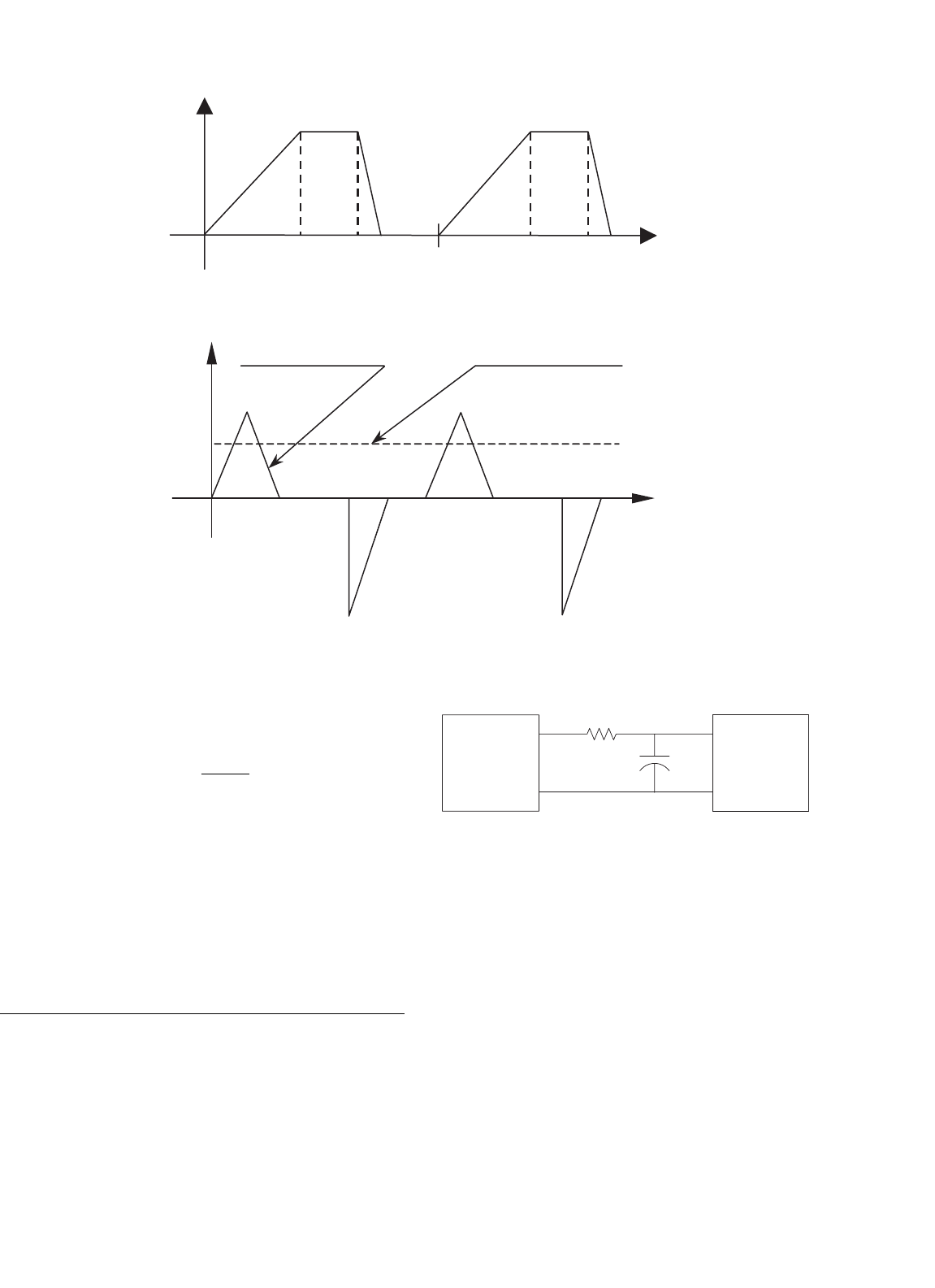
FIGURE 21.1 Three modes of operation of a capacitor charging power supply.
Power
time
Pulsed Power Load Constant Power Load
Charging
Mode
Refresh
Mode
Discharge
Mode
FIGURE 21.2 Power requirements for pulsed power and constant power loads.
written as,
kJ/s =
W
LOAD
T
where W
LOAD
is the energy delivered to the load per charging
cycle and T is the repetition rate. In the optimum case with no
refresh and instantaneous discharge, the kJ/s rating is limited
to how fast a particular capacitor can be charged by its specified
voltage.
21.2 High Voltage DC Power Supply
with Charging Resistor
In this technique, the energy storage capacitor is charged by
a high voltage dc power supply through a charging resistor
as illustrated in Fig. 21.3. The charging mode ends when the
capacitor voltage equals the output voltage of the power sup-
ply. The capacitor is continually refreshed by the power supply.
During the discharge mode, the charging resistor isolates the
High Voltage
DC Power
Supply
Pulse Load
R
C
FIGURE 21.3 High voltage dc power supply and charging resistor.
power supply from the pulse load. The advantages of this
technique are its simplicity, reliability, and low cost.
The major disadvantage of this technique is its poor effi-
ciency. In the charging mode, the energy dissipated in the
charging resistor is equal to the energy stored in the capacitor
in the ideal case; therefore the maximum efficiency is 50%. As
a result, this technique is utilized only in applications where
the charge rate is low, i.e. 200 J/s. Another disadvantage of this
technique is related to the charging time, which is determined
by the RC time constant. Some laser applications require that
the output voltage be within 0.1% of a target voltage. For this
technique, more than five time constants are required for the
capacitor voltage to meet this voltage specification.