Power electronic handbook
Подождите немного. Документ загружается.


Preface
Introduction
The purpose of Power Electronics Handbook second edition is
to provide an up-to-date reference that is both concise and
useful for engineering students and practicing professionals.
It is designed to cover a wide range of topics that make up
the field of power electronics in a well-organized and highly
informative manner. The Handbook is a careful blend of both
traditional topics and new advancements. Special emphasis is
placed on practical applications, thus, this Handbook is not a
theoretical one, but an enlightening presentation of the use-
fulness of the rapidly growing field of power electronics. The
presentation is tutorial in nature in order to enhance the value
of the book to the reader and foster a clear understanding of
the material.
The contributors to this Handbook span the globe, with
fifty-four authors from twelve different countries, some of
whom are the leading authorities in their areas of exper-
tise. All were chosen because of their intimate knowledge of
their subjects, and their contributions make this a compre-
hensive state-of-the-art guide to the expanding field of power
electronics and its applications covering:
• the characteristics of modern power semiconductor
devices, which are used as switches to perform the power
conversions from ac–dc, dc–dc, dc–ac, and ac–ac;
•
both the fundamental principles and in-depth study of
the operation, analysis, and design of various power
converters; and
• examples of recent applications of power electronics.
Power Electronics Backgrounds
The first electronics revolution began in 1948 with the inven-
tion of the silicon transistor at Bell Telephone Laboratories by
Bardeen, Bratain, and Shockley. Most of today’s advanced elec-
tronic technologies are traceable to that invention, and modern
microelectronics has evolved over the years from these sili-
con semiconductors. The second electronics revolution began
with the development of a commercial thyristor by the General
Electric Company in 1958. That was the beginning of a new
era of power electronics. Since then, many different types of
power semiconductor devices and conversion techniques have
been introduced.
The demand for energy, particularly in electrical forms, is
ever-increasing in order to improve the standard of living.
Power electronics helps with the efficient use of electricity,
thereby reducing power consumption. Semiconductor devices
are used as switches for power conversion or processing, as
are solid state electronics for efficient control of the amount of
power and energy flow. Higher efficiency and lower losses are
sought for devices for a range of applications, from microwave
ovens to high-voltage dc transmission. New devices and power
electronic systems are now evolving for even more efficient
control of power and energy.
Power electronics has already found an important place in
modern technology and has revolutionized control of power
and energy. As the voltage and current ratings and switching
characteristics of power semiconductor devices keep improv-
ing, the range of applications continues to expand in areas such
as lamp controls, power supplies to motion control, factory
automation, transportation, energy storage, multi-megawatt
industrial drives, and electric power transmission and dis-
tribution. The greater efficiency and tighter control features
of power electronics are becoming attractive for applications
in motion control by replacing the earlier electro-mechanical
and electronic systems. Applications in power transmission
include high-voltage dc (VHDC) converter stations, flexible
ac transmission system (FACTS), and static-var compensators.
In power distribution these include dc-to-ac conversion,
dynamic filters, frequency conversion, and Custom Power
System.
Almost all new electrical or electromechanical equipment,
from household air conditioners and computer power sup-
plies to industrial motor controls, contain power electronic
circuits and/or systems. In order to keep up, working engi-
neers involved in control and conversion of power and energy
into applications ranging from several hundred voltages at a
fraction of an ampere for display devices to about 10,000 V
at high-voltage dc transmission, should have a working
knowledge of power electronics.
xv

xvi Preface
Organization
The Handbook starts with an introductory chapter and moves
on to cover topics on power semiconductor devices, power
converters, applications, and peripheral issues. The book is
organized into six areas, the first of which includes Chapters 2
to 9 on operation and characterizations of power semiconduc-
tor devices: Power Diode, Thyristor, Gate Turn-off Thyristor
(GTO), Power Bipolar Transistor (BJT), Power MOSFET,
Insulated Gate Bipolar Transistor, MOS Controlled Thyristor
(MCT), and Static Induction Devices.
The next topic area includes Chapters 10 to 20 covering
various types of power converters, the principles of opera-
tion, and the methods for the analysis and design of power
converters. This also includes gate drive circuits and con-
trol methods for power converters. The next 13 chapters
21 to 33 cover applications in power supplies, electron-
ics ballasts, renewable energy soruces, HVDC transmission,
VAR compensation, and capacitor charging. Power Electron-
ics in Capacitor Charging Applications, Electronic Ballasts,
Power Supplies, Uninterruptible Power Supplies, Automotive
Applications of Power Electronics, Solar Power Conversion,
Power Electronics for Renewable Energy Sources, Fuel-cell
Power Electronics for Distributed Generation, Wind Turbine
Applications, HVDC Transmission, Flexible AC Transmission
Systems, Drives Types and Specifications, Motor Drives.
The following four chapters 34 to 37 focus on the Operation,
Theory, and Control Methods of Motor Drives, and Automo-
tive Systems. We then move on to three chapters 38 to 40
on Power Quality Issues, Active Filters, and EMI Effects of
Power Converters and two chapters 41 to 42 on Computer
Simulation, Packaging and Smart Power Systems.
Locating Your Topic
A table of contents is presented at the front of the book, and
each chapter begins with its own table of contents. The reader
should look over these tables of contents to become familiar
with the structure, organization, and content of the book.
Audience
The Handbook is designed to provide both students and prac-
ticing engineers with answers to questions involving the wide
spectrum of power electronics. The book can be used as a text-
book for graduate students in electrical or systems engineering,
or as a reference book for senior undergraduate students and
for engineers who are interested and involved in operation,
project management, design, and analysis of power electronics
equipment and motor drives.
Acknowledgments
This Handbook was made possible through the expertise
and dedication of outstanding authors from throughout the
world. I gratefully acknowledge the personnel at Academic
Press who produced the book, including Jane Phelan. In addi-
tion, special thanks are due to Joel D. Claypool, the executive
editor for this book.
Finally, I express my deep appreciation to my wife, Fatema
Rashid, who graciously puts up with my publication activities.
Muhammad H. Rashid, Editor-in-Chief

1
Introduction
Philip T. Krein, Ph.D.
Department of Electrical and
Computer Engineering,
University of Illinois, Urbana,
Illinois, USA
1.1 Power Electronics Defined........................................................................ 1
1.2 Key Characteristics.................................................................................. 2
1.2.1 The Efficiency Objective – The Switch • 1.2.2 The Reliability Objective – Simplicity
and Integration
1.3 Trends in Power Supplies ......................................................................... 4
1.4 Conversion Examples .............................................................................. 4
1.4.1 Single-Switch Circuits • 1.4.2 The Method of Energy Balance
1.5 Tools for Analysis and Design ................................................................... 7
1.5.1 The Switch Matrix • 1.5.2 Implications of Kirchhoff’s Voltage and Current Laws •
1.5.3 Resolving the Hardware Problem – Semiconductor Devices • 1.5.4 Resolving the Software
Problem – Switching Functions • 1.5.5 Resolving the Interface Problem – Lossless Filter Design
1.6 Summary .............................................................................................. 13
References ............................................................................................. 13
1.1 Power Electronics Defined
1
It has been said that people do not use electricity, but
rather they use communication, light, mechanical work, enter-
tainment, and all the tangible benefits of both energy and
electronics. In this sense, electrical engineering as a discipline
is much involved in energy conversion and information. In the
general world of electronics engineering, the circuits engineers
design and use are intended to convert information. This is
true of both analog and digital circuit design. In radio fre-
quency applications, energy and information are sometimes
on more equal footing, but the main function of any circuit is
information transfer.
What about the conversion and control of electrical energy
itself? Energy is a critical need in every human endeavor.
The capabilities and flexibility of modern electronics must
be brought to bear to meet the challenges of reliable,
efficient energy. It is essential to consider how electronic
circuits and systems can be applied to the challenges of
energy conversion and management. This is the framework
of power electronics, a discipline defined in terms of electrical
1
Portions of this chapter are from P. T. Krein, Elements of Power
Electronics. New York: Oxford University Press, 1998. Copyright © 1998,
Oxford University Press. Used by permission.
energy conversion, applications, and electronic devices. More
specifically,
DEFINITION
Power electronics involves the study of
electronic circuits intended to control the flow of elec-
trical energy. These circuits handle power flow at levels
much higher than the individual device ratings.
Rectifiers are probably the most familiar examples of circuits
that meet this definition. Inverters (a general term for dc–ac
converters) and dc–dc converters for power supplies are also
common applications. As shown in Fig. 1.1, power electronics
represents a median point at which the topics of energy sys-
tems, electronics, and control converge and combine [1]. Any
useful circuit design for an energy application must address
issues of both devices and control, as well as of the energy
itself. Among the unique aspects of power electronics are its
emphasis on large semiconductor devices, the application of
magnetic devices for energy storage, special control methods
that must be applied to nonlinear systems, and its fundamen-
tal place as a vital component of today’s energy systems. In
any study of electrical engineering, power electronics must be
placed on a level with digital, analog, and radio-frequency
electronics to reflect the distinctive design methods and
unique challenges.
Applications of power electronics are expanding exponen-
tially. It is not possible to build practical computers, cell
phones, cars, airplanes, industrial processes, and a host of
Copyright © 2007, 2001, Elsevier Inc.
All rights reserved.
1

2 P. T. Krein
P
o
w
e
r
a
n
d
E
n
e
r
g
y
S
y
s
t
e
m
s
a
n
d
C
o
n
t
r
o
l
S
y
s
t
e
m
O
p
e
r
a
t
i
o
n
F
e
e
d
b
a
c
k
C
o
n
t
r
o
l
S
w
i
t
c
h
C
o
n
t
r
o
l
M
o
t
o
r
D
r
i
v
e
s
P
o
w
e
r
S
u
p
p
l
i
e
s
U
t
i
l
i
t
y
N
e
t
w
o
r
k
s
POWER
ELECTRONICS
E
l
e
c
t
r
o
n
i
c
s
a
n
d
D
e
v
i
c
e
s
C
i
r
c
u
i
t
s
P
o
w
e
r
M
a
g
n
e
t
i
c
s
S
e
m
i
c
o
n
d
u
c
t
o
r
s
FIGURE 1.1 Control, energy, and power electronics are interrelated.
other everyday products without power electronics. Alterna-
tive energy systems such as wind generators, solar power,
fuel cells, and others require power electronics to function.
Technology advances such as hybrid vehicles, laptop com-
puters, microwave ovens, plasma displays, and hundreds of
other innovations were not possible until advances in power
electronics enabled their implementation. While no one can
predict the future, it is certain that power electronics will be at
the heart of fundamental energy innovations.
The history of power electronics [2–5] has been closely allied
with advances in electronic devices that provide the capability
to handle high power levels. Since about 1990, devices have
become so capable that a transition is being made from a
“device-driven” field to an “applications-driven” field. This
transition has been based on two factors: advanced semicon-
ductors with suitable power ratings exist for almost every
application of wide interest; and the general push toward
miniaturization is bringing advanced power electronics into
a growing variety of products. While the devices continue to
improve, their development now tends to follow innovative
applications.
1.2 Key Characteristics
All power electronic circuits manage the flow of electrical
energy between an electrical source and a load. The parts
in a circuit must direct electrical flows, not impede them. A
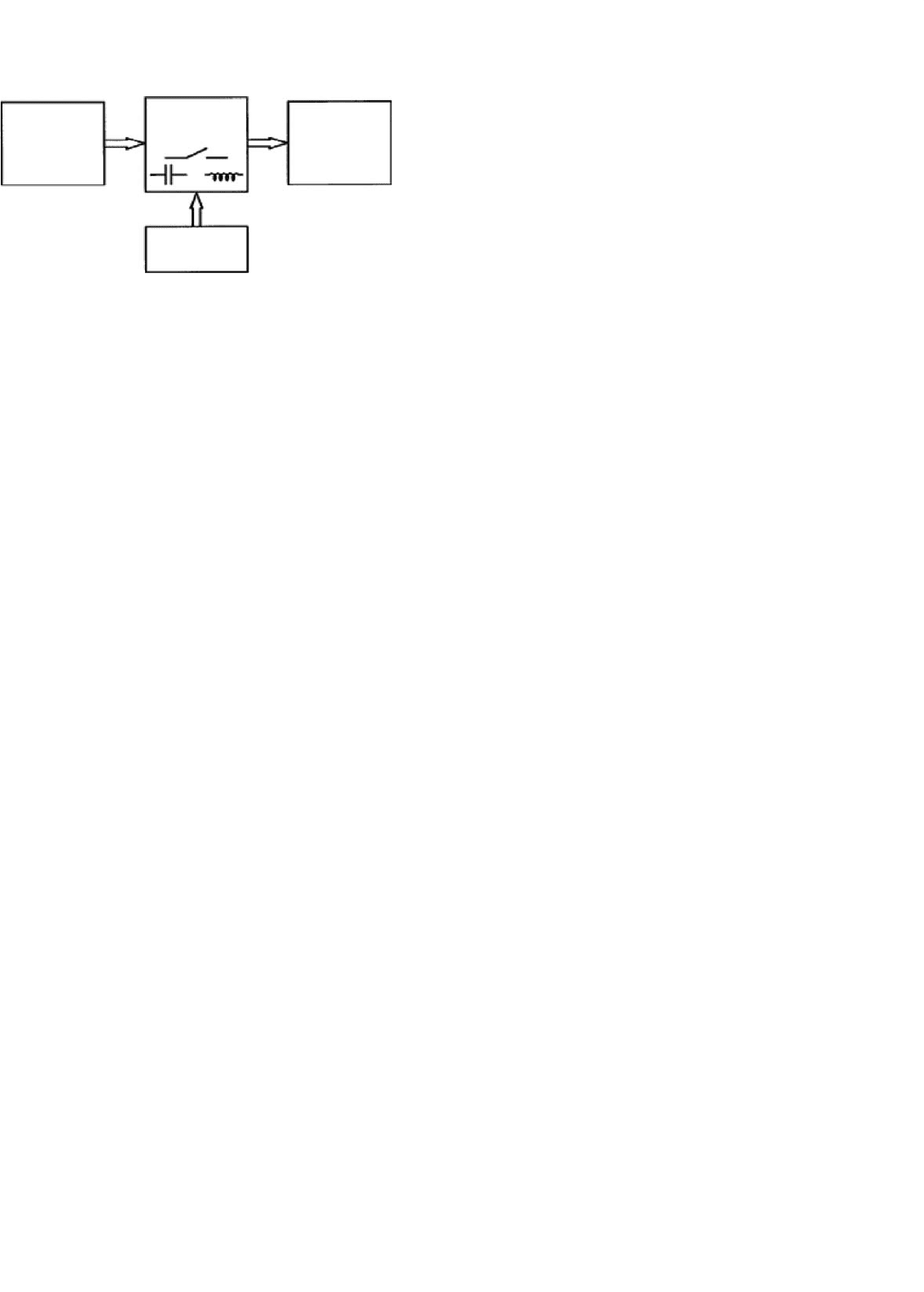
general power conversion system is shown in Fig. 1.2. The
function of the power converter in the middle is to control
the energy flow between a source and a load. For our pur-
poses, the power converter will be implemented with a power
Electrical
load
Power
converter
Electrical
energy
source
FIGURE 1.2 General system for electric power conversion. (From
Reference [2], copyright © 1998, Oxford University Press, Inc.; used by
permission.)
electronic circuit. Since a power converter appears between a
source and a load, any energy used within the converter is
lost to the overall system. A crucial point emerges: to build a
power converter, we should consider only lossless components.
A realistic converter design must approach 100% efficiency.
A power converter connected between a source and a load
also affects system reliability. If the energy source is perfectly
reliable (it is on all the time), then a failure in the converter
affects the user (the load) just as if the energy source had failed.
An unreliable power converter creates an unreliable system.
To put this in perspective, consider that a typical American
household loses electric power only a few minutes a year.
Energy is available 99.999% of the time. A converter must
be better than this to prevent system degradation. An ideal
converter implementation will not suffer any failures over its
application lifetime. Extreme high reliability can be a more
difficult objective than high efficiency.
1.2.1 The Efficiency Objective – The Switch
A circuit element as simple as a light switch reminds us that the
extreme requirements in power electronics are not especially
novel. Ideally, when a switch is on, it has zero voltage drop
and will carry any current imposed on it. When a switch is off,
it blocks the flow of current regardless of the voltage across it.
The device power, the product of the switch voltage and cur-
rent, is identically zero at all times. A switch therefore controls
energy flow with no loss. In addition, reliability is also high.
Household light switches perform over decades of use and
perhaps 100,000 operations. Unfortunately, a mechanical light
switch does not meet all practical needs. A switch in a power
supply must often function 100,000 times each second. Even
the best mechanical switch will not last beyond a few million
cycles. Semiconductor switches (without this limitation) are
the devices of choice in power converters.
A circuit built from ideal switches will be lossless. As a
result, switches are the main components of power converters,
and many people equate power electronics with the study of
switching power converters. Magnetic transformers and loss-
less storage elements such as capacitors and inductors are also
valid components for use in power converters. The complete
concept, shown in Fig. 1.3, illustrates a power electronic sys-
tem. Such a system consists of an electrical energy source, an
1 Introduction 3
Electrical
load
Power
electronic
circuit
Control
circuit
Electrical
energy
source
FIGURE 1.3 A basic power electronic system. (From Reference [2],
copyright © 1998, Oxford University Press, Inc.; used by permission.)
electrical load, a power electronic circuit, and a control func-
tion. The power electronic circuit contains switches, lossless
energy storage elements, and magnetic transformers. The con-
trols take information from the source, the load, and the
designer, and then determine how the switches operate to
achieve the desired conversion. The controls are built up with
conventional low-power analog and digital electronics.
Switching devices are selected based on their power handling
rating – the product of their voltage and current ratings –
rather than on power dissipation ratings. This is in contrast to
other applications of electronics, in which power dissipation
ratings dominate. For instance, a typical stereo receiver per-
forms a conversion from ac line input to audio output. Most
audio amplifiers do not use the techniques of power electron-
ics, and the semiconductor devices do not act as switches. A
commercial 100 W amplifier usually is designed with transis-
tors big enough to dissipate the full 100 W. The semiconductor
devices are used primarily to reconstruct the audio informa-
tion rather than to manipulate the energy flows. The sacrifice
in energy is large – a home theater amplifier often functions at
less than 10% energy efficiency. In contrast, emerging switch-
ing amplifiers do use the techniques of power electronics. They
provide dramatic efficiency improvements. A home theater
system implemented with switching amplifiers can exceed 90%
energy efficiency in a smaller, cooler package. The amplifiers
can even be packed inside the loudspeaker.
Switches can reach extreme power levels, far beyond what
might be expected for a given size. Consider the following
examples.
E
XAMPLE 1.1 The NTP30N20 is a metal oxide semi-
conductor field effect transistor (MOSFET) with a drain
current rating of 30 A, a maximum drain source break-
down voltage of 200 V, and rated power dissipation
of up to 200 W under ideal conditions. Without a
heat sink, however, the device can handle less than
2.5 W of dissipation. For power electronics purposes, the
power handling rating is 30 A × 200 V = 6 kW. Several
manufacturers have developed controllers for domes-
tic refrigerators, air conditioners, and high-end machine
tools based on this device and its relatives. The second
part of the definition of power electronics in Section 1.1
points out that the circuits handle power at levels much
higher than that of the ratings of individual devices. Here
a device is used to handle 6000 W – as compared with
its individual rating of no more than 200 W. The ratio
30:1 is high, but not unusual in power electronics con-
texts. In contrast, the same ratio in a conventional audio
amplifier is close to unity.
E
XAMPLE 1.2 The IRGPS60B120KD is an insulated
gate bipolar transistor (IGBT) – a relative of the bipolar
transistor that has been developed specifically for power
electronics – rated for 1200 V and 120 A. Its power han-
dling rating is 144 kW. This is sufficient to control an
electric or hybrid car.
1.2.2 The Reliability Objective – Simplicity
and Integration
High-power applications lead to interesting issues. In an
inverter, the semiconductors often manipulate 30 times their
power dissipation capability or more. This implies that only
about 3% of the power being controlled is lost. A small design
error, unexpected thermal problem, or minor change in layout
could alter this somewhat. For instance, if the loss turns out
to be 4% rather than 3%, the device stresses are 33% higher,
and quick failure is likely to occur. The first issue for reliability
in power electronic circuits is that of managing device voltage,
current, and power dissipation levels to keep them well within
rating limits. This can be challenging when power handling
levels are high.
The second issue for reliability is simplicity. It is well estab-
lished in electronics design that the more parts there are in
a system, the more likely it is to fail. Power electronic cir-
cuits tend to have few parts, especially in the main energy
flow paths. Necessary operations must be carried out through
shrewd use of these parts. Often, this means that sophisticated
control strategies are applied to seemingly simple conversion
circuits.
The third issue for reliability is integration. One way to
avoid the reliability-complexity tradeoff is to integrate multi-
ple components and functions on a single substrate. A micro-
processor, for example, might contain more than a million
gates. All interconnections and signals flow within a single
chip, and the reliability is nearly to that of a single part. An
important parallel trend in power electronic devices involves
the integrated module [6]. Manufacturers seek ways to pack-
age several switching devices, with their interconnections and
protection components, together as a unit. Control circuits
for converters are also integrated as much as possible to keep
the reliability high. The package itself becomes a fourth issue
for reliability, and one that is a subject of active research.
Many semiconductor packages include small bonding wires
that can be susceptible to thermal or vibration damage.

4 P. T. Krein
The small geometries tend to enhance electromagnetic
interference among the internal circuit components.
1.3 Trends in Power Supplies
Two distinct trends drive electronic power supplies, one of
the major classes of power electronic circuits. At the high end,
microprocessors, memory chips, and other advanced digital
circuits require increasing power levels and increasing perfor-
mance at very low voltage. It is a challenge to deliver 100 A
or more efficiently at voltages that can be less than 1 V. These
types of power supplies are asked to deliver precise voltages
even though the load can change by an order of magnitude in
a few nanoseconds.
At the other end is the explosive growth of portable devices
with rechargeable batteries. The power supplies for these
devices, for televisions, and for many other consumer products
must be cheap and efficient. Losses in low-cost power supplies
are a problem today; often low-end power supplies and battery
chargers draw energy even when their load is off. It is increas-
ingly important to use the best possible power electronics
design techniques for these supplies to save energy while min-
imizing the costs. Efficiency standards such as the EnergyStar®
program place increasingly stringent requirements on a wide
range of low-end power supplies.
In the past, bulky “linear” power supplies were designed
with transformers and rectifiers from the ac line frequency to
provide low level dc voltages for electronic circuits. Late in
the 1960s, use of dc sources in aerospace applications led to
the development of power electronic dc–dc conversion cir-
cuits for power supplies. In a well-designed power electronics
arrangement today, called a switch-mode power supply,anac
source from a wall outlet is rectified without direct transfor-
mation. The resulting high dc voltage is converted through a
dc–dc converter to the 3, 5, and 12 V, or other level required.
Switch-mode power supplies to continue to supplant lin-
ear supplies across the full spectrum of circuit applications.
A personal computer commonly requires three different 5 V
supplies, a 3.3 V supply, two 12 V supplies, a −12 V supply,
a 24 V supply, and a separate converter for 1 V delivery to the
microprocessor. This does not include supplies for the video
display or peripheral devices. Only a switch-mode supply can
support such complex requirements with acceptable costs.
Switch-mode supplies often take advantage of MOSFET
semiconductor technology. Trends toward high reliability, low
cost, and miniaturization have reached the point at which
a 5 V power supply sold today might last 1,000,000 h (more
than a century), provide 100 W of output in a package with
volume less than 15 cm
3
, and sell for a price approaching
US$ 0.10 per watt. This type of supply brings an interest-
ing dilemma: the ac line cord to plug it in takes up more
space than the power supply itself. Innovative concepts such
as integrating a power supply within a connection cable will
be used in the future.
Device technology for power supplies is also being driven by
expanding needs in the automotive and telecommunications
industries as well as in markets for portable equipment. The
automotive industry is making a transition to higher voltages
to handle increasing electric power needs. Power conversion
for this industry must be cost effective, yet rugged enough
to survive the high vibration and wide temperature range
to which a passenger car is exposed. Global communication
is possible only when sophisticated equipment can be used
almost anywhere. This brings a special challenge, because elec-
trical supplies are neither reliable nor consistent throughout
much of the world. While in North America voltage swings
in the domestic ac supply are often ±5% around a nominal
value, in many developing nations the swing can be ±25% –
when power is available. Power converters for communica-
tions equipment must tolerate these swings, and must also
be able to make use of a wide range of possible backup
sources. Given the enormous size of worldwide markets for
telephones and consumer electronics, there is a clear need for
flexible-source equipment. Designers are challenged to obtain
maximum performance from small batteries, and to create
equipment with minimal energy requirements.
1.4 Conversion Examples
1.4.1 Single-Switch Circuits
Electrical energy sources take the form of dc voltage sources
at various values, sinusoidal ac sources, polyphase sources,
and many others. A power electronic circuit might be asked
to transfer energy between two different dc voltage levels,
between an ac source and a dc load, or between sources at
different frequencies. It might be used to adjust an output
voltage or power level, drive a nonlinear load, or control a
load current. In this section, a few basic converter arrange-
ments are introduced and energy conservation provides a tool
for analysis.
E
XAMPLE 1.3 Consider the circuit shown in Fig. 1.4.
It contains an ac source, a switch, and a resistive load.
It is a simple but complete power electronic system.
+
−
V
out
V
ac
R
FIGURE 1.4 A simple power electronic system. (From Reference [2],
copyright © 1998, Oxford University Press, Inc.; used by permission.)
1 Introduction 5
1
0
180 360 540 720 900 1080 1260 1440
ac input voltage
Output voltage
Angle
(degrees)
0
Relative voltage
0.5
−0.5
−1
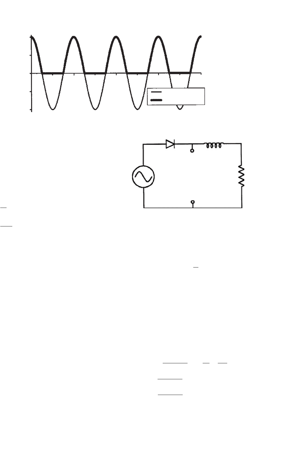
FIGURE 1.5 Input and output waveforms for Example 1.4.
Let us assign a (somewhat arbitrary) control scheme to
the switch. What if the switch is turned on whenever
V
ac
> 0, and turned off otherwise? The input and out-
put voltage waveforms are shown in Fig. 1.5. The input
has a time average of 0, and root-mean-square (RMS)
value equal to V
peak
/
√
2, where V
peak
is the maximum
value of V
ac
. The output has a nonzero average value
given by
v
out
(t)=
1
2π
π/2
−π/2
V
peak
cosθdθ+
3π/2
π/2
0dθ
=
V
peak
π
=0.3183V
peak
(1.1)
and an RMS value equal to V
peak
/2. Since the output
has nonzero dc voltage content, the circuit can be used
as an ac–dc converter. To make it more useful, a low-
pass filter would be added between the output and the
load to smooth out the ac portion. This filter needs to
be lossless, and will be constructed from only inductors
and capacitors.
The circuit in Example 1.3 acts as a half-wave rectifier with a
resistive load. With the hypothesized switch action, a diode
can substitute for the ideal switch. The example confirms
that a simple switching circuit can perform power conversion
functions. But, notice that a diode is not, in general, the same
as an ideal switch. A diode places restrictions on the current
direction, while a true switch would not. An ideal switch allows
control over whether it is on or off, while a diode’s operation
is constrained by circuit variables.
Consider a second half-wave circuit, now with a series L–R
load, shown in Fig. 1.6.
E
XAMPLE 1.4 A series diode L–R circuit has ac voltage
source input. This circuit operates much differently than
the half-wave rectifier with resistive load. A diode will
be on if forward biased, and off if reverse biased. In this
circuit, an off diode will give current of zero. Whenever
+
−
V
d
V
ac
R
L
FIGURE 1.6 Half-wave rectifier with L–R load for Example 1.5.
the diode is on, the circuit is the ac source with L–R
load. Let the ac voltage be V
0
cos(ωt ). From Kirchhoff’s
Voltage Law (KVL),
V
0
cos(ωt ) = L
di
dt
+Ri
Let us assume that the diode is initially off (this assump-
tion is arbitrary, and we will check it as the example
is solved). If the diode is off, the diode current i = 0,
and the voltage across the diode will be v
ac
. The diode
will become forward-biased when v
ac
becomes positive.
The diode will turn on when the input voltage makes
a zero-crossing in the positive direction. This allows us
to establish initial conditions for the circuit: i(t
0
) = 0,
t
0
=−π/(2ω). The differential equation can be solved
in a conventional way to give
i(t) = V
0
ωL
R
2
+ω
2
L
2
exp
−t
τ
−
π
2ωτ
+
R
R
2
+ω
2
L
2
cos(ωt )
+
ωL
R
2
+ω
2
L
2
sin(ωt)
(1.2)
6 P. T. Krein
−1
−0.5
0
0
π
2π
ac input
voltage
Current
Angle (rad)
V
d
3π
4π
5π
6π
Relative voltage and current
0.5
1
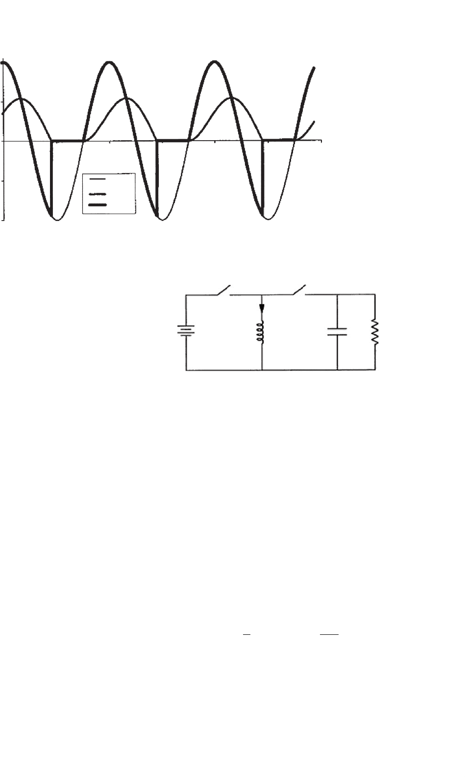
FIGURE 1.7 Input and output waveforms for Example 1.5.
where τ is the time constant L/R. What about diode
turn off? One first guess might be that the diode turns
off when the voltage becomes negative, but this is not
correct. From the solution, the current is not zero when
the voltage first becomes negative. If the switch attempts
to turn off, it must drop the inductor current to zero
instantly. The derivative of current in the inductor, di/dt,
would become negative infinite. The inductor voltage
L(di/dt) similarly becomes negative infinite – and the
devices are destroyed. What really happens is that the
falling current allows the inductor to maintain forward
bias on the diode. The diode will turn off only when
the current reaches zero. A diode has definite properties
that determine the circuit action, and both the voltage
and current are relevant. Figure 1.7 shows the input and
output waveforms for a time constant τ equal to about
one-third of the ac waveform period.
1.4.2 The Method of Energy Balance
Any circuit must satisfy conservation of energy. In a loss-
less power electronic circuit, energy is delivered from source
to load, possibly through an intermediate storage step. The
energy flow must balance over time such that the energy drawn
from the source matches that delivered to the load. The con-
verter in Fig. 1.8 serves as an example of how the method of
energy balance can be used to analyze circuit operation.
E
XAMPLE 1.5 The switches in the circuit of Fig. 1.8 are
controlled cyclically to operate in alternation: when the
left switch is on, the right one is off, and so on. What
does the circuit do if each switch operates half the time?
The inductor and capacitor have large values.
When the left switch is on, the source voltage V
in
appears across the inductor. When the right switch is on,
i
L
V
in
V
out
CR
+
−
FIGURE 1.8 Energy transfer switching circuit for Example 1.5. (From
Reference [2], copyright © 1998, Oxford University Press, Inc.; used by
permission.)
the output voltage V
out
appears across the inductor.
If this circuit is to be a useful converter, we want the
inductor to receive energy from the source, then deliver
it to the load without loss. Over time, this means that
energy does not build up in the inductor (instead it flows
through on average). The power into the inductor there-
fore must equal the power out, at least over a cycle.
Therefore, the average power in should equal the aver-
age power out of the inductor. Let us denote the inductor
current as i. The input is a constant voltage source. Since
L is large, this constant voltage source will not be able to
change the inductor current quickly, and we can assume
that the inductor current is also constant. The average
power into L over the cycle period T is
P
in
=
1
T
T/2
0
V
in
idt =
V
in
i
2
(1.3)
For the average power out of L, we must be careful about
current directions. The current out of the inductor will

1 Introduction 7
have a value −i. The average output power is
P
out
=
1
T
T
T/2
−iV
out
dt =−
V
out
i
2
(1.4)
For this circuit to be useful as a converter, there is net
energy flow from the source to the load over time. The
power conservation relationship P
in
= P
out
requires
that V
out
=−V
in
.
The method of energy balance shows that when operated as
described in the example, the circuit of Fig. 1.8 serves as a
polarity reverser. The output voltage magnitude is the same
as that of the input, but the output polarity is negative with
respect to the reference node. The circuit is often used to gen-
erate a negative supply for analog circuits from a single positive
input level. Other output voltage magnitudes can be achieved
at the output if the switches alternate at unequal times.
If the inductor in the polarity reversal circuit is moved
instead to the input, a step-up function is obtained. Consider
the circuit of Fig. 1.9 in the following example.
E
XAMPLE 1.6 The switches of Fig. 1.9 are controlled
cyclically in alternation. The left switch is on for two-
third of each cycle, and the right switch for the remaining
one-third of each cycle. Determine the relationship
between V
in
and V
out
. The inductor’s energy should not
build up when the circuit is operating normally as a con-
verter. A power balance calculation can be used to relate
the input and output voltages. Again, let i be the induc-
tor current. When the left switch is on, power is injected
into the inductor. Its average value is
P
in
=
1
T
2T/3
0
V
in
idt=
2V
in
i
3
(1.5)
Power leaves the inductor when the right switch is on.
Care must be taken with respect to polarities, and the
current should be set negative to represent output power.
C
L
V
out
V
in
i
R
+
−
FIGURE 1.9 Switching converter Example 1.6. (From Reference [2],
copyright © 1998, Oxford University Press, Inc.; used by permission.)
The result is
P
out
=
1
T
T
2T/3
−(V
in
−V
out
)idt
=−
V
in
i
3
+
V
out
i
3
(1.6)
When the input and output power are equated,
2V
in
i
3
=−
V
out
i
3
+
V
out
i
3
, and 3V
in
= V
out
(1.7)
and the output voltage is found to be triple the input.
Many seasoned engineers find the dc–dc step-up func-
tion of Fig. 1.9 to be surprising. Yet Fig. 1.9 is just one
example of such action. Others (including flyback cir-
cuits related to Fig. 1.8) are used in systems ranging from
CRT electron guns to spark ignitions for automobiles.
The circuits in the preceding examples have few compo-
nents, provide useful conversion functions, and are efficient. If
the switching devices are ideal, each circuit is lossless. Over the
history of power electronics, development has tended to flow
around the discovery of such circuits: a circuit with a particular
conversion function is discovered, analyzed, and applied. As
the circuit moves from laboratory testing to a complete com-
mercial product, control, and protection functions are added.
The power portion of the circuit remains close to the original
idea. The natural question arises as to whether a systematic
approach to conversion is possible. Can we start with a desired
function and design an appropriate converter, rather than
starting from the converter and working backwards toward
the application? What underlying principles can be applied to
design and analysis? In this introductory chapter, a few of the
key concepts are introduced. Keep in mind that while many of
the circuits look deceptively simple, all are nonlinear systems
with unusual behavior.
1.5 Tools for Analysis and Design
1.5.1 The Switch Matrix
The most readily apparent difference between a power elec-
tronic circuit and other types of electronic circuits is the switch
action. In contrast to a digital circuit, the switches do not indi-
cate a logic level. Control is effected by determining the times
at which switches should operate. Whether there is just one
switch or a large group, there is a complexity limit: if a con-
verter has m inputs and n outputs, even the densest possible
collection of switches would have a single switch between each
input line and each output line. The m × n switches in the
circuit can be arranged according to their connections. The
pattern suggests a matrix, as shown in Fig. 1.10.