Popov K.I., Djokic S.S., Grgur B.N. Fundamental Aspects of Electrometallurgy
Подождите немного. Документ загружается.


162
Chapter 5
where and
Hence, for the same current density:
as illustrated in Fig. 5.10.
On the other hand the increased amplitude on the current density leads to
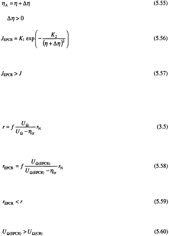
an increase of the ohmic potential drop during the pulses in EPCR relative to
constant regimes and Eq. 3.5
can be rewritten in the form:
It follows from Eq. 3.5 and Eq. 5.58 that:
because with increasing p
Hence, the increasing nucleation density is also due to the decreasing
zero nucleation zone radii. This effect leads to an increased coverage of the
foreign substrate by the same quantity of deposited metal and to decreased
porosity, surface resistance and increased density of deposit. Also, it can be
expected that increase in compactness is associated with a decrease in
internal stresses and increased ductility and hardness of metal deposits
7
.

5
. Electrodeposition at a Periodically Changing Rate
163
5.4.2 Electrode surface coarsening
The general equation of the polarization curve is given by:
for the flat part of an electrode and by
for the tip of a protrusion around which the lateral diffusion flux can
be neglected.
Using Eq. 5.19 in the form
it is easy to show that

164
Chapter 5
and
if
where and are the surface concentration of depositing ions on the flat
electrode surface and on the tip of a protrusion respectively.
The rate of increase at the tip of a protrusion relative to the flat surface is
given by
31
or
after substitution of and from Eqs.5.62 and 5.63 into Eq.
5.65a and further rearranging, assuming
It was shown earlier that at sufficiently high frequencies, the average
current density in electrodeposition at a periodically changing rate produces
the same concentration distribution inside the diffusion layer as a constant
current density of the same intensity. Hence, Eq. 5.65b is valid for all cases
of electrodeposition at a constant and periodically changing rate at
sufficiently high frequencies.
However, an increase in surface coarseness in deposition using a
rectangular pulsating overpotential or pulsating current is only possible
during the pulses of current or overpotential
31
and the integral form of Eq.
5.65 can be written as

5
. Electrodeposition at a Periodically Changing Rate
165
if
Equation 5.66 is valid for a pulsating current, square wave pulsating
overpotential and reversing current in the millisecond range under the
assumption that the entire surface dissolves uniformly during the pauses. The
deposits obtained by constant and pulsating overpotential in the mixed
control under other conditions are the same are shown in Fig 5.11. The
deposit obtained by pulsating overpotential is considerably less rough.
The copper deposits obtained under activation and mixed control as those
from Fig. 3.21 are shown in Fig 5.12. A considerable decrease in the grain
size of deposit obtained at low current densities (in the activation controlled
region Fig. 3.21a and Fig. 5.12a) due to the increase of the amplitude of the
overpotential relative to the corresponding value in constant overpotential
deposition, can be seen. There is no qualitative change, however, in the
structure of the deposit.
A qualitative change in the structure of the deposit appears in mixed
controlled deposition (Fig 3.21c and Fig. 5.12b). It is seen that the
protrusions caused by mass transport limitations are strongly reduced
relative to the deposits shown in Fig. 3.21c, but the grain size in enlarged. It
is obvious that the grains obtained by pulsating overpotential with current
densities belonging to the region of mixed control, Fig. 5.12b, are almost as
regular as those deposited under activation control (Fig. 5.12a). This is
obviously due to the increased degree of activation control during the
overpotential pulses and the increased grain size relative to those in Fig.
3.21b and c is due to the selective dissolution during the "off” periods. The
smaller nuclei formed during the overpotential pulse will be completely or
partially dissolved during the overpotential pause and the current density and
the current density on the partially dissolved ones during the next
overpotential pulse will be considerably lower than on larger ones because of
their more negative reversible potentials, and the growth of larger grains will
be favorized.
In this way the appearance of the deposit shown in Fig. 3.21c changes
and becomes that shown in Fig. 5.12b which was formed using PO
deposition of the same quantity of deposited metal and average current
density. It can be also seen from Fig. 5.12 that a good deposit can be
obtained by PO deposition over a wide range of current densities. This
means that in EPCR deposition current density can be considerably
increased relative to DC case.

166
Chapter 5
On the other hand, it is known that the orientation of nuclei strongly
depends on the depositing overpotential and that the electrode reaction
parameters can be different for different crystal planes. It is therefore not
surprising that the effect of structure on EPCR has been reported for many
cases. In some cases, deposits which behave as monocrystals
7
and deposits
with improved crystal perfection can be obtained.

5
. Electrodeposition at a Periodically Changing Rate
167
It is obvious that the same reasoning is valid for RC in the millisecond
range and PC. Some different situations appear in the case of RC in the
second range
32
.
The surface concentration changes during the cathodic pulse in RC
deposition in the second range according to Eq.
5.46.
where
In this case
is also valid and substitution of from Eq. 5.67 in Eq. 5.69 gives
for the tip of a protrusion and
for a position a flat surface. If all the surface is isopotential, elimination of
from Eqs. 5.70 and 5.71 and further rearranging produces

168
Chapter 5
The difference in the current densities at the tip of a protrusion and the
flat portion of the electrode is then given by:
for
Now, according to Eqs. 5.72 and 5.73 it can be written
or in the integral form:
where
for the first phase.
Assuming that the surface will dissolute uniformly during the anodic
is satisfied. The above reasoning is valid if a polycrystalline deposit is
obtained and the same derivation as in case of CO deposition can be used.
It can be seen from Fig. 5.13 that the structure of the deposit obtained by
RC in the second range is more similar to that obtained in the DC than in the
PC regime, but the surface coarseness of this deposit is considerably lower
than in DC case, being close to this in PC deposition.
This is because in RC deposition there is a considerable concentration
polarisation, producing polycrystalline deposit.
period, it is obvious that because f
(0)
= 0 and the increase in the
surface coarseness in the RC regime will be lower than in the DC regime
until the condition

5
. Electrodeposition at a Periodically Changing Rate
169
5.5 Current density and morphology distribution on a
macroprofile
The current density distribution on a macroprofile in EPCR has been
treated in several papers
7
. It seems that this distribution improves the
deposition by current waves with anodic flow but that without this flow it is
worse than in DC deposition. This behaviour can be successfully
explained
34
.
Assuming that Eq. 4.43 is valid for the flat electrode in a cell with low
anode polarization also, the current densities in the middle, j, and at the edge,
of a flat electrode in a cell with low anode polarization can be related by
if the deposition in both cases is under activation control in the Tafel region
and that the limiting diffusion current density is the same in the middle and
at the edge of the electrode, I is the cell current corresponding to j. During
the current pulses the amplitude values of current densities and current
should be substituted in Eq. 4.43 producing
where and are the amplitude values of current densities in the middle
and at the edge of electrode and is the amplitude of the current in the cell.
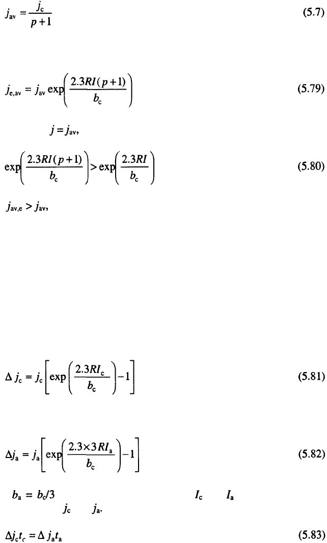
On the other hand, the amplitude in pulsating current deposition and average
current density are related by Eq. 5.7

170
Chapter 5
so Eq. 5.78 can be rewritten in the form
then meaning worse current density distribution in PC than in DC
conditions
The effect of reversing current on the current distribution at the
macroprofile level can easily be discussed for the case of activation-
controlled deposition if the Tafel slopes of the anodic and cathodic processes
are different, as they are for copper deposition and dissolution in sulphate
solutions. With the assumption that the current density in RC deposition is
sufficiently high so that the effect of the opposing processes can be
neglected, the limiting diffusion current density is the same over all
electrode surface. The difference between the current density at the edge and
that at the middle of the electrode in cathodic deposition is
and for anodic case
since for copper deposition, where and are the cell currents
assuming that if
corresponding to and It is obvious that for

5
. Electrodeposition at a Periodically Changing Rate
171
which occurs when
The best current distribution is expected in the case of PO if all the
electrode surface can be taken as an isopotential. Under the assumption that
the limiting diffusion current density does not vary over the electrode surface
area, the same current density can be expected over all points of the
electrode. A good approximation of PO deposition can be the RC deposition
by the current wave optimized relative both current density distribution on
micro and macro profile as recently shown
35
. Hence, it seams that RC should
be the optimum regime of EPCR. Besides, the crack-free chromium deposits
with improved current density distribution on both micro and macroprofile
and with practically no reduced hardness were obtained recently
36,37
, by RC
deposition. This means that the formation of unstable chromium hydride can
also be prevented by RC, but this phenomenon has been not treated
semiquantitatively so far.
(if and
deposits of equal thickness can be obtained at the
edge and at the middle of the electrode. In this way, a completely uniform
average current density distribution at the macroprofile level can be obtained
in RC deposition. The diffusion limitations of the cathodic processes will
improve the distribution in RC, but this approach is sufficient to explain the
essence of the effect, as illustrated in Fig. 5.14
34
.
