Morris & Fan. Reservoir Sedimentation Handbook
Подождите немного. Документ загружается.

HYDRAULICS OF SEDIMENT TRANSPORT 9.24
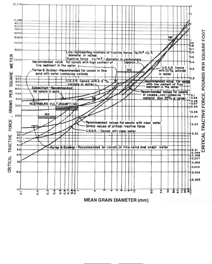
FIGURE 9.9 Allowable tractive force in channels as a function of grain size (Lane, 1955).
part
icle diameter cubed d
3
. Thus, the Shields parameter F
*
may be computed by:
F
0
d
2
(
s
)d
3
0
(
s
)d
(9.22)
The simplified form on the right-hand side is the value of the ordinate axis on the Shields
diagram. The relationship between the Shields parameter and the boundary shear
Reynolds number for the critical condition has been determined experimentally by testing
uniformly graded sediments in hydraulic flumes. In beds of mixed sediment, it has been
customary to use the d
50
sediment grain size to represent the bed behavior. However,
some researchers feel that a diameter larger than d
50
is more appropriate for describing the
effective initiation of motion in a mixed bed, as discussed in Sec. 9.7.9.
HYDRAULICS OF SEDIMENT TRANSPORT 9.25
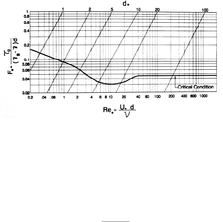
FIGURE 9.10 Modified Shields diagram for incipient sediment motion showing curves plotted by
Yalin and Karahan (1979). An exact value for the Shields parameter cannot be given at any point
b
ecause there is significant scatter in the experimental data from which the curve is derived, and the
exact shape of the resulting curve reflects interpretations by different researchers.
Use
of the Shields diagram requires that the critical value of the Shields parameter F.
cr
be
determined. However, problem-solving with the Shields curve is not straightforward.
Since the grain diameter d appears on both axes, a trial-and-error solution can be
required. To facilitate computations when grain size is known, the dimensionless
diameter d
*
(top axis in Fig. 9.10) may be computed (Julien, 1995):
3/1
2
)1(
v
gG
dd
s
(9.23)
where d = sediment diameter (m, ft), G
s
= specific gravity of sediment, and v = kinematic
viscosity. Because d
*
is dimensionless, Eq. (9.23) may be solved using either SI or fps
units. With d
*
determined, the F
*cr
value may be read from the Shields diagram, and the
critical value for bed shear stress
cr
is computed by substituting into Eq. (9.22). Values of
critical shear stress as a function of grain diameter, computed using this method, are
plotted in Fig. 9.11 and can be used as a guide to estimate the condition of initiation of
motion.
When grain diameter is not known, compute the shear stress by Eq. (9.16), estimate
the grain diameter [using Eq. (9.18) or Fig. 9.11], and use this to solve for the appropriate
Re. or F.
cr
value, with which F.
cr
may be determined from Fig. 9.10. Since many
hydraulic engineering problems deal with flow in the turbulent range and sediment
having d> 1 mm, computations may often be initiated by assuming that F.
cr
= 0.047, the
approximate value for the dimensionless shear stress in the range of boundary Reynolds
number Re
>40 (Yalin and Karahan, 1979). For this condition Eq. (9.22) is rearranged as
HYDRAULICS OF SEDIMENT TRANSPORT 9.26
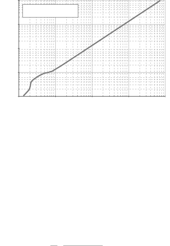
0.1
1
10
100
1000
0.1 1 10 100 1000
Grain Diameter (mm)
Critical Bed Shear Stress (N/m
2
)
Initiation of Motion
Cohesionless Sediment
FIGURE 9.11 Approximate bed shear stress required to initiate
p
article motion on a uniform bed o
f
cohesionless sediment (based on Julien, 1995) for 20°C, specific gravity of sediment = 2.65.
c
r
F
(
s
y)d
0.047(
s
)d
By substitution solve for either
0
=
cr
or d = d
cr
.
Substitute the resulting d value back
into the expression for boundary Reynolds number [Eq. (9.9)] to check the validity of the
assumption Re
>40.
9.7.5 Velocity Criteria
Yang (1973, 1996) has argued that unit stream power is a better indicator of the condition
of incipient motion than the Shields parameter. Yang defined the dimensionless critical
velocity V
cr
/ω as the ratio of the average cross-section velocity at the critical condition to
the terminal particle fall velocity for the grain size of interest. This ratio was then related
to Re
*
, the shear velocity Reynolds number, by experimental data. For the hydraulically
smooth and transition zones the incipient motion criteria is given by:
V
cr
2.5
log(V
d /v) 0.06
0.66 (9.24)
and for the hydraulically rough region the relationship is:
HYDRAULICS OF SEDIMENT TRANSPORT 9.27
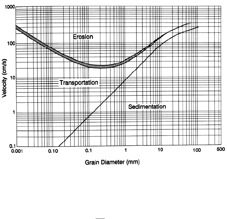
FIGURE 9.12 Velocity criterion developed by Hjulstrom in 1935 to describe
the initiation of erosion and of deposition for uniform particles.
V
cr
2.05 (9.25)
In the turbulent range, for Re
>70, Yang's expression [(Eq. 9.25)] states that particles on
a bed will begin moving when the average velocity is twice the particle settling velocity.
An approximate relationship of this type has long been recognized, and Rubey (1931)
cited work by canal engineers extending back to 1857 who observed that the competent
(nonscouring) velocities in canals tend to lie between 1 and 2 times the theoretical
settling velocity of the bed material. A graphical relationship between critical velocity
and grain size (Vanoni, 1975) is presented in Fig. 9.12.
9.7.6 Annandale's Erodibility Index Method
The erodibility index method developed by Annandale (1995) may be used to determine
the hydraulic conditions under which erosion will be initiated in a wide range of material,
including rock, earth with and without vegetation, engineered earth, and granular
material. This method has been only recently developed and is not time-tested. However,
unlike the other methods presented, it has the interesting potential to analyze the point of
initiation of erosion on a wide range of materials, not only loose granular sediments. It
has been used to study scour at spillways (Annandale, 1994). Of particular interest to
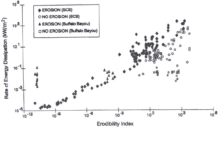
HYDRAULICS OF SEDIMENT TRANSPORT 9.28
fluvial applications, the method has been used to analyze the onset of streambank erosion
following a flood event at 44 sites along a 27-km stream corridor in Texas, with material
including fine silty sand, granular clays, riprap, bagwalls, and vegetated soils. Eroding
and noneroding conditions were successfully differentiated by the index method (Fig.
9.13).
The erodibility index method is based on stream power, V (see Appendix J), the
erosive power of water, according to the relationship:
V = f(K
h
) (9.26)
where V = stream power (W/m
2
), and f(K
h
) is the erodibility index. Erosion will occur
when V>f(K
h
), but not when V<f(K
h
). The rate of energy dissipation per unit of bed
area is computed by:
V = D S V (9.27)
where = unit weight of water, D = depth, V = velocity, and S = energy slope.
The following equation and parameters are used to determine the erodibility index or
the erosion resistance offered by any material:
K
h
= M
S
K
b
K
d
J
S
(9.28)
where M
s
= mass strength number, given in Tables 9.7 and 9.8 for granular and
cohesive soils, respectively.
K
b
= block or particle size number; refers to the mean grain size d
50
for granular
material and the mean size of blocks. For noncohesive sediment it is
computed as K
b
= 1000d
50
3
for d
50
in meters. For vegetated soils it is related
to the rooting characteristics.
FIGURE 9.13 Eroding and noneroding conditions based on the erodibility index metho
d
(Annandale, 1996).

HYDRAULICS OF SEDIMENT TRANSPORT 9.29
TABLE 9.7 Mass Strength Number for Granular Soil (M
s
)
Consistency Identification in profile
Standard
penetration
test blow
count
Mass
strength
number
M
s
Very loose 0-4 0.02
Crumbles very easily when scraped with geo-
logical pick
Loose 4-10 0.04
Small resistance to penetration by sharp end of
geological pick
Medium dense 10-30 0.09
Considerable resistance to penetration by sharp
end of geological pick
Dense 30-50 0.19
Very high resistance to penetration of sharp end
of geological pick; requires many blows of pick
for excavation
Very dense 50-80 0.41
High resistance to repeated blows of geological
pick; requires power ols for excavation to
Source: Annandale (1995)
TABLE 9.8 Mass Strength Number for Cohesive Soil (M
s
)
Consistency Identification
Vane shear
strength,
kPa
Mass
Strength
number
M
s
Very soft
Pick head can easily be pushed in up to the shaft of
handle; easily molded by fingers
0-80
0.02
Soft
Easily penetrated by thumb; sharp end of pick can
be pushed in 30 to 40 mm; molded by fingers with
some pressure
80-140 0.04
Firm
Indented by thumb with effort; sharp end of pick
can be pushed in up to 10 mm; very difficult to
mold with fingers; can just be penetrated with an
ordinary hand spade
140-210 0.09
Stiff
Penetrated by thumbnail; slight indentation
p
roduced by pushing pick point into soil; cannot be
molded by fingers; requires hand pick for
excavation
210-350 0.19
Very stiff
Indented by thumbnail with difficulty; slight
indentation produced by blow of pick point;
requires power tools for excavation
350-750 0.41
Source: Annandale (1995).

HYDRAULICS OF SEDIMENT TRANSPORT 9.30
K
d
= interparticle bond shear strength number, the equivalent residual friction
angle from a triaxial or vane shear test. For granular material it may be
estimated as tan 42 using angle of repose (Fig. 9.1).
J
s
= relative ground structure number. It is an expression of rock shape and
orientation and has a value of J
s
= 1 for granular or soil-type material.
We present here only the technique applicable to cohesionless granular material. For
loose granular material (0.1 to 100 mm dia.), the relationship between stream power at
the critical erosion condition TV, and the erodibility index K
h
may be expressed as
V
cr
= 480K
h
0.44
(9.29)
Erosion occurs if stream power exceeds the value of V
cr
. For cohesionless granular
material, the erodibility index value may be related to grain diameter (in mm) by:
K
h
= M
s
K
b
K
d
J
s
= (0.02)(1000d
50
3
)(tan )(1) = 20d
50
3
tan (9.30)
where = angle of repose. A worked example is given in the next section. Refer to
Annandale (1995) for guidelines for application to other earth and rock materials.
9.7.7 Example 9.1
Determine critical grain size for noncohesive sediment in a wide channel at 20°C ( =
1×10
-3
, v = 1×10
-6
) with the following characteristics: D = 0.6 m, V = 1.2 m/s, n = 0.030.
Use Manning's equation and assume R = D since the channel is wide (V = n
-1
D
2/3
S
1/2
),
and rearrange to compute S = 0.0026. Solve for bed shear stress:
0
=
DS = 9810(0.6)(0.0026) = 15.3 N/m
2
Empirical Relationships. The simplest relationship is given by Figure 9.11. Use Eq.
(9.18) by letting
0
=
cr
, compute d
50
=
cr
/0.785 = 15.3/0.785 = 19 mm. To use Figure
9.9 it is necessary to perform a unit conversion. Converting into g/m
2
gives
[15.3 kgm/(s
2
m
2
)](s
2
/9.81m)(1000g/kg)=1560 g/m
2
Or, converting into lb/ft
2
gives
(15.3 N/m
2
)(1/47.9) = 0.32 lb/ft
2
From Figure 9.9, a diameter of approximately 20 mm is obtained.
Using the diameter, determine the flow regime.
Re
U
d
v
(gRS)
1/2
d
v
0.1237(0.02)
1
10
6
2472
It is strongly turbulent; i.e., Re
>>70.
Yang's Method. In the turbulent range rearrange Eq. (9.25) to obtain:
V
cr
2.05
Let V = V
cr
; solve for
= 1.2/2.05 = 0.585 m/s. Estimating that the particle diameter is
greater than 2 mm, rearrange Eq. (5.24) to solve for the particle diameter:
HYDRAULICS OF SEDIMENT TRANSPORT 9.31
d
3.32
2
0.5852
3.32
2
0.031m 31mm
A more general case would be to solve for the diameter using the Rubey equation (5.23),
which is valid for the full range of particle diameters and includes the temperature-
dependent effect of viscosity. However, for particles in this grain size, viscosity effects
are negligible.
Shields Diagram. Let
0
=
cr
.
In the turbulent flow range, F
*cr
= 0.047 (Fig. 9.10).
Rearrange Eq. (9.22) to solve for diameter:
d
cr
F
c
r
(
s
)
15.3
0.047(25,996 9810)
0.020m 20mm
Ero
dibility Index Method. Compute stream power:
V = DSV
= (9810 kg/m
2
s
2
)(0.6 m)(0.0026)(1.2 m/s) = 18.4 W/m
2
where 1 W = 1 N
m/s. Determine the critical K
h
value from stream power by rearranging
Eq. (9.29):
K
h
V
480
2.27
6.0 10
4
Determine the value of the critical grain diameter by letting tan = 0.8 and rearranging
Eq. (9.30) to solve for diameter:
d
50
K
h
20tan
1/3
6.0 10
4
16
1/3
0.033m 33mm
9.7.8 Example 9.2
Conditions in this example are the same as those in Example 9.1, except D = 6 m. The
velocity is unchanged at V = 1.2 m/s. Use Manning's equation to solve for S = 0.00012.
Solve for bed shear stress:
0
=
DS = 9810( 6.0)(0.00012) = 7.06 N/m
2
Solve as before using the Shields curve:
d
cr
F
(
s
)
7.06
0.047(25,996 9810)
0.009m 9mm
A similar value is obtained from Fig. 9.9, Fig. 9.11, and using Eq. (9.18).
For the erodibility index method, compute stream power:
V = DSV
= (9810 kg/m
2
s
2
)(6.0 m)(0.00012)(1.2 m/s) = 8.5 W/m
2
K
h
V
480
2.27
8.5
480
2.27
1.06 10
4

HYDRAULICS OF SEDIMENT TRANSPORT 9.32
mmm
h
k
d 19019.0
3/1
16
4
1006.1
3/1
tan20
50
The above approaches all predict a reduction in the critical grain size as flow depth
increases, with average velocity remaining unchanged. However, mean velocity
approaches (as differentiated from the bottom velocity approach) will predict a grain size
identical to that in Example 9.1 because the mean velocity remains unchanged between
the two examples.
9.7.9 Initiation of Motion in Graded Sediments
Stelczer (1981) stated that the critical mean velocity of each size fraction in a mixed bed
was virtually identical to that for uniformly graded sediment. This is essentially the
assumption incorporated into mathematical sediment transport models which compute
transport of material within each size fraction separately. However, the initiation of
significant motion within a bed of mixed sediments can be affected by factors such as
hiding of smaller grains by the larger ones and armoring. Graf (1971) stated that for
sediments which are not uniformly sized or contain cohesive sediment, the critical bed
shear stress for incipient motion should be higher than predicted in the Shields diagram.
Results from experimental work in glass flumes and in the field led Stelczer (1981) to
conclude that: "The movement of bed load comprising several size fractions is controlled
overwhelmingly by the particle size around d
80
.
The smaller fractions and the larger ones
are set into motion almost simultaneously (at the same critical velocity) with the d
80
fraction. This fraction tends to shield smaller particles, whereas once these are removed,
the larger fraction loses support and is scoured by the flow." Additional information on
the initiation of motion in mixed beds is given in Sec. 18.6.4.
9.8 STABLE CHANNEL DESIGN
The incipient motion criteria discussed above apply to a flat bed. On a sloping surface,
such as the side of a channel, sediment will be inherently less stable than on a flat bed.
However, the shear stresses on straight channel sides are smaller than on the bed. These
factors must be considered to determine the stable material and allowable side slope
angle.
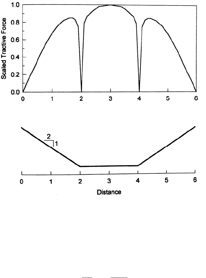
9.8.1 Shear Stress Distribution
Shear stress is not distributed evenly across a cross section. For a straight prismatic
trapezoidal channel, Lane (1953) computed the shear stress distribution shown in Fig.
9.14 and concluded that in trapezoidal channels maximum shear stress for the bottom and
sides is approximately equal to 0.97 γDS and 0.75 -γDS, respectively.
The boundary shear stress distribution for a curved trapezoidal channel was
experimentally measured by Ippen and Drinker (1962), who found that the maximum
shear stresses occur at the outer toe of the bank immediately downstream of the curve.
Shear stress in the curved reach will be 2 to 3 times greater than the shear in a straight
channel. The ratio of maximum shear in a curved reach to the shear stress in a straight
channel is given by:
max
0
0
2.65
r
c
B
0.5
(9.31)
HYDRAULICS OF SEDIMENT TRANSPORT 9.33
FIGURE 9.14 Variation in shear stress across a trapezoidal channel (Lane, 1955).
where
0
= average boundary shear stress in the approach channel, max
0
= maximum
local boundary shear in the curved reach, r
c
= centerline radius of the bend, and B = water
surface top width at the upstream end of the curved reach.
9.8.2 Slope Stability
A simplified slope stability analysis may be based on the following relationship:
cr
cr
1
sin
2
sin
2
0.5
(9.32)
where
cr
= the critical shear stress on the slope consisting of sediment or stone having
= angle of repose and = channel side slope angle (Fig. 9.1). The side slope is stable
when
slope
<
cr
. Although the side slope will tolerate a lower shear stress than the
bottom, the sides also receive less shear stress than the bed because of the uneven shear
stress distribution. Because the angle of repose increases as a function of stone size, the