Moran M.J., Shapiro H.N. Fundamentals of Engineering Thermodynamics
Подождите немного. Документ загружается.

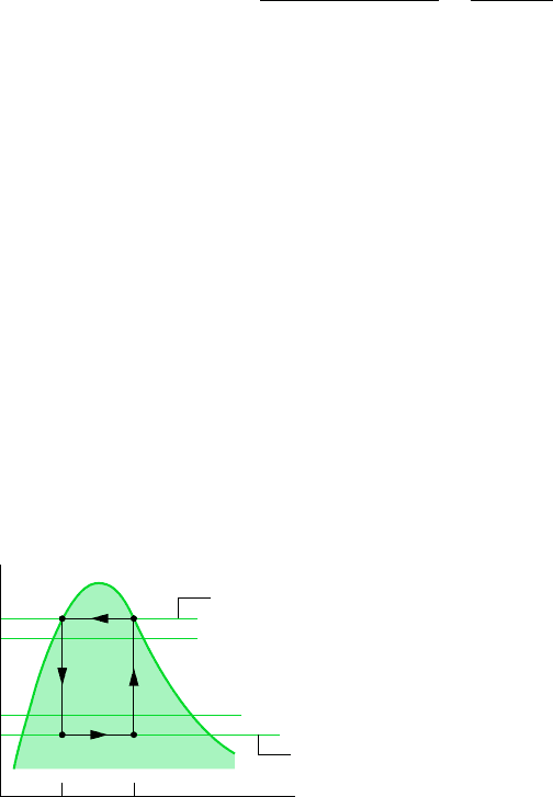
DEPARTURES FROM THE CARNOT CYCLE
Actual vapor refrigeration systems depart significantly from the Carnot cycle considered
above and have coefficients of performance lower than would be calculated from Eq. 10.1.
Three ways actual systems depart from the Carnot cycle are considered next.
One of the most significant departures is related to the heat transfers between the refrig-
erant and the two regions. In actual systems, these heat transfers are not accomplished
reversibly as presumed above. In particular, to achieve a rate of heat transfer sufficient
to maintain the temperature of the cold region at T
C
with a practical-sized evaporator
requires the temperature of the refrigerant in the evaporator, T
C
, to be several degrees
below T
C
. This is illustrated by the placement of the temperature T
C
on the T–s diagram
of Fig. 10.2. Similarly, to obtain a sufficient heat transfer rate from the refrigerant to the
warm region requires that the refrigerant temperature in the condenser, T
H
, be several
degrees above T
H
. This is illustrated by the placement of the temperature T
H
on the T–s
diagram of Fig. 10.2.
Maintaining the refrigerant temperatures in the heat exchangers at T
C
and T
H
rather
than at T
C
and T
H
, respectively, has the effect of reducing the coefficient of perform-
ance. This can be seen by expressing the coefficient of performance of the refrigeration
cycle designated by 1–2–3–4–1 on Fig. 10.2 as
(10.2)
Comparing the areas underlying the expressions for
max
and given above, we
conclude that the value of is less than
max
. This conclusion about the effect of
refrigerant temperature on the coefficient of performance also applies to other refrigera-
tion cycles considered in the chapter.
Even when the temperature differences between the refrigerant and warm and cold re-
gions are taken into consideration, there are other features that make the vapor refrigera-
tion cycle of Fig. 10.2 impractical as a prototype. Referring again to the figure, note
that the compression process from state 1 to state 2 occurs with the refrigerant as a
two-phase liquid–vapor mixture. This is commonly referred to as wet compression. Wet
compression is normally avoided because the presence of liquid droplets in the flowing
liquid–vapor mixture can damage the compressor. In actual systems, the compressor
handles vapor only. This is known as dry compression.
Another feature that makes the cycle of Fig. 10.2 impractical is the expansion
process from the saturated liquid state 3 to the low-quality, two-phase liquid–vapor
mixture state 4. This expansion produces a relatively small amount of work com-
pared to the work input in the compression process. The work output achieved by
an actual turbine would be smaller yet because turbines operating under these
b¿
area 1¿–a–b–4¿–1
area 1¿–2¿–3¿–4¿–1¿
T
¿
C
T ¿
H
T ¿
C
456 Chapter 10 Refrigeration and Heat Pump Systems
T
s
ba
Temperature of warm
region, T
H
Temperature of cold
region, T
C
Evaporator
temperature, T
C
Condenser
temperature, T
H
T
C
′
T
H
′
′
′
4′ 1′
3′ 2′
Figure 10.2 Comparison of the
condenser and evaporator temperatures
with those of the warm and cold regions.
10.2 Analyzing Vapor-Compression Refrigeration Systems 457
conditions typically have low efficiencies. Accordingly, the work output of the tur-
bine is normally sacrificed by substituting a simple throttling valve for the expansion
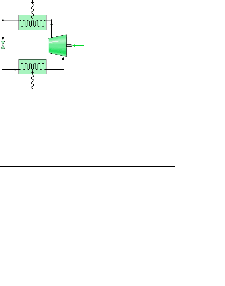
turbine, with consequent savings in initial and maintenance costs. The components of
the resulting cycle are illustrated in Fig. 10.3, where dry compression is presumed.
This cycle, known as the vapor-compression refrigeration cycle, is the subject of the
section to follow.
4
1
32
Condenser
Evaporator
Compressor
Q
out
·
Q
in
·
W
c
·
Saturated or
superheated vapor
Expansion
valve
Figure 10.3 Components of a vapor-
compression refrigeration system.
10.2 Analyzing Vapor-Compression
Refrigeration Systems
Vapor-compression refrigeration systems are the most common refrigeration systems in use
today. The object of this section is to introduce some important features of systems of this
type and to illustrate how they are modeled thermodynamically.
10.2.1 Evaluating Principal Work and Heat Transfers
Let us consider the steady-state operation of the vapor-compression system illustrated in
Fig. 10.3. Shown on the figure are the principal work and heat transfers, which are positive
in the directions of the arrows. Kinetic and potential energy changes are neglected in the
following analyses of the components. We begin with the evaporator, where the desired
refrigeration effect is achieved.
As the refrigerant passes through the evaporator, heat transfer from the refrigerated
space results in the vaporization of the refrigerant. For a control volume enclosing the
refrigerant side of the evaporator, the mass and energy rate balances reduce to give the
rate of heat transfer per unit mass of refrigerant flowing as
(10.3)
Q
#
in
m
#
h
1
h
4
vapor-compression
refrigeration

where is the mass flow rate of the refrigerant. The heat transfer rate is referred to
as the refrigeration capacity. In the SI unit system, the capacity is normally expressed
in kW. Another commonly used unit for the refrigeration capacity is the ton of refriger-
ation, which is equal to 211 kJ/min.
The refrigerant leaving the evaporator is compressed to a relatively high pressure and
temperature by the compressor. Assuming no heat transfer to or from the compressor,
the mass and energy rate balances for a control volume enclosing the compressor
give
(10.4)
where is the rate of power input per unit mass of refrigerant flowing.
Next, the refrigerant passes through the condenser, where the refrigerant condenses and
there is heat transfer from the refrigerant to the cooler surroundings. For a control vol-
ume enclosing the refrigerant side of the condenser, the rate of heat transfer from the
refrigerant per unit mass of refrigerant flowing is
(10.5)
Finally, the refrigerant at state 3 enters the expansion valve and expands to the
evaporator pressure. This process is usually modeled as a throttling process for
which
(10.6)
The refrigerant pressure decreases in the irreversible adiabatic expansion, and there is an
accompanying increase in specific entropy. The refrigerant exits the valve at state 4 as a
two-phase liquid–vapor mixture.
In the vapor-compression system, the net power input is equal to the compressor power,
since the expansion valve involves no power input or output. Using the quantities and ex-
pressions introduced above, the coefficient of performance of the vapor-compression refrig-
eration system of Fig. 10.3 is
(10.7)
Provided states 1 through 4 are fixed, Eqs. 10.3 through 10.7 can be used to evaluate the
principal work and heat transfers and the coefficient of performance of the vapor-
compression system shown in Fig. 10.3. Since these equations have been developed by
reducing mass and energy rate balances, they apply equally for actual performance when
irreversibilities are present in the evaporator, compressor, and condenser and for idealized
performance in the absence of such effects. Although irreversibilities in the evaporator,
compressor, and condenser can have a pronounced effect on overall performance, it is in-
structive to consider an idealized cycle in which they are assumed absent. Such a cycle
establishes an upper limit on the performance of the vapor-compression refrigeration cycle.
It is considered next.
10.2.2 Performance of Vapor-Compression Systems
IDEAL CYCLE. If irreversibilities within the evaporator and condenser are ignored, there are
no frictional pressure drops, and the refrigerant flows at constant pressure through the two
b
Q
#
in
m
#
W
#
c
m
#
h
1
h
4
h
2
h
1
h
4
h
3
Q
#
out
m
#
h
2
h
3
W
#
c
m
#
W
#
c
m
#
h
2
h
1
Q
#
in
m
#
458 Chapter 10 Refrigeration and Heat Pump Systems
refrigeration capacity
ton of refrigeration

10.2 Analyzing Vapor-Compression Refrigeration Systems 459
heat exchangers. If compression occurs without irreversibilities, and stray heat transfer to the
surroundings is also ignored, the compression process is isentropic. With these considera-
tions, the vapor-compression refrigeration cycle labeled 1–2s–3–4–1 on the T–s diagram of
Fig. 10.4 results. The cycle consists of the following series of processes:
Process 1–2s: Isentropic compression of the refrigerant from state 1 to the condenser pres-
sure at state 2s.
Process 2s–3: Heat transfer from the refrigerant as it flows at constant pressure through the
condenser. The refrigerant exits as a liquid at state 3.
Process 3–4: Throttling process from state 3 to a two-phase liquid–vapor mixture at 4.
Process 4–1: Heat transfer to the refrigerant as it flows at constant pressure through the
evaporator to complete the cycle.
All of the processes in the above cycle are internally reversible except for the throttling
process. Despite the inclusion of this irreversible process, the cycle is commonly referred to
as the ideal vapor-compression cycle.
The following example illustrates the application of the first and second laws of thermo-
dynamics along with property data to analyze an ideal vapor-compression cycle.
T
s
4
3
1
2s
Figure 10.4 T–s diagram of an ideal vapor-
compression cycle.
EXAMPLE 10.1 Ideal Vapor-Compression Refrigeration Cycle
Refrigerant 134a is the working fluid in an ideal vapor-compression refrigeration cycle that communicates thermally with a
cold region at 0C and a warm region at 26C. Saturated vapor enters the compressor at 0C and saturated liquid leaves the
condenser at 26C. The mass flow rate of the refrigerant is 0.08 kg/s. Determine (a) the compressor power, in kW, (b) the re-
frigeration capacity, in tons, (c) the coefficient of performance, and (d) the coefficient of performance of a Carnot refrigera-
tion cycle operating between warm and cold regions at 26 and 0C, respectively.
SOLUTION
Known: An ideal vapor-compression refrigeration cycle operates with Refrigerant 134a. The states of the refrigerant enter-
ing the compressor and leaving the condenser are specified, and the mass flow rate is given.
Find: Determine the compressor power, in kW, the refrigeration capacity, in tons, coefficient of performance, and the
coefficient of performance of a Carnot vapor refrigeration cycle operating between warm and cold regions at the specified
temperatures.
ideal vapor-
compression cycle
460 Chapter 10 Refrigeration and Heat Pump Systems
Schematic and Given Data:
4
1
32s
Condenser
Evaporator
Compressor
Q
out
·
Q
in
·
W
c
·
Warm region T
H
= 26°C = 299 K
Cold region T
C
= 0°C = 273 K
Expansion
valve
T
s
3
2s
a
41
Temperature of
warm region
Temperature of
cold region
26°C
0°C
Figure E10.1
Assumptions:
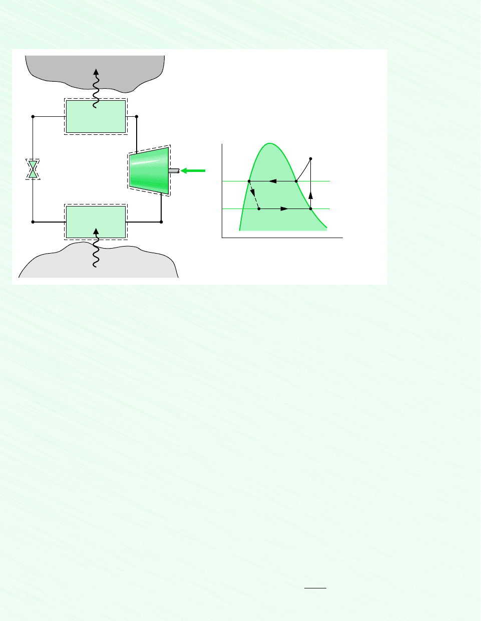
1. Each component of the cycle is analyzed as a control volume at steady state. The control volumes are indicated by dashed
lines on the accompanying sketch.
2. Except for the expansion through the valve, which is a throttling process, all processes of the refrigerant are internally
reversible.
3. The compressor and expansion valve operate adiabatically.
4. Kinetic and potential energy effects are negligible.
5. Saturated vapor enters the compressor, and saturated liquid leaves the condenser.
Analysis: Let us begin by fixing each of the principal states located on the accompanying schematic and T–s diagrams.
At the inlet to the compressor, the refrigerant is a saturated vapor at 0C, so from Table A-10, h
1
247.23 kJ/kg and s
1
0.9190
The pressure at state 2s is the saturation pressure corresponding to 26C, or p
2
6.853 bar. State 2s is fixed by p
2
and the
fact that the specific entropy is constant for the adiabatic, internally reversible compression process. The refrigerant at state
2s is a superheated vapor with h
2s
264.7 kJ/Kg.
State 3 is saturated liquid at 26C, so h
3
85.75 kJ/kg. The expansion through the valve is a throttling process (assump-
tion 2), so h
4
h
3
.
(a) The compressor work input is
where is the mass flow rate of refrigerant. Inserting values
1.4 kW
W
#
c
10.08 kg/s21264.7 247.232 kJ/kg `
1 kW
1 kJ/s
`
m
#
W
#
c
m
#
1h
2s
h
1
2
kJ/kg
#
K.
❶
10.2 Analyzing Vapor-Compression Refrigeration Systems 461
(b) The refrigeration capacity is the heat transfer rate to the refrigerant passing through the evaporator. This is given by
(c) The coefficient of performance is
(d) For a Carnot vapor refrigeration cycle operating at T
H
299 K and T
C
273 K, the coefficient of performance deter-
mined from Eq. 10.1 is
The value for h
2s
can be obtained by double interpolation in Table A-12 or by using Interactive Thermodynamics: IT.
As expected, the ideal vapor-compression cycle has a lower coefficient of performance than a Cornot cycle operating
between the temperatures of the warm and cold regions. The smaller value can be attributed to the effects of the external
irreversibility associated with desuperheating the refrigerant in the condenser (Process 2s–a on the T–s diagram) and the
internal irreversibility of the throttling process.
b
max
T
C
T
H
T
C
10.5
b
Q
#
in
W
#
c
h
1
h
4
h
2s
h
1
247.23 85.75
264.7 247.23
9.24
3.67 ton
10.08 kg/s2|60 s/min|1247.23 85.752 kJ/kg `
1 ton
211 kJ/min
`
Q
#
in
m
#
1h
1
h
4
2
❶
❷
❷
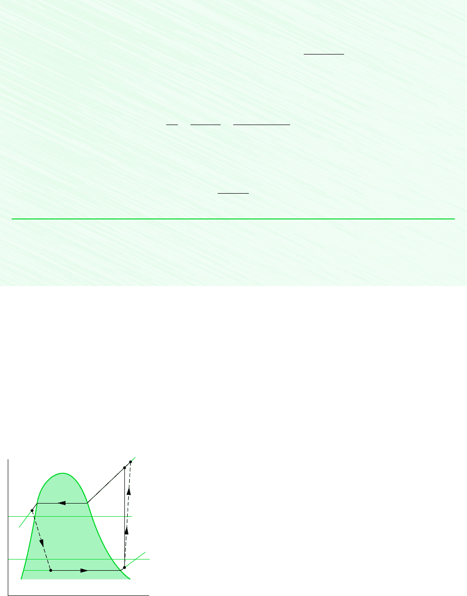
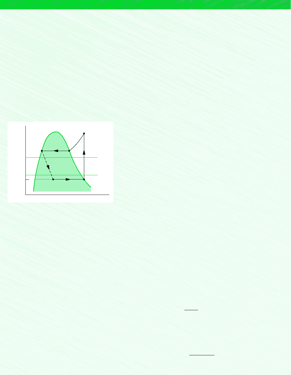
ACTUAL CYCLE. Figure 10.5 illustrates several features exhibited by actual vapor-
compression systems. As shown in the figure, the heat transfers between the refrigerant
and the warm and cold regions are not accomplished reversibly: the refrigerant tempera-
ture in the evaporator is less than the cold region temperature, T
C
, and the refrigerant
temperature in the condenser is greater than the warm region temperature, T
H
. Such irre-
versible heat transfers have a significant effect on performance. In particular, the coeffi-
cient of performance decreases as the average temperature of the refrigerant in the
evaporator decreases and as the average temperature of the refrigerant in the condenser
increases. Example 10.2 provides an illustration.
3
Temperature of
warm region, T
H
Temperature of
cold region, T
C
T
s
2
2s
4
1
Figure 10.5 T–s diagram of an
actual vapor-compression cycle.
462 Chapter 10 Refrigeration and Heat Pump Systems
EXAMPLE 10.2 Effect of Irreversible Heat Transfer on Performance
Modify Example 10.1 to allow for temperature differences between the refrigerant and the warm and cold regions as follows.
Saturated vapor enters the compressor at 10C. Saturated liquid leaves the condenser at a pressure of 9 bar. Determine for
the modified vapor-compression refrigeration cycle (a) the compressor power, in kW, (b) the refrigeration capacity, in tons,
(c) the coefficient of performance. Compare results with those of Example 10.1.
SOLUTION
Known: An ideal vapor-compression refrigeration cycle operates with Refrigerant 134a as the working fluid. The evapora-
tor temperature and condenser pressure are specified, and the mass flow rate is given.
Find: Determine the compressor power, in kW, the refrigeration capacity, in tons, and the coefficient of performance. Com-
pare results with those of Example 10.1.
Schematic and Given Data:
T
s
–10°C
0°C
26°C
3
41
2s
9 bar
Figure E10.2
Assumptions:
1. Each component of the cycle is analyzed as a control volume at steady
state. The control volumes are indicated by dashed lines on the sketch ac-
companying Example 10.1.
2. Except for the process through the expansion valve, which is a throt-
tling process, all processes of the refrigerant are internally reversible.
3. The compressor and expansion valve operate adiabatically.
4. Kinetic and potential energy effects are negligible.
5. Saturated vapor enters the compressor, and saturated liquid exits the
condenser.
Analysis: Let us begin by fixing each of the principal sates located on the accompanying T–s diagram. Starting at the
inlet to the compressor, the refrigerant is a saturated vapor at 10C, so from Table A-10, h
1
241.35 kJ/kg and s
1
0.9253
The superheated vapor at state 2s is fixed by p
2
9 bar and the fact that the specific entropy is constant for the adiabatic,
internally reversible compression process. Interpolating in Table A-12 gives h
2s
272.39 kJ/kg.
State 3 is a saturated liquid at 9 bar, so h
3
99.56 kJ/kg. The expansion through the valve is a throttling process; thus,
h
4
h
3
.
(a) The compressor power input is
where is the mass flow rate of refrigerant. Inserting values
(b) The refrigeration capacity is
3.23 ton
10.08 kg/s2060 s/min 01241.35 99.562 kJ/kg `
1 ton
211 kJ/min
`
Q
#
in
m
#
1h
1
h
4
2
2.48 kW
W
#
c
10.08 kg/s21272.39 241.352 kJ/kg `
1 kW
1 kJ/s
`
m
#
W
#
c
m
#
1h
2s
h
1
2
kJ/kg
#
K.

10.2 Analyzing Vapor-Compression Refrigeration Systems 463
Referring again to Fig. 10.5, we can identify another key feature of actual vapor-
compression system performance. This is the effect of irreversibilities during compression,
suggested by the use of a dashed line for the compression process from state 1 to state 2.
The dashed line is drawn to show the increase in specific entropy that would accompany an
adiabatic irreversible compression. Comparing cycle 1–2–3–4–1 with cycle 1–2s–3–4–1, the
refrigeration capacity would be the same for each, but the work input would be greater in
the case of irreversible compression than in the ideal cycle. Accordingly, the coefficient of
performance of cycle 1–2–3–4–1 is less than that of cycle 1–2s–3–4–1. The effect of irre-
versible compression can be accounted for by using the isentropic compressor efficiency,
which for states designated as in Fig. 10.5 is given by
Additional departures from ideality stem from frictional effects that result in pressure drops
as the refrigerant flows through the evaporator, condenser, and piping connecting the vari-
ous components. These pressure drops are not shown on the T–s diagram of Fig. 10.5 and
are ignored in subsequent discussions for simplicity.
Finally, two additional features exhibited by actual vapor-compression systems are shown
in Fig. 10.5. One is the superheated vapor condition at the evaporator exit (state 1), which
differs from the saturated vapor condition shown in Fig. 10.4. Another is the subcooling of
the condenser exit state (state 3), which differs from the saturated liquid condition shown in
Fig. 10.4.
Example 10.3 illustrates the effects of irreversible compression and condenser exit sub-
cooling on the performance of the vapor-compression refrigeration system.
h
c
1W
#
c
m
#
2
s
1W
#
c
m
#
2
h
2s
h
1
h
2
h
1
(c) The coefficient or performance is
Comparing the results of the present example with those of Example 10.1, we see that the power input required by the
compressor is greater in the present case. Furthermore, the refrigeration capacity and coefficient of performance are smaller
in this example than in Example 10.1. This illustrates the considerable influence on performance of irreversible heat transfer
between the refrigerant and the cold and warm regions.
b
Q
#
in
W
#
c
h
1
h
4
h
2s
h
1
241.35 99.56
272.39 241.35
4.57
EXAMPLE 10.3 Actual Vapor-Compression Refrigeration Cycle
Reconsider the vapor-compression refrigeration cycle of Example 10.2, but include in the analysis that the compressor has an
efficiency of 80%. Also, let the temperature of the liquid leaving the condenser be 30C. Determine for the modified cycle
(a) the compressor power, in kW, (b) the refrigeration capacity, in tons, (c) the coefficient of performance, and (d) the rates
of exergy destruction within the compressor and expansion valve, in kW, for T
0
299 K (26C).
SOLUTION
Known: A vapor-compression refrigeration cycle has a compressor efficiency of 80%.
Find: Determine the compressor power, in kW, the refrigeration capacity, in tons, the coefficient of performance, and the
rates of exergy destruction within the compressor and expansion valve, in kW.
464 Chapter 10 Refrigeration and Heat Pump Systems
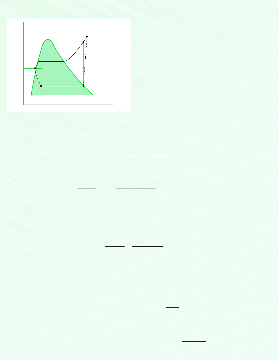
Schematic and Given Data:
30°C
–10°C
4
3
2s
2
1
T
s
T
0
= 26°C = 299 K
p
2
= 9 bar
Figure E10.3
Assumptions:
1. Each component of the cycle is analyzed as a control vol-
ume at steady state.
2. There are no pressure drops through the evaporator and
condenser.
3. The compressor operates adiabatically with an efficiency of
80%. The expansion through the valve is a throttling process.
4. Kinetic and potential energy effects are negligible.
5. Saturated vapor at 10C enters the compressor, and liquid
at 30C leaves the condenser.
6. The environment temperature for calculating exergy is T
0
299 K (26C).
Analysis: Let us begin by fixing the principal states. State 1 is the same as in Example 10.2, so h
1
241.35 kJ/kg and s
1
0.9253
Owing to the presence of irreversibilities during the adiabatic compression process, there is an increase in specific entropy
from compressor inlet to exit. The state at the compressor exit, state 2, can be fixed using the compressor efficiency
where h
2s
is the specific enthalpy at state 2s, as indicated on the accompanying T–s diagram. From the solution to Example 10.2,
h
2s
272.39 kJ/kg. Solving for h
2
and inserting known values
State 2 is fixed by the value of specific enthalpy h
2
and the pressure, p
2
9 bar. Interpolating in Table A-12, the specific en-
tropy is s
2
0.9497
The state at the condenser exit, state 3, is in the liquid region. The specific enthalpy is approximated using Eq. 3.14, to-
gether with saturated liquid data at 30C, as follows: h
3
h
f
91.49 kJ/kg. Similarly, with Eq. 6.7, s
3
s
f
0.3396
The expansion through the valve is a throttling process; thus, h
4
h
3
. The quality and specific entropy at state 4 are,
respectively
and
(a) The compressor power is
(b) The refrigeration capacity is
3.41 ton
10.08 kg/s2060 s/min 01241.35 91.492 kJ/kg
`
1 ton
211 kJ/min
`
Q
#
in
m
#
1h
1
h
4
2
10.08 kg/s2
1280.15 241.352 kJ/kg `
1 kW
1 kJ/s
` 3.1 kW
W
#
c
m
#
1h
2
h
1
2
0.1486 10.2667210.9253 0.14862 0.3557 kJ/kg
#
K
s
4
s
f4
x
4
1s
g4
s
f4
2
x
4
h
4
h
f4
h
g4
h
f4
91.49 36.97
204.39
0.2667
kJ/kg
#
K.
kJ/kg
#
K.
h
2
h
2s
h
1
h
c
h
1
1272.39 241.352
10.802
241.35 280.15 kJ/kg
h
c
1W
#
c
m
#
2
s
W
#
c
m
#
1h
2s
h
1
2
1h
2
h
1
2
kJ/kg
#
K.

10.3 Refrigerant Properties 465
(c) The coefficient of performance is
(d) The rates of exergy destruction in the compressor and expansion valve can be found by reducing the exergy rate balance
or using the relationship where is the rate of entropy production from an entropy rate balance. With either ap-
proach, the rates or exergy destruction for the compressor and valve are, respectively
Substituting values
and
Irreversibilities in the compressor result in an increased compressor power requirement compared to the isentropic com-
pression of Example 10.2. As a consequence, the coefficient of performance is lower.
The exergy destruction rates calculated in part (d) measure the effect of irreversibilities as the refrigerant flows through
the compressor and valve. The percentages of the power input (exergy input) to the compressor destroyed in the com-
pressor and valve are 18.7 and 12.6%, respectively.
1E
#
d
2
valve
10.0821299210.3557 0.33962 0.39 kW
1E
#
d
2
c
a0.08
kg
s
b 1299 K210.9497 0.92532
kJ
kg
#
K
`
1 kW
1 kJ/s
` 0.58 kW
1E
#
d
2
c
m
#
T
0
1s
2
s
1
2
and
1E
#
d
2
valve
m
#
T
0
1s
4
s
3
2
s
#
cv
E
#
d
T
0
s
#
cv
,
b
1h
1
h
4
2
1h
2
h
1
2
1241.35 91.492
1280.15 241.352
3.86
❶
❶
❷
❷
10.3 Refrigerant Properties
From about 1940 to the early 1990s, the most common class of refrigerants used in vapor-
compression refrigeration systems was the chlorine-containing CFCs (chlorofluorocarbons).
Refrigerant 12 (CCl
2
F
2
) is one of these. Owing to concern about the effects of chlorine in
refrigerants on the earth’s protective ozone layer, international agreements have been imple-
mented to phase out the use of CFCs. Classes of refrigerants containing various amounts of
hydrogen in place of chlorine atoms have been developed that have less potential to deplete
atmospheric ozone than do more fully chlorinated ones, such as Refrigerant 12. One such
class, the HFCs, contain no chlorine. Refrigerant 134a (CF
3
CH
2
F) is the HFC considered by
many to be an environmentally acceptable substitute for Refrigerant 12, and Refrigerant 134a
has replaced Refrigerant 12 in many applications.
Refrigerant 22 (CHClF
2
) is in the class called HCFCs that contains some hydrogen in
place of the chlorine atoms. Although Refrigerant 22 and other HCFCs are widely used today,
discussions are under way that will likely result in phasing out their use at some time in the
future. Ammonia (NH
3
), which was widely used in the early development of vapor-
compression refrigeration, is again receiving some interest as an alternative to the CFCs
because it contains no chlorine. Ammonia is also important in the absorption refrigeration
systems discussed in Section 10.5. Hydrocarbons such as propane (C
3
H
8
) and methane (CH
4
)
are also under investigation for use as refrigerants.
Thermodynamic property data for ammonia, propane, and Refrigerants 22 and 134a are
included in the appendix tables. These data allow us to study refrigeration and heat pump
systems in common use and to investigate some of the effects on refrigeration cycles of us-
ing alternative working fluids.
A thermodynamic property diagram widely used in the refrigeration field is the
pressure–enthalpy or p–h diagram. Figure 10.6 shows the main features of such a property
p–h diagram
