Moran M.J., Shapiro H.N. Fundamentals of Engineering Thermodynamics
Подождите немного. Документ загружается.

466 Chapter 10 Refrigeration and Heat Pump Systems
better thermoelectric
materials by alter-
nately depositing 1- to
4-nanometer films of
different materials on
the same base. These
nanoengineered ma-
terials hold promise
for cooling electronic
circuits, and perhaps
even for improved
thermoelectric coolers.
New materials are
closing the perform-
ance gap, but much re-
mains to be done be-
fore thermoelectric refrigerators are commonplace. Still, a vast
market would be served if researchers succeed.
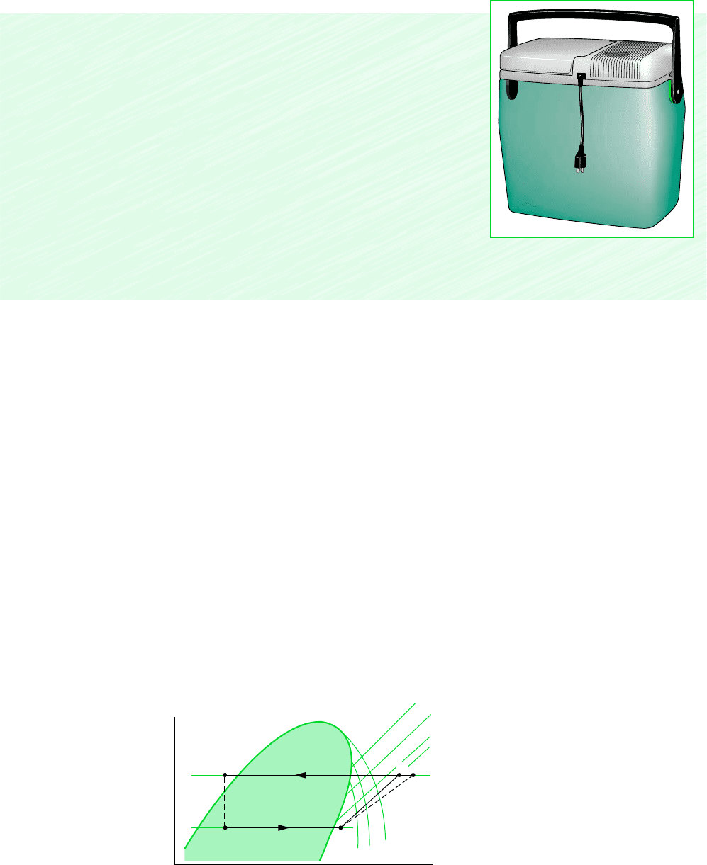
New Materials May Revive
Thermoelectric Cooling
Thermodynamics in the News...
You can buy a thermoelectric cooler powered from the ciga-
rette lighter outlet of your car. The same technology is used in
space applications. These simple coolers have no moving parts
and use no ozone-depleting refrigerants. Despite such advan-
tages, thermoelectric cooling has found only specialized ap-
plication because of low coefficients of performance that don’t
allow them to compete with commonplace vapor-compression
systems. However, new materials and novel production meth-
ods involving engineering at a nanometer level may make
thermoelectrics more competitive, material scientists say.
The basis of thermoelectric cooling is two dissimilar semi-
conductors coming together in specially designed electric
circuits. Effective materials for thermoelectric cooling must
have low thermal conductivity and high electrical conductiv-
ity, a rare combination in nature. One laboratory has produced
diagram. The principal states of the vapor-compression cycles of Fig. 10.5 are located on this
p–h diagram. It is left as an exercise to sketch the cycles of Examples 10.1, 10.2, and 10.3
on p–h diagrams. Property tables and p–h diagrams for many refrigerants are given in hand-
books dealing with refrigeration.
SELECTING REFRIGERANTS. The temperatures of the refrigerant in the evaporator and
condenser are governed by the temperatures of the cold and warm regions, respectively, with
which the system interacts thermally. This, in turn, determines the operating pressures in
the evaporator and condenser. Consequently, the selection of a refrigerant is based partly
on the suitability of its pressure–temperature relationship in the range of the particular ap-
plication. It is generally desirable to avoid excessively low pressures in the evaporator and
excessively high pressures in the condenser. Other considerations in refrigerant selection in-
clude chemical stability, toxicity, corrosiveness, and cost. The type of compressor also af-
fects the choice of refrigerant. Centrifugal compressors are best suited for low evaporator
pressures and refrigerants with large specific volumes at low pressure. Reciprocating com-
pressors perform better over large pressure ranges and are better able to handle low specific
volume refrigerants.
p
h
Condenser
pressure
Evaporator
pressure
Constant s
Constant T
1
3
4
2
2s
Figure 10.6 Principal features of the
pressure–enthalpy diagram for a typical
refrigerant, with vapor-compression cycles
superimposed.
10.4 Cascade and Multistage Vapor-Compression Systems 467
Variations of the basic vapor-compression refrigeration cycle are used to improve perform-
ance or for special applications. Two variations are presented in this section. The first is a
combined cycle arrangement in which refrigeration at relatively low temperature is achieved
through a series of vapor-compression systems, with each normally employing a different re-
frigerant. In the second variation, the work of compression is reduced through multistage
compression with intercooling between the stages. These variations are analogous to power
cycle modifications considered in Chaps. 8 and 9.
10.4.1 Cascade Cycles
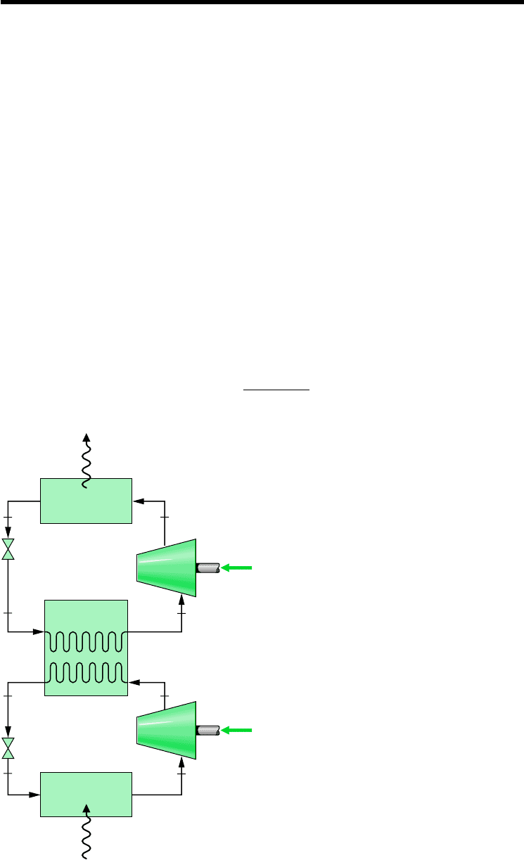
Combined cycle arrangements for refrigeration are called cascade cycles. In Fig. 10.7 a cas-
cade cycle is shown in which two vapor-compression refrigeration cycles, labeled A and B,
are arranged in series with a counterflow heat exchanger linking them. In the intermediate
heat exchanger, the energy rejected during condensation of the refrigerant in the lower-
temperature cycle A is used to evaporate the refrigerant in the higher-temperature cycle B.
The desired refrigeration effect occurs in the low-temperature evaporator, and heat rejection
from the overall cycle occurs in the high-temperature condenser. The coefficient of
performance is the ratio of the refrigeration effect to the total work input
b
Q
#
in
W
#
cA
W
#
cB
10.4 Cascade and Multistage
Vapor-Compression Systems
4
32
1
8
76
5
Low-temperature
evaporator
High-temperature
condenser
Intermediate
heat exchanger
Expansion
valve
Expansion
valve
Compressor
Compressor
Q
out
Q
in
·
Cycle A
Cycle B
W
cB
·
W
cA
·
·
Figure 10.7 Example of a cascade
vapor-compression refrigeration cycle.
The mass flow rates in cycles A and B normally would be different. However, the mass flow
rates are related by mass and energy rate balances on the interconnecting counterflow heat ex-
changer serving as the condenser for cycle A and the evaporator for cycle B. Although only two
cycles are shown in Fig. 10.7, cascade cycles may employ three or more individual cycles.
A significant feature of the cascade system illustrated in Fig. 10.7 is that the refrigerants
in the two or more stages can be selected to have reasonable evaporator and condenser pres-
sures in the two or more temperature ranges. In a double cascade system, a refrigerant would
be selected for cycle A that has a saturation pressure–temperature relationship that allows re-
frigeration at a relatively low temperature without excessively low evaporator pressures. The
refrigerant for cycle B would have saturation characteristics that permit condensation at the
required temperature without excessively high condenser pressures.
10.4.2 Multistage Compression with Intercooling
The advantages of multistage compression with intercooling between stages have been cited
in Sec. 9.8, dealing with gas power systems. Intercooling is achieved in gas power systems
by heat transfer to the lower-temperature surroundings. In refrigeration systems, the refrig-
erant temperature is below that of the surroundings for much of the cycle, so other means
must be employed to accomplish intercooling and achieve the attendant savings in the required
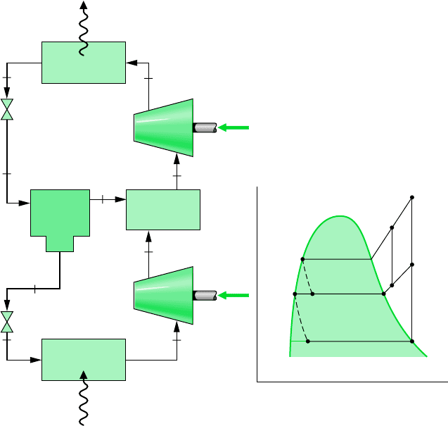
compressor work input. One arrangement for two-stage compression using the refrigerant
itself for intercooling is shown in Fig. 10.8. The principal states of the refrigerant for an ideal
cycle are shown on the accompanying T–s diagram.
468 Chapter 10 Refrigeration and Heat Pump Systems
Compressor
Compressor
W
c2
·
W
c1
·
Q
in
·
Q
out
·
Condenser
Evaporator
Direct contact
heat exchanger
Flash
chamber
Expansion
valve
Expansion
valve
5
6
8
7
9
4
3
1
2
(1)
(1)
(x)
(1)
(1 – x)
(1 – x)
(1 – x)
T
s
5
7
69
3
2
4
a
81
Figure 10.8
Refrigeration cycle with two stages of compression and flash
intercooling.

10.5 Absorption Refrigeration 469
Intercooling is accomplished in this cycle by means of a direct contact heat exchanger.
Relatively low-temperature saturated vapor enters the heat exchanger at state 9, where it
mixes with higher-temperature refrigerant leaving the first compression stage at state 2. A
single mixed stream exits the heat exchanger at an intermediate temperature at state 3 and is
compressed in the second compressor stage to the condenser pressure at state 4. Less work
is required per unit of mass flow for compression from 1 to 2 followed by compression from
3 to 4 than for a single stage of compression 1–2–a. Since the refrigerant temperature en-
tering the condenser at state 4 is lower than for a single stage of compression in which the
refrigerant would enter the condenser at state a, the external irreversibility associated with
heat transfer in the condenser is also reduced.
A central role is played in the cycle of Fig. 10.8 by a liquid–vapor separator, called a flash
chamber. Refrigerant exiting the condenser at state 5 expands through a valve and enters the
flash chamber at state 6 as a two-phase liquid–vapor mixture with quality x. In the flash
chamber, the liquid and vapor components separate into two streams. Saturated vapor exit-
ing the flash chamber enters the heat exchanger at state 9, where intercooling is achieved as
discussed above. Saturated liquid exiting the flash chamber at state 7 expands through a sec-
ond valve into the evaporator. On the basis of a unit of mass flowing through the condenser,
the fraction of the vapor formed in the flash chamber equals the quality x of the refrigerant
at state 6. The fraction of the liquid formed is then (1 x). The fractions of the total flow
at various locations are shown in parentheses on Fig. 10.8.
10.5 Absorption Refrigeration
Absorption refrigeration cycles are the subject of this section. These cycles have some fea-
tures in common with the vapor-compression cycles considered previously but differ in two
important respects:
One is the nature of the compression process. Instead of compressing a vapor between
the evaporator and the condenser, the refrigerant of an absorption system is absorbed
by a secondary substance, called an absorbent, to form a liquid solution. The liquid
solution is then pumped to the higher pressure. Because the average specific volume of
the liquid solution is much less than that of the refrigerant vapor, significantly less work
is required (see the discussion of Eq. 6.53b in Sec. 6.9). Accordingly, absorption
refrigeration systems have the advantage of relatively small work input compared
to vapor-compression systems.
The other main difference between absorption and vapor-compression systems is that
some means must be introduced in absorption systems to retrieve the refrigerant vapor
from the liquid solution before the refrigerant enters the condenser. This involves heat
transfer from a relatively high-temperature source. Steam or waste heat that otherwise
would be discharged to the surroundings without use is particularly economical for this
purpose. Natural gas or some other fuel can be burned to provide the heat source, and
there have been practical applications of absorption refrigeration using alternative
energy sources such as solar and geothermal energy.
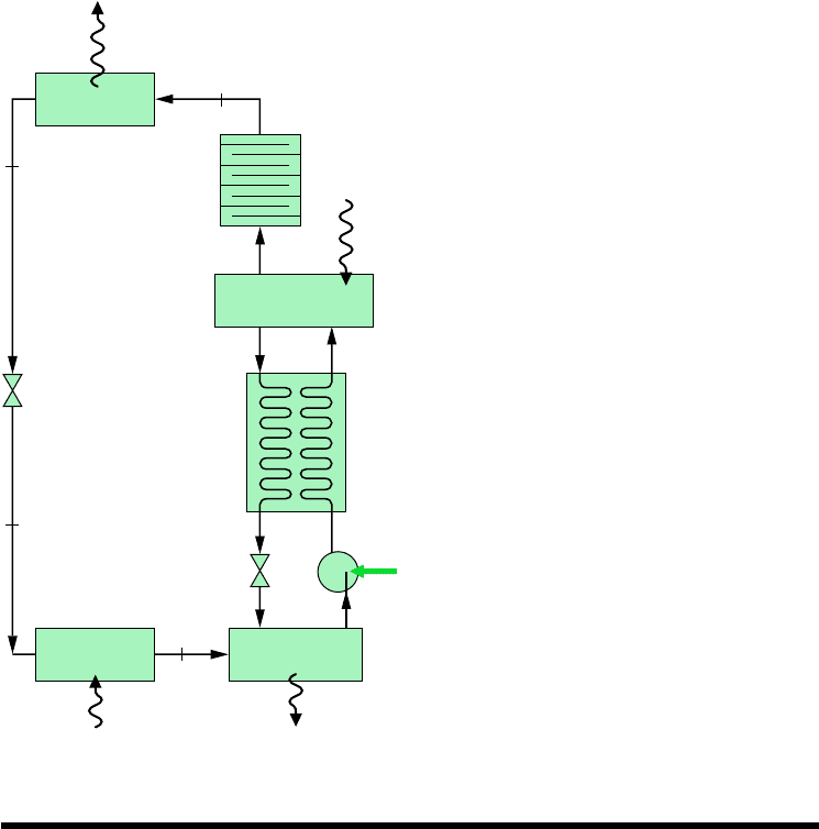
The principal components of an absorption refrigeration system are shown schematically
in Fig. 10.9. In this case, ammonia is the refrigerant and water is the absorbent. Ammonia
circulates through the condenser, expansion valve, and evaporator as in a vapor-compression
system. However, the compressor is replaced by the absorber, pump, generator, and valve
shown on the right side of the diagram.
In the absorber, ammonia vapor coming from the evaporator at state 1 is absorbed by
liquid water. The formation of this liquid solution is exothermic. Since the amount of
flash chamber
absorption refrigeration
absorber
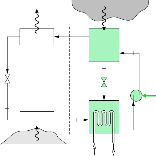
ammonia that can be dissolved in water increases as the solution temperature decreases,
cooling water is circulated around the absorber to remove the energy released as ammo-
nia goes into solution and maintain the temperature in the absorber as low as possible.
The strong ammonia–water solution leaves the absorber at point a and enters the pump,
where its pressure is increased to that of the generator.
In the generator, heat transfer from a high-temperature source drives ammonia vapor
out of the solution (an endothermic process), leaving a weak ammonia–water solution in
the generator. The vapor liberated passes to the condenser at state 2, and the remaining
weak solution at c flows back to the absorber through a valve. The only work input is
the power required to operate the pump, and this is small in comparison to the work
that would be required to compress refrigerant vapor between the same pressure levels.
However, costs associated with the heat source and extra equipment not required by
vapor-compressor systems can cancel the advantage of a smaller work input.
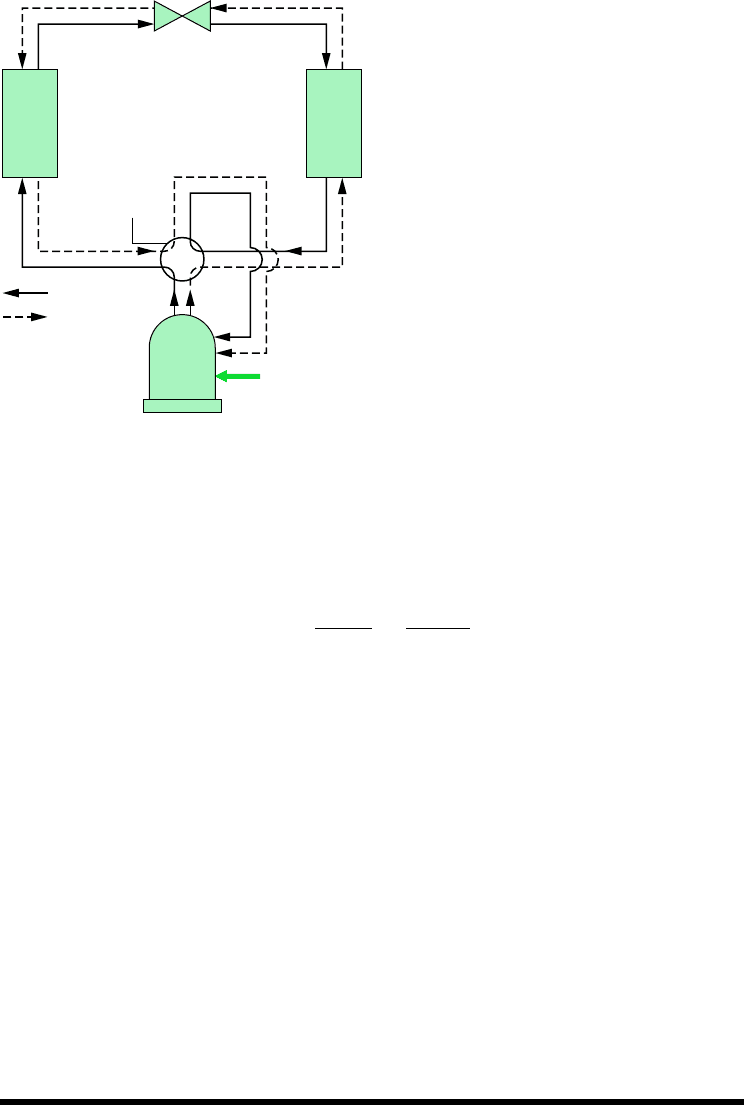
Ammonia–water systems normally employ several modifications of the simple absorption
cycle considered above. Two common modifications are illustrated in Fig. 10.10. In this cy-
cle, a heat exchanger is included between the generator and the absorber that allows the
strong water–ammonia solution entering the generator to be preheated by the weak solution
returning from the generator to the absorber, thereby reducing the heat transfer to the gen-
erator, The other modification shown on the figure is the rectifier placed between the
generator and the condenser. The function of the rectifier is to remove any traces of water
from the refrigerant before it enters the condenser. This eliminates the possibility of ice
formation in the expansion valve and the evaporator.
Another type of absorption system uses lithium bromide as the absorbent and water as the
refrigerant. The basic principle of operation is the same as for ammonia–water systems. To
achieve refrigeration at lower temperatures than are possible with water as the refrigerant, a
lithium bromide–water absorption system may be combined with another cycle using a re-
frigerant with good low-temperature characteristics, such as ammonia, to form a cascade
refrigeration system.
Q
#
G
.
470 Chapter 10 Refrigeration and Heat Pump Systems
W
p
·
b
c
a
1
3
2
4
Expansion
valve
Evaporator
Condenser
High-
temperature
source
Generator
Weak solution
Strong solution
Absorber
Valve
Pump
Refrigerated
region
Cooling
water
Q
out
·
Q
in
·
Q
G
·
Figure 10.9 Simple
ammonia–water absorption
refrigeration system.
generator
rectifier
10.6 Heat Pump Systems 471
The objective of a heat pump is to maintain the temperature within a dwelling or other building
above the temperature of the surroundings or to provide a heat transfer for certain industrial
processes that occur at elevated temperatures. Heat pump systems have many features in
common with the refrigeration systems considered thus far and may be of the vapor-
compression or absorption type. Vapor-compression heat pumps are well suited for space
heating applications and are commonly used for this purpose. Absorption heat pumps
have been developed for industrial applications and are also increasingly being used for space
heating. To introduce some aspects of heat pump operation, let us begin by considering
the Carnot heat pump cycle.
CARNOT HEAT PUMP CYCLE
By simply changing our viewpoint, we can regard the cycle shown in Fig. 10.1 as a heat
pump. The objective of the cycle now, however, is to deliver the heat transfer to the warm
region, which is the space to be heated. At steady state, the rate at which energy is supplied
to the warm region by heat transfer is the sum of the energy supplied to the working fluid
from the cold region, and the net rate of work input to the cycle, That is
(10.8)
Q
#
out
Q
#
in
W
#
net
W
#
net
.Q
#
in
,
Q
#
out
Condenser
Expansion
valve
Evaporator Absorber
Valve
Pump
Heat
exchanger
Generator
Rectifier
3
2
4
1
Q
in
·
Q
out
·
Q
G
·
Q
cw
·
W
p
·
Figure 10.10 Modified ammonia–water
absorption system.
10.6 Heat Pump Systems

The coefficient of performance of any heat pump cycle is defined as the ratio of the heat-
ing effect to the net work required to achieve that effect. For the Carnot heat pump cycle of
Fig. 10.1
(10.9)
This equation, which corresponds to Eq. 5.10, represents the maximum theoretical coefficient
of performance for any heat pump cycle operation between two regions at temperatures T
C
and T
H
. Actual heat pump systems have coefficients of performance that are lower than would
be calculated from Eq. 10.9.
A study of Eq. 10.9 shows that as the temperature T
C
of the cold region decreases, the co-
efficient of performance of the Carnot heat pump decreases. This trait is also exhibited by ac-
tual heat pump systems and suggests why heat pumps in which the role of the cold region is
played by the local atmosphere (air-source heat pumps) normally require backup systems to
provide heating on days when the ambient temperature becomes very low. If sources such as
well water or the ground itself are used, relatively high coefficients of performance can be
achieve despite low ambient air temperatures, and backup systems may not be required.
VAPOR-COMPRESSION HEAT PUMPS
Actual heat pump systems depart significantly from the Carnot cycle model. Most systems
in common use today are of the vapor-compression type. The method of analysis of vapor-
compression heat pumps is the same as that of vapor-compression refrigeration cycles con-
sidered previously. Also, the previous discussions concerning the departure of actual systems
from ideality apply for vapor-compression heat pump systems as for vapor-compression
refrigeration cycles.
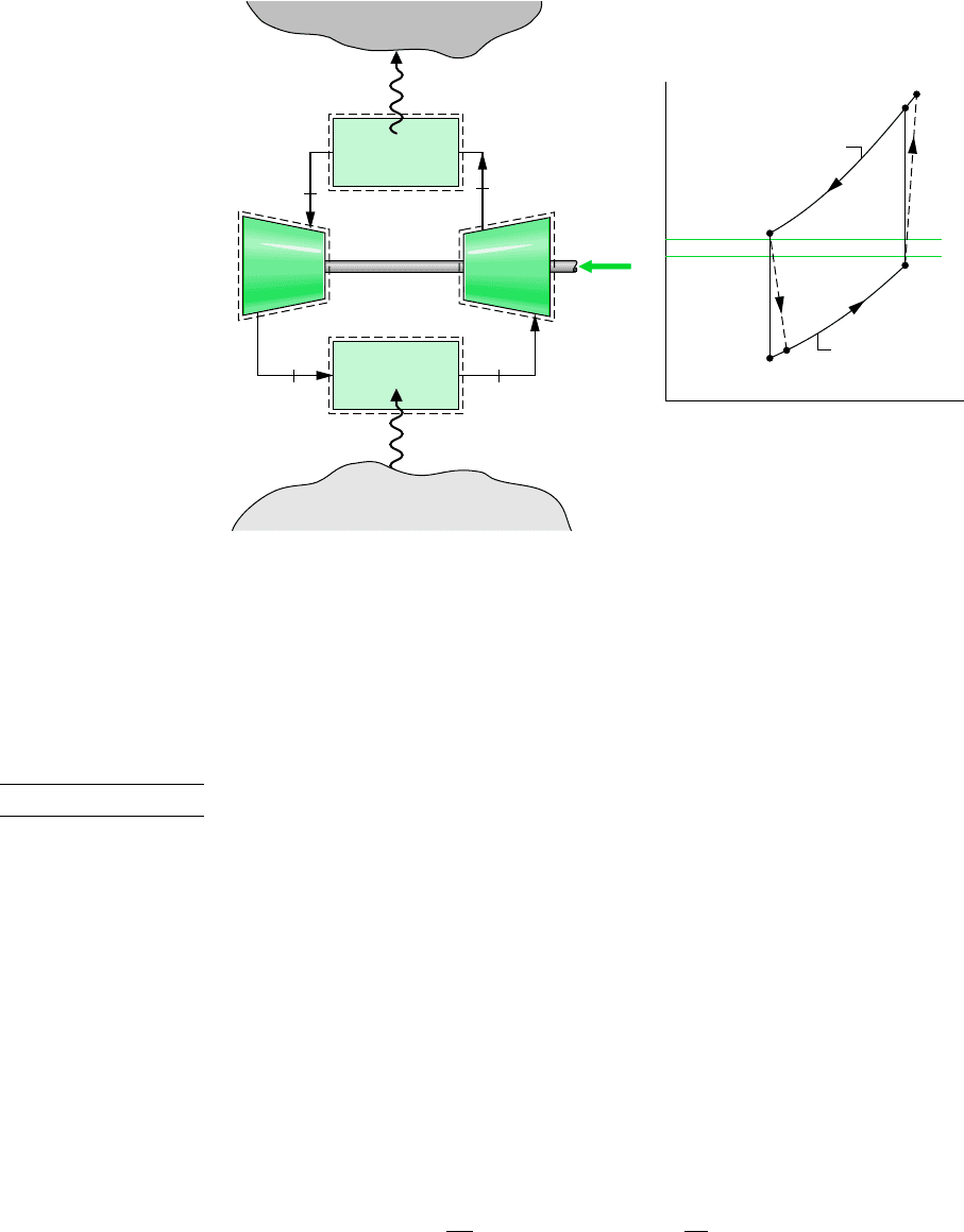
As illustrated by Fig. 10.11, a typical vapor-compression heat pump for space heating
has the same basic components as the vapor-compression refrigeration system: compressor,
T
H
1s
a
s
b
2
1T
H
T
C
21s
a
s
b
2
T
H
T
H
T
C
area 2–a–b–3–2
area 1–2–3–4–1
g
max
Q
#
out
m
#
W
#
c
m
#
W
#
t
m
#
472 Chapter 10 Refrigeration and Heat Pump Systems
Inside
air
Outside
air
Condenser
Compressor
Evaporator
W
c
·
Q
in
·
21
43
Q
out
·
Expansion
valve
Figure 10.11 Air-source vapor-compression heat pump system.
vapor-compression
heat pump
10.7 Gas Refrigeration Systems 473
condenser, expansion valve, and evaporator. The objective of the system is different, how-
ever. In a heat pump system, comes from the surroundings, and is directed to the
dwelling as the desired effect. A net work input is required to accomplish this effect.
The coefficient of performance of a simple vapor-compression heat pump with states as
designated on Fig. 10.11 is
(10.10)
The value of can never be less than unity.
Many possible sources are available for heat transfer to the refrigerant passing through
the evaporator. These include the outside air, the ground, and lake, river, or well water. Liq-
uid circulated through a solar collector and stored in an insulated tank also can be used as a
source for a heat pump. Industrial heat pumps employ waste heat or warm liquid or gas
streams as the low-temperature source and are capable of achieving relatively high condenser
temperatures.
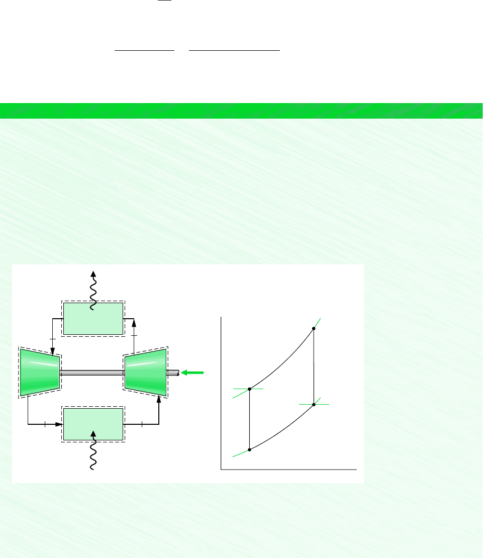
In the most common type of vapor-compression heat pump for space heating, the evapo-
rator communicates thermally with the outside air. Such air-source heat pumps also can be
used to provide cooling in the summer with the use of a reversing valve, as illustrated in
Fig. 10.12. The solid lines show the flow path of the refrigerant in the heating mode, as de-
scribed previously. To use the same components as an air conditioner, the valve is actuated,
and the refrigerant follows the path indicated by the dashed line. In the cooling mode, the
outside heat exchanger becomes the condenser, and the inside heat exchanger becomes the
evaporator. Although heat pumps can be more costly to install and operate than other direct
heating systems, they can be competitive when the potential for dual use is considered.
g
Q
#
out
m
#
W
#
c
m
#
h
2
h
3
h
2
h
1
Q
#
out
Q
#
in
Expansion
valve
Outside
heat exchanger
Inside
heat exchanger
Reversing
valve
Compressor
Heating mode
Cooling mode
W
c
·
Figure 10.12 Example of an air-to-air
reversing heat pump.
10.7 Gas Refrigeration Systems
All refrigeration systems considered thus far involve changes in phase. Let us now turn to
gas refrigeration systems in which the working fluid remains a gas throughout. Gas refrig-
eration systems have a number of important applications. They are used to achieve very low
temperatures for the liquefaction of air and other gases and for other specialized applications
air-source heat pump
gas refrigeration systems
474 Chapter 10 Refrigeration and Heat Pump Systems
such as aircraft cabin cooling. The Brayton refrigeration cycle illustrates an important type
of gas refrigeration system.
BRAYTON REFRIGERATION CYCLE
The Brayton refrigeration cycle is the reverse of the closed Brayton power cycle introduced
in Sec. 9.6. A schematic of the reversed Brayton cycle is provided in Fig. 10.13a. The re-
frigerant gas, which may be air, enters the compressor at state 1, where the temperature is
somewhat below the temperature of the cold region, T
C
, and is compressed to state 2. The
gas is then cooled to state 3, where the gas temperature approaches the temperature of the
warm region, T
H
. Next, the gas is expanded to state 4, where the temperature, T
4
, is well be-
low that of the cold region. Refrigeration is achieved through heat transfer from the cold re-
gion to the gas as it passes from state 4 to state 1, completing the cycle. The T–s diagram in
Fig. 10.13b shows an ideal Brayton refrigeration cycle, denoted by 1–2s–3–4s–1, in which
all processes are assumed to be internally reversible and the processes in the turbine and
compressor are adiabatic. Also shown is the cycle 1–2–3–4–1, which suggests the effects of
irreversibilities during adiabatic compression and expansion. Frictional pressure drops have
been ignored.
CYCLE ANALYSIS. The method of analysis of the Brayton refrigeration cycle is similar to
that of the Brayton power cycle. Thus, at steady state the work of the compressor and the
turbine per unit of mass flow are, respectively
In obtaining these expressions, heat transfer with the surroundings and changes in kinetic and
potential energy have been ignored. In contrast to the vapor-compression cycle of Fig. 10.2,
W
#
c
m
#
h
2
h
1
and
W
#
t
m
#
h
3
h
4
41
3
2
Heat exchanger
Heat exchanger
Turbine Compressor
Q
out
·
Q
in
·
W
cycle
=
W
c
– W
t
·
··
Warm region
at T
H
Cold region
at T
C
(a)
Constant pressure
Constant pressure
T
H
T
C
4s
4
3
2s
2
1
T
s
(b)
Figure 10.13
Brayton refrigeration cycle.
Brayton refrigeration
cycle
10.7 Gas Refrigeration Systems 475
the work developed by the turbine of a Brayton refrigeration cycle is significant relative to
the compressor work input.
The heat transfer from the cold region to the refrigerant gas circulating through the low-
pressure heat exchanger, the refrigeration effect, is
The coefficient of performance is the ratio of the refrigeration effect to the net work input:
(10.11)
In the next example, we illustrate the analysis of an ideal Brayton refrigeration cycle.
b
Q
#
in
m
#
W
#
c
m
#
W
#
t
m
#
1h
1
h
4
2
1h
2
h
1
2 1h
3
h
4
2
Q
#
in
m
#
h
1
h
4
EXAMPLE 10.4 Ideal Brayton Refrigeration Cycle
Air enters the compressor of an ideal Brayton refrigeration cycle at 1 bar, 270K, with a volumetric flow rate of 1.4 m
3
/s. If
the compressor pressure ratio is 3 and the turbine inlet temperature is 300K, determine (a) the net power input, in kW,
(b) the refrigeration capacity, in kW, (c) the coefficient of performance.
SOLUTION
Known: An ideal Brayton refrigeration cycle operates with air. Compressor inlet conditions, the turbine inlet temperature,
and the compressor pressure ratio are given.
Find: Determine the net power input, in kW, the refrigeration capacity, in kW, and the coefficient of performance.
Schematic and Given Data:
T
3
=
300K
T
1
=
270K
2s
4s
p = 3 bars
p = 1 bar
s
T
3
1
4s 1
3
2s
Heat exchanger
Heat exchanger
Turbine Compressor
Q
out
·
Q
in
·
W
cycle
·
T
3
=
300K
(AV)
1
=
T
1
=
p
1
=
1.4 m
3
/s
270K
1 bar
Figure E10.4
Assumptions:
1. Each component of the cycle is analyzed as a control volume at steady state. The control volumes are indicated by dashed
lines on the accompanying sketch.
2. The turbine and compressor processes are isentropic.
