Moran M.J., Shapiro H.N. Fundamentals of Engineering Thermodynamics
Подождите немного. Документ загружается.


406 Chapter 9 Gas Power Systems
9.8.2 Compression with Intercooling
The net work output of a gas turbine also can be increased by reducing the compressor work
input. This can be accomplished by means of multistage compression with intercooling. The
present discussion provides an introduction to this subject.
Let us first consider the work input to compressors at steady state, assuming that irre-
versibilities are absent and changes in kinetic and potential energy from inlet to exit are
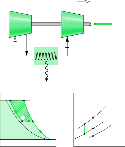
negligible. The p–v diagram of Fig. 9.17 shows two possible compression paths from a
specified state 1 to a specified final pressure p
2
. Path 1–2 is for an adiabatic compression.
Path 1–2 corresponds to a compression with heat transfer from the working fluid to the sur-
roundings. The area to the left of each curve equals the magnitude of the work per unit mass
of the respective process (see Sec. 6.9). The smaller area to the left of Process 1–2 indi-
cates that the work of this process is less than for the adiabatic compression from 1 to 2.
This suggests that cooling a gas during compression is advantageous in terms of the work-
input requirement.
Although cooling a gas as it is compressed would reduce the work, a heat transfer rate
high enough to effect a significant reduction in work is difficult to achieve in practice. A
practical alternative is to separate the work and heat interactions into separate processes
by letting compression take place in stages with heat exchangers, called intercoolers, cool-
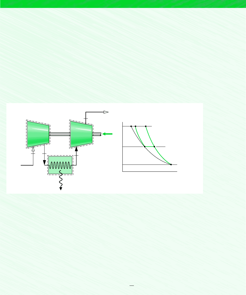
ing the gas between stages. Figure 9.18 illustrates a two-stage compressor with an
The thermal efficiency calculation must take into account the compressor work, the work of each turbine, and the total
heat added. Thus, on a unit mass basis
Comparing the present value with the thermal efficiency determined in part (a) of Example 9.4, we can conclude that the
use of reheat coupled with regeneration can result in a substantial increase in thermal efficiency.
0.654 165.4% 2
11515.4 1095.92 11515.4 1127.62 1579.9 300.192
11515.4 1127.62 11515.4 1095.92
h
1h
3
h
a
2 1h
b
h
4
2 1h
2
h
1
2
1h
3
h
x
2 1h
b
h
a
2
❶
❶
p
v
2
Adiabatic compression
2′
Compression with cooling
int
rev
=
∫
vdp
W
·
c
___
m
·
2
1
p
2
p
1
T
1
Figure 9.17 Internally reversible compres-
sion processes between two fixed pressures.
intercooler
9.8 Regenerative Gas Turbines with Reheat and Intercooling 407
p
v
T
s
22′
2′
2
d
c
a
b
c
1
1
p
i
p
i
p
2
p
1
s = c
T = c
c
d
Compressor
stage 1
Compressor
stage 2
W
·
c
1
2
Intercooler
Q
·
out
d
Figure 9.18
Two-stage
compression with intercooling.
intercooler. The accompanying p–v and T–s diagrams show the states for internally
reversible processes:
Process 1– c is an isentropic compression from state 1 to state c where the pressure
is p
i
.
Process c–d is constant-pressure cooling from temperature T
c
to T
d
.
Process d–2 is an isentropic compression to state 2.
The work input per unit of mass flow is represented on the p–v diagram by shaded area
1–c–d–2–a–b–1. Without intercooling the gas would be compressed isentropically in a sin-
gle stage from state 1 to state 2 and the work would be represented by enclosed area
1–2–a–b–1. The crosshatched area on the p–v diagram represents the reduction in work that
would be achieved with intercooling.
Some large compressors have several stages of compression with intercooling between
stages. The determination of the number of stages and the conditions at which to operate
the various intercoolers is a problem in optimization. The use of multistage compression
with intercooling in a gas turbine power plant increases the net work developed by reduc-
ing the compression work. By itself, though, compression with intercooling would not nec-
essarily increase the thermal efficiency of a gas turbine because the temperature of the air
entering the combustor would be reduced (compare temperatures at states 2 and 2 on the
T–s diagram of Fig. 9.18). A lower temperature at the combustor inlet would require addi-
tional heat transfer to achieve the desired turbine inlet temperature. The lower temperature
at the compressor exit enhances the potential for regeneration, however, so when intercooling
is used in conjunction with regeneration, an appreciable increase in thermal efficiency can
result.
408 Chapter 9 Gas Power Systems
EXAMPLE 9.9 Compression with Intercooling
Air is compressed from 100 kPa, 300 K to 1000 kPa in a two-stage compressor with intercooling between stages. The inter-
cooler pressure is 300 kPa. The air is cooled back to 300 K in the intercooler before entering the second compressor stage.
Each compressor stage is isentropic. For steady-state operation and negligible changes in kinetic and potential energy from
inlet to exit, determine (a) the temperature at the exit of the second compressor stage and (b) the total compressor work input
per unit of mass flow. (c) Repeat for a single stage of compression from the given inlet state to the final pressure.
SOLUTION
Known: Air is compressed at steady state in a two-stage compressor with intercooling between stages. Operating pressures
and temperatures are given.
Find: Determine the temperature at the exit of the second compressor stage and the total work input per unit of mass flow.
Repeat for a single stage of compression.
Schematic and Given Data:
p
v
23
cd
1
p
i
= 300 kPa
c
d
Compressor
stage 1
Compressor
stage 2
W
·
c
1
2
Intercooler
Q
·
out
p
1
= 100 kPa
T
1
= 300 K
p
2
= 1000 kPa
T
1
= 300 K
p
1
= 100 kPa
T
d
= 300 K
p
2
= 1000 kPa
Figure E9.9
In the next example, we analyze a two-stage compressor with intercooling between the
stages. Results are compared with those for a single stage of compression.
Assumptions:
1. The compressor stages and intercooler are analyzed as control volumes at steady state. The control volumes are shown on
the accompanying sketch by dashed lines.
2. The compression processes are isentropic.
3. There is no pressure drop for flow through the intercooler.
4. Kinetic and potential energy effects are negligible.
5. The air is modeled as an ideal gas.
Analysis:
(a) The temperature at the exit of the second compressor stage, T
2
, can be found using the following relationship for the isen-
tropic process d–2
p
r2
p
r d
p
2
p
d

9.8 Regenerative Gas Turbines with Reheat and Intercooling 409
EXAMPLE 9.10 Intercooler Pressure for Minimum Compressor Work
If the inlet state and the exit pressure are specified for a two-stage compressor operating at steady state, show that the mini-
mum total work input is required when the pressure ratio is the same across each stage. Use a cold air-standard analysis
assuming that each compression process is isentropic, there is no pressure drop through the intercooler, and the temperature
at the inlet to each compressor stage is the same. Kinetic and potential energy effects can be ignored.
With p
rd
at T
d
300 K from Table A-22, p
2
1000 kPa, and p
d
300 kPa,
Interpolating in Table A-22, we get T
2
422 K and h
2
423.8 kJ/kg
(b) The total compressor work input per unit of mass is the sum of the work inputs for the two stages. That is
From Table A-22 at T
1
300 K, h
1
300.19 kJ/kg. Since T
d
T
1
, h
d
300.19 kJ/kg. To find h
c
, use p
r
data from
Table A-22 together with p
1
100 kPa and p
c
300 kPa to write
Interpolating in Table A-22, we obtain h
c
411.3 kJ/kg. Hence, the total compressor work per unit of mass is
(c) For a single isentropic stage of compression, the exit state would be state 3 located on the accompanying p–v diagram.
The temperature at this state can be determined using
Interpolating in Table A-22, we get T
3
574 K and h
3
579.9 kJ/kg.
The work input for a single stage of compression is then
This calculation confirms that a smaller work input is required with two-stage compression and intercooling than with a single
stage of compression. With intercooling, however, a much lower gas temperature is achieved at the compressor exit.
W
#
c
m
#
h
3
h
1
579.9 300.19 279.7 kJ/kg
p
r3
p
r1
p
3
p
1
11.3862
1000
100
13.86
W
#
c
m
#
1411.3 300.192 1423.8 300.192 234.7 kJ/kg
p
r c
p
r1
p
c
p
1
11.3862
300
100
4.158
W
#
c
m
#
1h
c
h
1
2 1h
2
h
d
2
p
r2
11.3862
1000
300
4.62
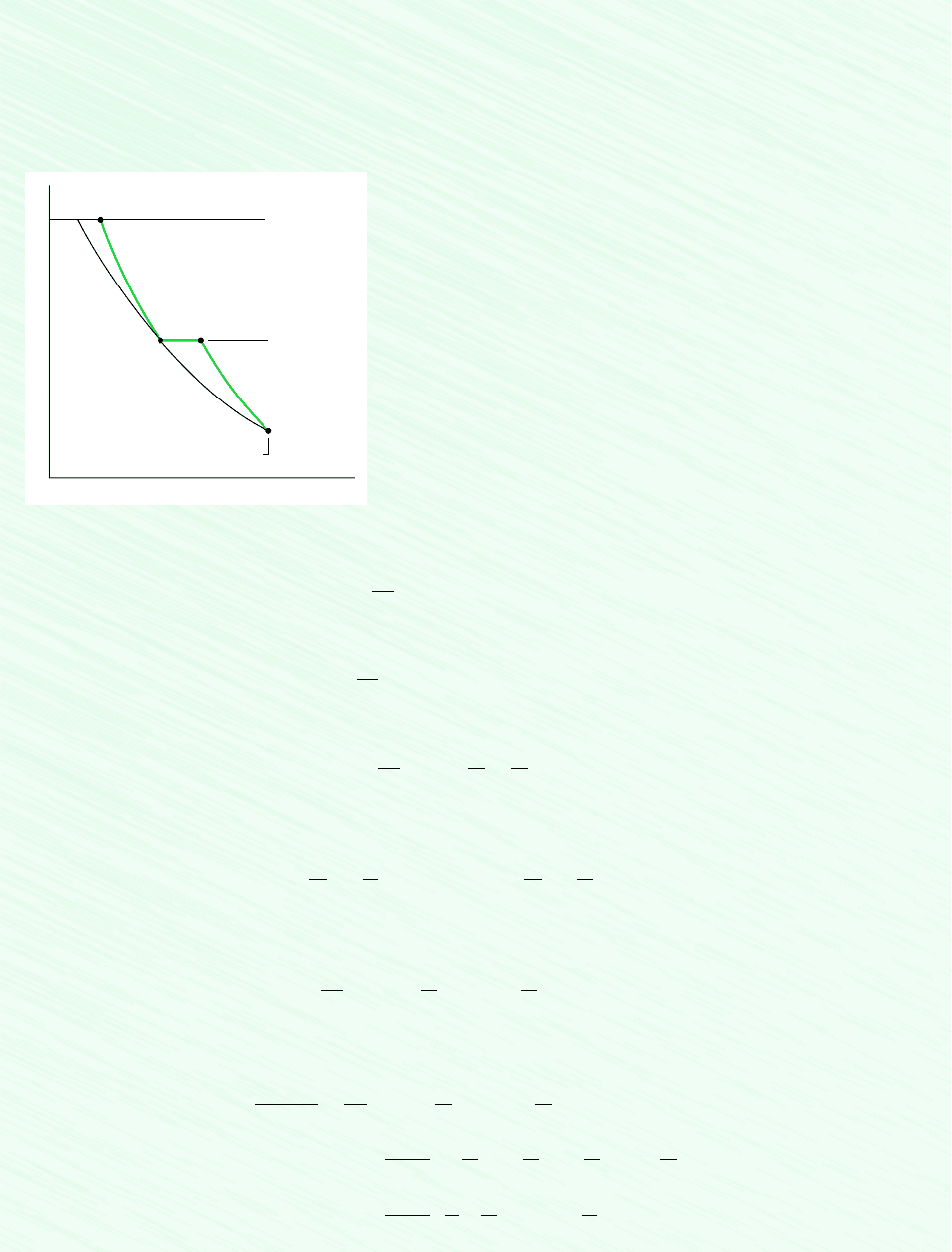
Referring again to Fig. 9.18, the size of the crosshatched area on the p–v diagram repre-
senting the reduction in work with intercooling depends on both the temperature T
d
at the
exit of the intercooler and the intercooler pressure p
i
. By properly selecting T
d
and p
i
,the
total work input to the compressor can be minimized. For example, if the pressure p
i
is spec-
ified, the work input would decrease (crosshatched area would increase) as the temperature
T
d
approaches T
1
, the temperature at the inlet to the compressor. For air entering the com-
pressor from the surroundings, T
1
would be the limiting temperature that could be achieved
at state d through heat transfer with the surroundings only. Also, for a specified value of the
temperature T
d
, the pressure p
i
can be selected so that the total work input is a minimum
(crosshatched area is a maximum).
Example 9.10 provides an illustration of the determination of the intercooler pressure for
minimum total work using a cold air-standard analysis.
410 Chapter 9 Gas Power Systems
SOLUTION
Known: A two-stage compressor with intercooling operates at steady state under specified conditions.
Find: Show that the minimum total work input is required when the pressure ratio is the same across each stage.
Schematic and Given Data:
p
v
2
c
d
1
p
i
variable
Compressor inlet state specified
s =
c
s = c
T = c
p
2
specified
Figure E9.10
Assumptions:
1. The compressor stages and intercooler are analyzed as control volumes
at steady state.
2. The compression processes are isentropic.
3. There is no pressure drop for flow through the intercooler.
4. The temperature at the inlet to both compressor stages is the same.
5. Kinetic and potential energy effects are negligible.
6. The working fluid is air modeled as an ideal gas.
7. The specific heat c
p
and the specific heat ratio k are constant.
Analysis: The total compressor work input per unit of mass flow is
Since c
p
is constant
With T
d
T
1
(assumption 4), this becomes on rearrangement
Since the compression processes are isentropic and the specific heat ratio k is constant, the pressure and temperature ratios
across the compressor stages are related, respectively, by
In the second of these equations, T
d
T
1
by assumption 4.
Collecting results
Hence, for specified values of T
1
, p
1
, p
2
, and c
p
, the value of the total compressor work input varies with the intercooler pres-
sure only. To determine the pressure p
i
that minimizes the total work, form the derivative
c
p
T
1
a
k 1
k
b
1
p
i
ca
p
i
p
1
b
1k 12
k
a
p
2
p
i
b
1k 12
k
d
c
p
T
1
a
k 1
k
b
ca
p
i
p
1
b
1
k
a
1
p
1
b a
p
2
p
i
b
1
k
a
p
2
p
2
i
bd
0 1W
#
c
m
#
2
0p
i
0
0p
i
ec
p
T
1
ca
p
i
p
1
b
1k 12
k
a
p
2
p
i
b
1k 12
k
2 df
W
#
c
m
#
c
p
T
1
ca
p
i
p
1
b
1k 12
k
a
p
2
p
i
b
1k 12
k
2 d
T
c
T
1
a
p
i
p
1
b
1k 12
k
and
T
2
T
d
a
p
2
p
i
b
1k 12
k
W
#
c
m
#
c
p
T
1
a
T
c
T
1
T
2
T
1
2b
W
#
c
m
#
c
p
1T
c
T
1
2 c
p
1T
2
T
d
2
W
#
c
m
#
1h
c
h
1
2 1h
2
h
d
2
9.8 Regenerative Gas Turbines with Reheat and Intercooling 411
When the partial derivative is set to zero, the desired relationship is obtained
By checking the sign of the second derivative, it can be verified that the total compressor work is a minimum.
This relationship is for a two-stage compressor. Appropriate relations can be obtained similarly for multistage compressors.
p
i
p
1
p
2
p
i
❶
❶
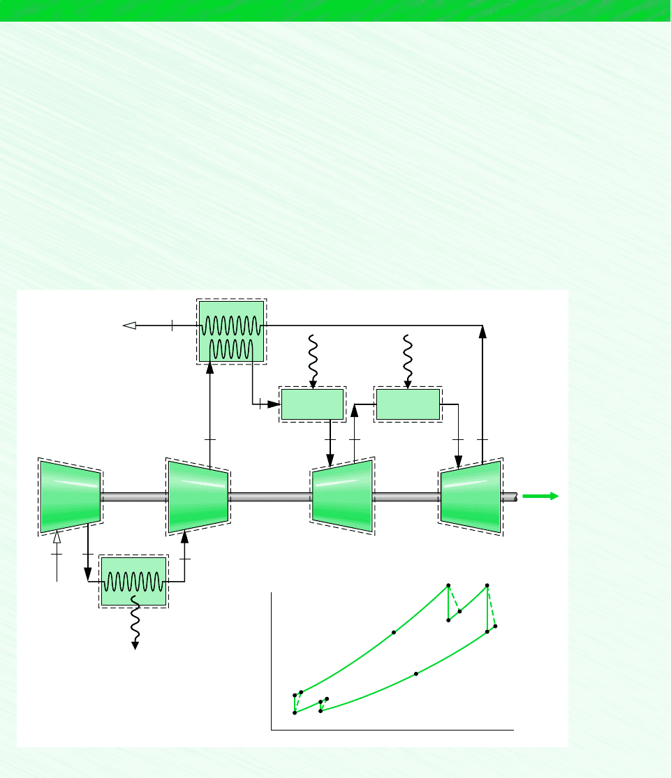
9.8.3 Reheat and Intercooling
Reheat between turbine stages and intercooling between compressor stages provide two im-
portant advantages: The net work output is increased, and the potential for regeneration is
enhanced. Accordingly, when reheat and intercooling are used together with regeneration,
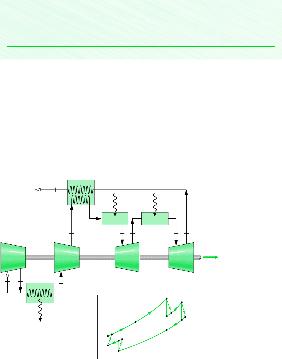
a substantial improvement in performance can be realized. One arrangement incorporating
reheat, intercooling, and regeneration is shown in Fig. 9.19. This gas turbine has two stages
of compression and two turbine stages. The accompanying T–s diagram is drawn to indi-
cate irreversibilities in the compressor and turbine stages. The pressure drops that would
occur as the working fluid passes through the intercooler, regenerator, and combustors are
not shown.
2
3
Compressor
1
Compressor
2
W
·
cycle
1
Intercooler
Q
·
out
Turbine
2
Turbine
1
Combustor 1
5
467 9
10
Regenerator
Q
·
in,
1
Combustor 2
8
Q
·
in,
2
T
s
1
3
4
5
6
8
9s
7s
10
9
7
4s
2s
2
Figure 9.19 Regenerative gas turbine with intercooling and reheat.
412 Chapter 9 Gas Power Systems
Example 9.11 illustrates the analysis of a regenerative gas turbine with intercooling and
reheat.
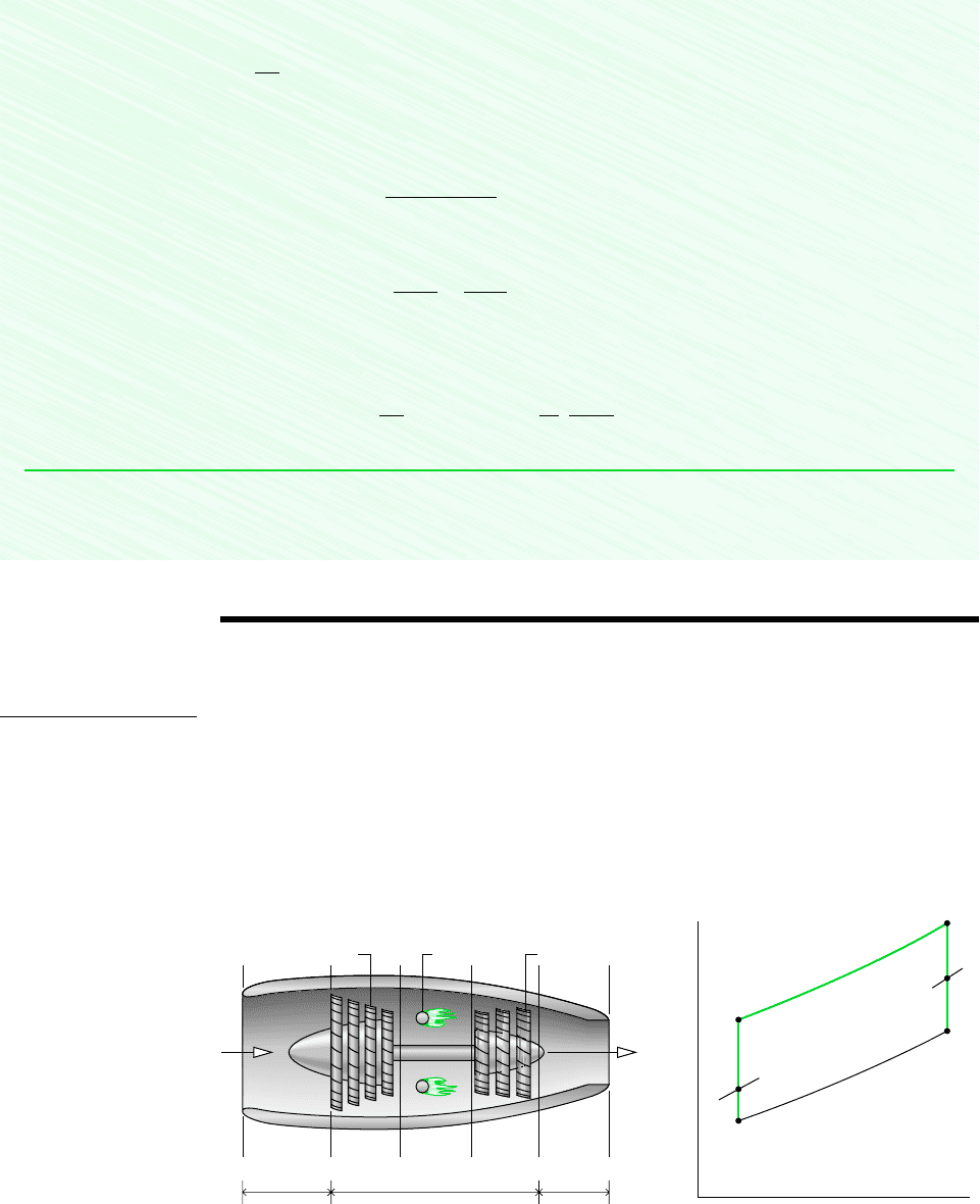
EXAMPLE 9.11 Regenerative Gas Turbine with Intercooling and Reheat
A regenerative gas turbine with intercooling and reheat operates at steady state. Air enters the compressor at 100 kPa, 300 K
with a mass flow rate of 5.807 kg/s. The pressure ratio across the two-stage compressor is 10. The pressure ratio across the
two-stage turbine is also 10. The intercooler and reheater each operate at 300 kPa. At the inlets to the turbine stages, the tem-
perature is 1400 K. The temperature at the inlet to the second compressor stage is 300 K. The isentropic efficiency of each
compressor and turbine stage is 80%. The regenerator effectiveness is 80%. Determine
(a) the thermal efficiency, (b) the back
work ratio,
(c) the net power developed, in kW.
SOLUTION
Known: An air-standard regenerative gas turbine with intercooling and reheat operates at steady state. Operating pressures
and temperatures are specified. Turbine and compressor isentropic efficiencies are given and the regenerator effectiveness is
known.
Find: Determine the thermal efficiency, back work ratio, and net power developed, in kW.
Schematic and Given Data:
2
3
Compressor
1
Compressor
2
W
·
cycle
1
Intercooler
Q
·
out
Turbine
2
Turbine
1
Combustor
5
467 9
10
Regenerator
Q
·
in,
1
Reheat
combustor
8
Q
·
in,
2
T
s
1
3
4
5
6
8
9s
7s
10
9
7
4s
2s
2
T
1
= 300 K
p
1
= 100 kPa
m
·
= 5.807 kg/s
p
2
= p
3
= 300 kPa
p
4
= p
5
= p
6
=
1000 kPa
T
6
= T
8
= 1400 K p
7
= p
8
= 300 kPa
Figure E9.11

9.8 Regenerative Gas Turbines with Reheat and Intercooling 413
Assumptions:
1. Each component is analyzed as a control volume at steady state. The control volumes are shown on the accompanying
sketch by dashed lines.
2. There are no pressure drops for flow through the heat exchangers.
3. The compressor and turbine are adiabatic.
4. Kinetic and potential energy effects are negligible.
5. The working fluid is air modeled as an ideal gas.
Analysis: We begin by listing the specific enthalpies at the principal states of this cycle. The enthalpies at states 1, 2s, 3,
and 4s are obtained from the solution to Example 9.9 where these states are designated as 1, c, d, and 2, respectively. Thus,
h
1
h
3
300.19 kJ/kg, h
2s
411.3 kJ/kg, h
4s
423.8 kJ/kg.
The specific enthalpies at states 6, 7s, 8, and 9s are obtained from the solution to Example 9.8, where these states are des-
ignated as 3, a, b, and 4, respectively. Thus, h
6
h
8
1515.4 kJ/kg, h
7s
1095.9 kJ/kg, h
9s
1127.6 kJ/kg.
The specific enthalpy at state 4 can be determined using the isentropic efficiency of the second compressor stage
Solving for h
4
Similarly, the specific enthalpy at state 2 is h
2
439.1 kJ/kg.
The specific enthalpy at state 9 can be determined using the isentropic efficiency of the second turbine stage
Solving for h
9
Similarly, the specific enthalpy at state 7 is h
7
1179.8 kJ/kg.
The specific enthalpy at state 5 can be determined using the regenerator effectiveness
Solving for h
5
(a) The thermal efficiency must take into account the work of both turbine stages, the work of both compressor stages, and
the total heat added. The total turbine work per unit of mass flow is
The total compressor work input per unit of mass flow is
1439.1 300.192 1454.7 300.192 293.4 kJ/kg
W
#
c
m
#
1h
2
h
1
2 1h
4
h
3
2
11515.4 1179.82 11515.4 1205.22 645.8 kJ/kg
W
#
t
m
#
1h
6
h
7
2 1h
8
h
9
2
1055.1 kJ/kg
h
5
h
4
h
reg
1h
9
h
4
2 454.7 0.811205.2 454.72
h
reg
h
5
h
4
h
9
h
4
1205.2 kJ/kg
h
9
h
8
h
t
1h
8
h
9s
2 1515.4 0.811515.4 1127.62
h
t
h
8
h
9
h
8
h
9s
454.7 kJ/kg
h
4
h
3
h
4s
h
3
h
c
300.19 a
423.8 300.19
0.8
b
h
c
h
4s
h
3
h
4
h
3
414 Chapter 9 Gas Power Systems
The total heat added per unit of mass flow is
Calculating the thermal efficiency
(b) The back work ratio is
(c) The net power developed is
Comparing the thermal efficiency, back work ratio, and net power values of the current example with the corresponding
values of Example 9.6, it should be evident that gas turbine power plant performance can be increased significantly by
coupling reheat and intercooling with regeneration.
a5.807
kg
s
b 1645.8 293.42
kJ
kg
`
1 kJ/s
1 kW
` 2046 kW
W
#
cycle
m
#
1W
#
t
m
#
W
#
c
m
#
2
bwr
W
#
c
m
#
W
#
t
m
#
293.4
645.8
0.454 145.4%2
h
645.8 293.4
795.9
0.443 144.3%2
11515.4 1055.12 11515.4 1179.82 795.9 kJ/kg
Q
#
in
m
#
1h
6
h
5
2 1h
8
h
7
2
❶
❶
9.9 Gas Turbines for Aircraft Propulsion
Gas turbines are particularly suited for aircraft propulsion because of their favorable power-
to-weight ratios. The turbojet engine is commonly used for this purpose. As illustrated in
Fig. 9.20, this type of engine consists of three main sections: the diffuser, the gas generator,
and the nozzle. The diffuser placed before the compressor decelerates the incoming air rel-
ative to the engine. A pressure rise known as the ram effect is associated with this deceler-
ation. The gas generator section consists of a compressor, combustor, and turbine, with the
same functions as the corresponding components of a stationary gas turbine power plant. In
a turbojet engine, the turbine power output need only be sufficient to drive the compressor
T
p = c
p = c
s
1
a
2
3
4
5
Compressor
Diffuser NozzleGas generator
(a)(b)
Combustors Turbine
Product
gases out
Air
in
a12345
Figure 9.20 Turbojet engine schematic and accompanying ideal T–s diagram.
turbojet engine
ram effect
9.9 Gas Turbines for Aircraft Propulsion 415
and auxiliary equipment, however. The gases leave the turbine at a pressure significantly
greater than atmospheric and expand through the nozzle to a high velocity before being dis-
charged to the surroundings. The overall change in the velocity of the gases relative to the
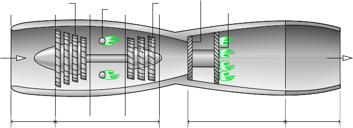
engine gives rise to the propulsive force, or thrust. Some turbojets are equipped with an
afterburner, as shown in Fig. 9.21. This is essentially a reheat device in which additional
fuel is injected into the gas exiting the turbine and burned, producing a higher temperature
at the nozzle inlet than would be achieved otherwise. As a consequence, a greater nozzle exit
velocity is attained, resulting in increased thrust.
TURBOJET ANALYSIS. The T–s diagram of the processes in an ideal turbojet engine is
shown in Fig. 9.20b. In accordance with the assumptions of an air-standard analysis, the
working fluid is air modeled as an ideal gas. The diffuser, compressor, turbine, and nozzle
processes are isentropic, and the combustor operates at constant pressure.
Process a–1 shows the pressure rise that occurs in the diffuser as the air decelerates
isentropically through this component.
Process 1–2 is an isentropic compression.
Process 2–3 is a constant-pressure heat addition.
Process 3–4 is an isentropic expansion through the turbine during which work is
developed.
Process 4–5 is an isentropic expansion through the nozzle in which the air accelerates
and the pressure decreases.
Owing to irreversibilities in an actual engine, there would be increases in specific entropy
across the diffuser, compressor, turbine, and nozzle. In addition, there would be a pressure
drop through the combustor of the actual engine. Further details regarding flow through noz-
zles and diffusers are provided in Secs. 9.13 and 9.14. The subject of combustion is discussed
in Chap. 13.
In a typical thermodynamic analysis of a turbojet on an air-standard basis the following
quantities might be known: the velocity at the diffuser inlet, the compressor pressure ratio,
and the turbine inlet temperature. The objective of the analysis would be to determine the
velocity at the nozzle exit. Once the nozzle exit velocity is determined, the thrust is deter-
mined by applying Newton’s second law of motion in a form suitable for a control volume
(Sec. 9.12). All principles required for the thermodynamic analysis of turbojet engines on an
air-standard basis have been introduced. Example 9.12 provides an illustration.
afterburner
Compressor
Diffuser Gas generator Afterburner duct Adjustable
nozzle
Combustors
Turbine
Fuel-spray bars
Air
in
Flame holder
Figure 9.21 Schematic of a turbojet engine with afterburner.
