Moran M.J., Shapiro H.N. Fundamentals of Engineering Thermodynamics
Подождите немного. Документ загружается.

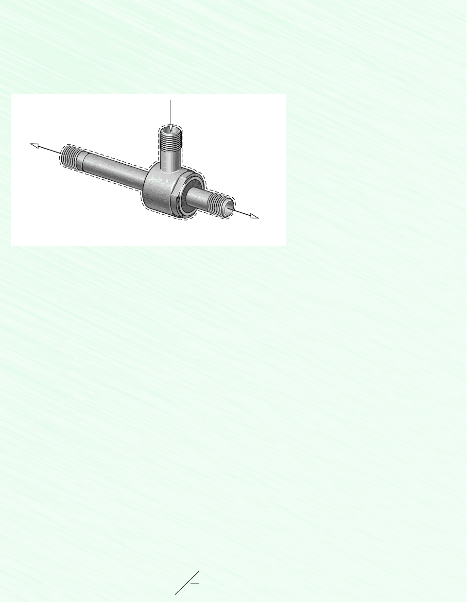
236 Chapter 6 Using Entropy
SOLUTION
Known: Data are provided for a device that at steady state produces hot and cold streams of air from a single stream of air
at an intermediate temperature without energy transfers by work or heat.
Find: Evaluate whether the device can operate as claimed.
Schematic and Given Data:
❶
❷
T
1
= 21°C
p
1
= 5.1 bars
T
3
= 18°C
p
3
= 1 bar
T
2
= 79°C
p
2
= 1 bar
1
3
2
Inlet
Cold outlet
Hot outlet
Figure E6.7
Assumptions:
1. The control volume shown on the accompanying sketch is at steady state.
2. For the control volume, and .
3. Changes in the kinetic and potential energies from inlet to exit can be ignored.
4. The air is modeled as an ideal gas with constant c
p
Analysis: For the device to operate as claimed, the conservation of mass and energy principles must be satisfied. The sec-
ond law of thermodynamics also must be satisfied; and in particular the rate of entropy production cannot be negative. Ac-
cordingly, the mass, energy and entropy rate balances are considered in turn.
With assumptions 1–3, the mass and energy rate balances reduce, respectively, to
Since , it follows from the mass rate balance that . By combining the mass and energy rate balances
and evaluating changes in specific enthalpy using constant c
p
, the energy rate balance is also satisfied. That is
Accordingly, with the given data the conservation of mass and energy principles are satisfied.
Since no significant heat transfer occurs, the entropy rate balance at steady state reads
0
a
j
Q
#
j
T
j
0
m
#
1
s
1
m
#
2
s
2
m
#
3
s
3
s
#
cv
0
0.411052 0.61702
0.4m
#
1
c
p
1T
1
T
2
2 0.6m
#
1
c
p
1T
1
T
3
2
m
#
2
1h
1
h
2
2 m
#
3
1h
1
h
3
2
0 1m
#
2
m
#
3
2
h
1
m
#
2
h
2
m
#
3
h
3
m
#
2
0.4m
#
1
m
#
3
0.6m
#
1
0 m
#
1
h
1
m
#
2
h
2
m
#
3
h
3
m
#
1
m
#
2
m
#
3
1.0 kJ/kg
#
K.
Q
#
cv
0W
#
cv
0

6.6 Entropy Rate Balance for Control Volumes 237
Combining the mass and entropy rate balances
Solving for and using Eq. 6.23 to evaluate changes in specific entropy
Thus, the second law of thermodynamics is also satisfied.
On the basis of this evaluation, the inventor’s claim does not violate principles of thermodynamics.
Since the specific heat c
p
of air varies little over the temperature interval from 0 to 79C, c
p
can be taken as constant.
From Table A-20, c
p
Since temperature differences are involved in this calculation, the temperatures can be either in C or K.
In this calculation involving temperature ratios, the temperatures must be in K.
If the value of the rate of entropy production had been negative or zero, the claim would be rejected. A negative value is
impossible by the second law and a zero value would indicate operation without irreversibilities.
Such devices do exist. They are known as vortex tubes and are used in industry for spot cooling.
1.0 kJ/kg
#
K.
0.454 kJ/kg
#
°K
0.6 ca1.0
kJ
kg
#
°K
b
ln
255
294
a
8.314
28.97
kJ
kg
#
°K
b
ln
1
5.0
d
0.4 ca1.0
kJ
kg
#
K
b
ln
352
294
a
8.314
28.97
kJ
kg
#
°K
b
ln
1
5.0
d
s
#
cv
m
#
1
0.4 cc
p
ln
T
2
T
1
R ln
p
2
p
1
d 0.6 cc
p
ln
T
3
T
1
R ln
p
3
p
1
d
s
#
cv
m
#
1
0.4m
#
1
1s
1
s
2
2 0.6m
#
1
1s
1
s
3
2 s
#
cv
m
#
2
1s
1
s
2
2 m
#
3
1s
1
s
3
2 s
#
cv
0 1m
#
2
m
#
3
2s
1
m
#
2
s
2
m
#
3
s
3
s
#
cv
❶
❷
❸
❹
❺
❸
❹
❺
In Example 6.8, we evaluate and compare the rates of entropy production for three com-
ponents of a heat pump system. Heat pumps are considered in detail in Chap. 10.
EXAMPLE 6.8 Entropy Production in Heat Pump Components
Components of a heat pump for supplying heated air to a dwelling are shown in the schematic below. At steady state,
Refrigerant 22 enters the compressor at 5C, 3.5 bar and is compressed adiabatically to 75C, 14 bar. From the com-
pressor, the refrigerant passes through the condenser, where it condenses to liquid at 28C, 14 bar. The refrigerant then
expands through a throttling valve to 3.5 bar. The states of the refrigerant are shown on the accompanying T–s diagram.
Return air from the dwelling enters the condenser at 20C, 1 bar with a volumetric flow rate of 0.42 m
3
/s and exits at
50C with a negligible change in pressure. Using the ideal gas model for the air and neglecting kinetic and potential en-
ergy effects,
(a) determine the rates of entropy production, in kW/K, for control volumes enclosing the condenser,
compressor, and expansion valve, respectively. (b) Discuss the sources of irreversibility in the components considered in
part (a).
SOLUTION
Known: Refrigerant 22 is compressed adiabatically, condensed by heat transfer to air passing through a heat exchanger, and
then expanded through a throttling valve. Steady-state operating data are known.
Find: Determine the entropy production rates for control volumes enclosing the condenser, compressor, and expansion valve,
respectively, and discuss the sources of irreversibility in these components.
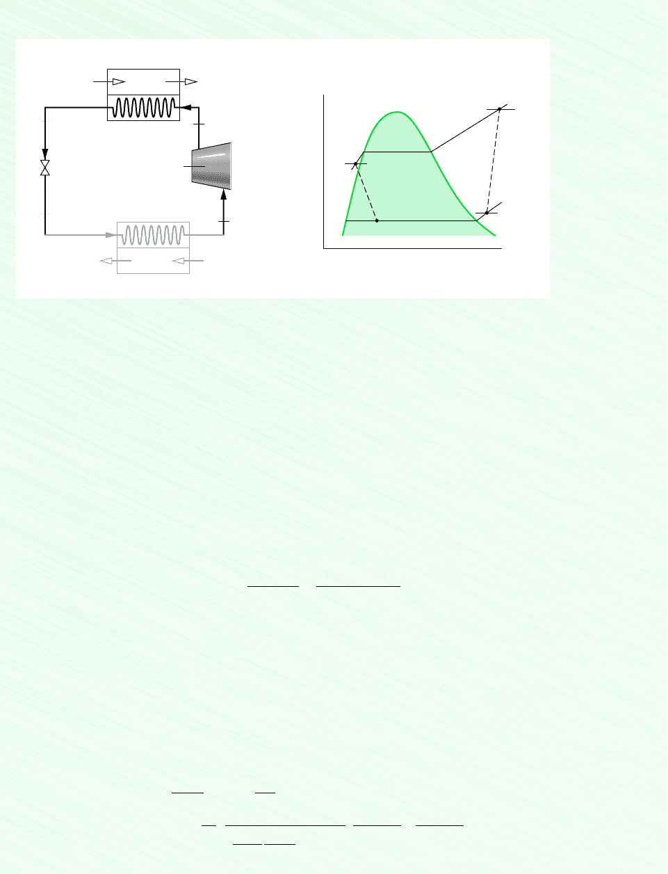
238 Chapter 6 Using Entropy
Schematic and Given Data:
T
s
3
4
1
2
75°C
–5°C
28°C
14 bar
3.5 bar
56
Expansion
valve
3
4
p
4
= 3.5 bar
p
3
= 14 bar
T
3
= 28°C
Condenser
Indoor return air
T
5
= 20°C
p
5
= 1 bar
(AV)
5
= 0.42 m
3
/s
1
2
T
1
= –5°C
p
1
= 3.5 bar
p
2
= 14 bar
T
2
= 75°C
Supply air
T
6
= 50°C
p
6
= 1 bar
Evaporator
Outdoor air
Compressor
Assumptions:
1. Each component is analyzed as a control volume at steady state.
2. The compressor operates adiabatically, and the expansion across the valve is a throttling process.
3. For the control volume enclosing the condenser, and .
4. Kinetic and potential energy effects can be neglected.
5. The air is modeled as an ideal gas with constant c
p
Analysis:
(a) Let us begin by obtaining property data at each of the principal refrigerant states located on the accompanying schematic and
T–s diagram. At the inlet to the compressor, the refrigerant is a superheated vapor at 5C, 3.5 bar, so from Table A-9,
s
1
Similarly, at state 2, the refrigerant is a superheated vapor at 75C, 14 bar, so interpolating in Table A-9
gives s
2
and h
2
294.17 kJ/kg.
State 3 is compressed liquid at 28C, 14 bar. From Table A-7, s
3
s
f
(28C) and h
3
h
f
(28C) 79.05 kJ/kg.
The expansion through the valve is a throttling process, so h
3
h
4
. Using data from Table A-8, the quality at state 4 is
and the specific entropy is
Condenser.
Consider the control volume enclosing the condenser. With assumptions 1 and 3, the entropy rate balance reduces to
To evaluate requires the two mass flow rates, and , and the change in specific entropy for the air. These are ob-
tained next.
Evaluating the mass flow rate of air using the ideal gas model (assumption 5)
a0.42
m
3
s
b
11 bar2
a
8.314
28.97
kJ
kg
#
K
b 1293 K2
`
10
5
N/m
2
1 bar
`
`
1 kJ
10
3
N
#
m
` 0.5 kg/s
m
#
air
1AV2
5
v
5
1AV2
5
p
5
RT
5
m
#
ref
m
#
air
s
#
cond
0 m
#
ref
1s
2
s
3
2 m
#
air
1s
5
s
6
2 s
#
cond
s
4
s
f4
x
4
1s
g4
s
f4
2 0.1328 0.21610.9431 0.13282 0.3078 kJ/kg
#
K
x
4
1h
4
h
f4
2
1h
fg
2
4
179.05 33.092
1212.912
0.216
0.2936 kJ/kg
#
K
0.98225 kJ/kg
#
K
0.9572 kJ/kg
#
K.
1.005 kJ/kg
#
K.
Q
#
cv
0W
#
cv
0
Figure E6.8
❶

6.6 Entropy Rate Balance for Control Volumes 239
The refrigerant mass flow rate is determined using an energy balance for the control volume enclosing the condenser together
with assumptions 1, 3, and 4 to obtain
With assumption 5, h
6
h
5
c
p
(T
6
T
5
). Inserting values
Using Eq. 6.23, the change in specific entropy of the air is
Finally, solving the entropy balance for and inserting values
Compressor.
For the control volume enclosing the compressor, the entropy rate balance reduces with assumptions 1 and 3 to
or
Valve.
Finally, for the control volume enclosing the throttling valve, the entropy rate balance reduces to
Solving for and inserting values
(b) The following table summarizes, in rank order, the calculated entropy production rates:
Component
.
cv
(kW/K)
compressor 17.5 10
4
valve 9.94 10
4
condenser 7.95 10
4
9.94 10
4
kW/K
s
#
valve
m
#
ref
1s
4
s
3
2 a0.07
kg
s
b 10.3078 0.29362 a
kJ
kg
#
K
b `
1 kW
1 kJ/s
`
s
#
valve
0 m
#
ref
1s
3
s
4
2 s
#
valve
17.5 10
4
kW/K
a0.07
kg
s
b 10.98225 0.95722 a
kJ
kg
#
K
b
`
1
kW
1 kJ/s
`
s
#
comp
m
#
ref
1s
2
s
1
2
0 m
#
ref
1s
1
s
2
2 s
#
comp
7.95 10
4
kW
K
ca0.07
kg
s
b 10.2936 0.982252
kJ
kg
#
K
10.52 10.0982d `
1 kW
1 kJ/s
`
s
#
cond
m
#
ref
1s
3
s
2
2 m
#
air
1s
6
s
5
2
s
#
cond
a1.005
kJ
kg
#
K
b
ln a
323
293
b R ln
a
1.0
1.0
b
0
0.098 kJ/kg
#
K
s
6
s
5
c
p
ln
T
6
T
5
R ln
p
6
p
5
m
#
ref
a0.5
kg
s
b a1.005
kJ
kg
#
K
b 1323 2932K
1294 .17 79 .052 kJ/kg
0.07 kg/s
m
#
ref
m
#
air
1h
6
h
5
2
1h
2
h
3
2
❷
❸

240 Chapter 6 Using Entropy
Entropy production in the compressor is due to fluid friction, mechanical friction of the moving parts, and internal heat trans-
fer. For the valve, the irreversibility is primarily due to fluid friction accompanying the expansion across the valve. The prin-
cipal source of irreversibility in the condenser is the temperature difference between the air and refrigerant streams. In this
example, there are no pressure drops for either stream passing through the condenser, but slight pressure drops due to fluid
friction would normally contribute to the irreversibility of condensers. The evaporator lightly shown in Fig. E6.8 has not been
analyzed.
Due to the relatively small temperature change of the air, the specific heat c
p
can be taken as constant at the average of
the inlet and exit air temperatures.
Temperatures in K are used to evaluate but since a temperature difference is involved the same result would be ob-
tained if temperatures in C were used. Temperatures in K must be used when a temperature ratio is involved, as in Eq. 6.23
used to evaluate s
6
s
5
.
By focusing attention on reducing irreversibilities at the sites with the highest entropy production rates, thermodynamic
improvements may be possible. However, costs and other constraints must be considered, and can be overriding.
m
#
ref
,
❶
❷
❸
6.7 Isentropic Processes
The term isentropic means constant entropy. Isentropic processes are encountered in many
subsequent discussions. The object of the present section is to explain how properties are re-
lated at any two states of a process in which there is no change in specific entropy.
6.7.1 General Considerations
The properties at states having the same specific entropy can be related using the graphical
and tabular property data discussed in Sec. 6.3.1. For example, as illustrated by Fig. 6.9, tem-
perature–entropy and enthalpy–entropy diagrams are particularly convenient for determining
properties at states having the same value of specific entropy. All states on a vertical line
passing through a given state have the same entropy. If state 1 on Fig. 6.9 is fixed by pres-
sure p
1
and temperature T
1
, states 2 and 3 are readily located once one additional property,
such as pressure or temperature, is specified. The values of several other properties at states
2 and 3 can then be read directly from the figures.
Tabular data also can be used to relate two states having the same specific entropy. For
the case shown in Fig. 6.9, the specific entropy at state 1 could be determined from the
superheated vapor table. Then, with s
2
s
1
and one other property value, such as p
2
or T
2
,
Figure 6.9 T–s and h–s diagrams showing states having the same value of
specific entropy.
T
1
2
3
p
1
T
1
p
2
p
3
T
2
T
3
h
ss
1
2
3
p
1
T
1
p
2
p
3
T
2
T
3

6.7 Isentropic Processes 241
state 2 could be located in the superheated vapor table. The values of the properties v, u, and
h at state 2 can then be read from the table. An illustration of this procedure is given in Sec.
6.3.1. Note that state 3 falls in the two-phase liquid–vapor regions of Fig. 6.9. Since s
3
s
1
,
the quality at state 3 could be determined using Eq. 6.6. With the quality known, other prop-
erties such as v, u, and h could then be evaluated. Computer retrieval of entropy data pro-
vides an alternative to tabular data.
6.7.2 Using the Ideal Gas Model
Figure 6.10 shows two states of an ideal gas having the same value of specific entropy. Let
us consider relations among pressure, specific volume, and temperature at these states, first
using the ideal gas tables and then assuming specific heats are constant.
IDEAL GAS TABLES
For two states having the same specific entropy, Eq. 6.21a reduces to
(6.42a)
Equation 6.42a involves four property values: p
1
, T
1
, p
2
, and T
2
. If any three are known, the
fourth can be determined. If, for example, the temperature at state 1 and the pressure ratio
p
2
p
1
are known, the temperature at state 2 can be determined from
(6.42b)
Since T
1
is known, s(T
1
) would be obtained from the appropriate table, the value of s(T
2
)
would be calculated, and temperature T
2
would then be determined by interpolation. If p
1
,
T
1
, and T
2
are specified and the pressure at state 2 is the unknown, Eq. 6.42a would be solved
to obtain
(6.42c)
Equations 6.42 can be used when s (or ) data are known, as for the gases of Tables A-22
and A-23.
AIR. For the special case of air modeled as an ideal gas, Eq. 6.42c provides the basis for
an alternative tabular approach for relating the temperatures and pressures at two states having
the same specific entropy. To introduce this, rewrite the equation as
The quantity exp[s(T )R] appearing in this expression is solely a function of temperature,
and is given the symbol p
r
(T ). A tabulation of p
r
versus temperature for air is provided in
Tables A-22.
1
In terms of the function p
r
, the last equation becomes
(6.43)
p
2
p
1
p
r2
p
r1
1s
1
s
2
, air only2
p
2
p
1
exp3s°1T
2
2
R4
exp3s°1T
1
2
R4
s°
p
2
p
1
exp c
s°1T
2
2 s°1T
1
2
R
d
s°1T
2
2 s°1T
1
2 R ln
p
2
p
1
0 s°1T
2
2 s°1T
1
2 R ln
p
2
p
1
Figure 6.10 Two
states of an ideal gas
where s
2
s
1
.
T
s
2
1
v
2
v
1
p
1
T
1
p
2
T
2
1
The values of p
r
determined with this definition are inconveniently large, so they are divided by a scale factor
before tabulating to give a convenient range of numbers.

242 Chapter 6 Using Entropy
where p
r1
p
r
(T
1
) and p
r2
p
r
(T
2
). The function p
r
is sometimes called the relative pres-
sure. Observe that p
r
is not truly a pressure, so the name relative pressure is misleading. Also,
be careful not to confuse p
r
with the reduced pressure of the compressibility diagram.
A relation between specific volumes and temperatures for two states of air having the
same specific entropy can also be developed. With the ideal gas equation of state, v RTp,
the ratio of the specific volumes is
Then, since the two states have the same specific entropy, Eq. 6.43 can be introduced to give
The ratio RTp
r
(T ) appearing on the right side of the last equation is solely a function of
temperature, and is given the symbol v
r
(T ). Values of v
r
for air are tabulated versus tem-
perature in Tables A-22. In terms of the function v
r
, the last equation becomes
(6.44)
where v
r1
v
r
(T
1
) and v
r2
v
r
(T
2
). The function v
r
is sometimes called the relative volume.
Despite the name given to it, v
r
(T ) is not truly a volume. Also, be careful not to confuse it
with the pseudoreduced specific volume of the compressibility diagram.
ASSUMING CONSTANT SPECIFIC HEATS
Let us consider next how properties are related for isentropic processes of an ideal gas when
the specific heats are constants. For any such case, Eqs. 6.22 and 6.23 reduce to the equations
Introducing the ideal gas relations
(3.47)
these equations can be solved, respectively, to give
(6.45)
(6.46)
The following relation can be obtained by eliminating the temperature ratio from
Eqs. 6.45 and 6.46:
(6.47)
p
2
p
1
a
v
1
v
2
b
k
1s
1
s
2
, constant k2
T
2
T
1
a
v
1
v
2
b
k1
1s
1
s
2
, constant k2
T
2
T
1
a
p
2
p
1
b
1k 12
k
1s
1
s
2
, constant k2
c
p
kR
k 1
,
c
v
R
k 1
0 c
v
ln
T
2
T
1
R ln
v
2
v
1
0 c
p
ln
T
2
T
1
R ln
p
2
p
1
v
2
v
1
v
r2
v
r1
1s
1
s
2
, air only2
v
2
v
1
c
RT
2
p
r
1T
2
2
d c
p
r
1T
1
2
RT
1
d
v
2
v
1
a
RT
2
p
2
b a
p
1
RT
1
b
METHODOLOGY
UPDATE
When applying the
software IT to relate two
states of an ideal gas
having the same value of
specific entropy, note that
IT returns specific entropy
directly and does not
employ the special
functions s, p
r
and v
r
.

6.7 Isentropic Processes 243
Figure 6.11 Polytropic processes on p–v and T–s diagrams.
p
v
s
=
c
o
n
s
t
a
n
t
T
=
c
o
n
s
t
a
n
t
n = –1
n = 0
n = 1
n = k
n = ± ∞
n = ± ∞
T
s
v
=
c
o
n
s
t
a
n
t
p
=
c
o
n
s
t
a
n
t
n = –1
n = 0
n = 1
n = k
EXAMPLE 6.9 Isentropic Process of Air
Air undergoes an isentropic process from p
1
1 bar, T
1
300K to a final state where the temperature is T
2
650K.
Employing the ideal gas model, determine the final pressure p
2
, in atm. Solve using (a) p
r
data from Table A-22 (b) Int-
eractive Thermodynamics: IT, and (c) a constant specific heat ratio k evaluated at the mean temperature, 475K, from Table
A-20.
SOLUTION
Known: Air undergoes an isentropic process from a state where pressure and temperature are known to a state where the
temperature is specified.
Find: Determine the final pressure using (a) p
r
data, (b) IT, and (c) a constant value for the specific heat ratio k.
Schematic and Given Data:
Assumptions:
1. A quantity of air as the system undergoes an isentropic process.
2. The air can be modeled as an ideal gas.
3. In part (c) the specific heat ratio is constant.
2
1
p
2
= ?
T
2
= 650 K
p
1
= 1 bar
T
1
= 300 Κ
T
s
Figure E6.9
From the form of Eq. 6.47, it can be concluded that a polytropic process pv
k
constant
of an ideal gas with constant k is an isentropic process. We noted in Sec. 3.8 that a poly-
tropic process of an ideal gas for which n 1 is an isothermal (constant-temperature) process.
For any fluid, n 0 corresponds to an isobaric (constant-pressure) process and n
corresponds to an isometric (constant-volume) process. Polytropic processes corresponding
to these values of n are shown in Fig. 6.11 on p–v and T–s diagrams.
The foregoing means for evaluating data for an isentropic process of air modeled as an
ideal gas are considered in the next example.

244 Chapter 6 Using Entropy
Analysis:
(a) The pressures and temperatures at two states of an ideal gas having the same specific entropy are related by Eq. 6.43
Solving
With p
r
values from Table A-22
(b) The IT solution follows:
T1 = 300 // K
p1 = 1 // atm
T2 = 650 // K
s_TP(“Air“,T1,p1) = s_TP(“Air”,T2,p2)
// Result: p2 = 15.77 bar
(c) When the specific heat ratio k is assumed constant, the temperatures and pressures at two states of an ideal gas having
the same specific entropy are related by Eq. 6.45. Thus
From Table A-20 at 202C (475K), k 1.39. Inserting values into the above expression
IT returns a value for p
2
even though it is an implicit variable in the argument of the specific entropy function. Also note
that IT returns values for specific entropy directly and does not employ special functions such as s, p
r
and v
r
.
The close agreement between the answer obtained in part (c) and that of parts (a), (b) can be attributed to the use of an
appropriate value for the specific heat ratio k.
p
2
11 bar2 a
650
300
b
1.39
0.39
15.81 bar
p
2
p
1
a
T
2
T
1
b
k
1k 12
p 11 bar2
21.86
1.3860
15.77 bars
p
2
p
1
p
r2
p
r1
p
2
p
1
p
r2
p
r1
❷
❶
❶
❷
Another illustration of an isentropic process of an ideal gas is provided in the next ex-
ample dealing with air leaking from a tank.
EXAMPLE 6.10 Air Leaking from a Tank
A rigid, well-insulated tank is filled initially with 5 kg of air at a pressure of 5 bar and a temperature of 500 K. A leak de-
velops, and air slowly escapes until the pressure of the air remaining in the tank is 1 bar. Employing the ideal gas model, de-
termine the amount of mass remaining in the tank and its temperature.
SOLUTION
Known: A leak develops in a rigid, insulated tank initially containing air at a known state. Air slowly escapes until the pres-
sure in the tank is reduced to a specified value.
Find: Determine the amount of mass remaining in the tank and its temperature.

6.7 Isentropic Processes 245
Schematic and Given Data:
Analysis: With the ideal gas equation of state, the mass initially in the tank that remains in the tank at the end of the process is
where p
2
and T
2
are the final pressure and temperature, respectively. Similarly, the initial amount of mass within the tank, m
1
,is
where p
1
and T
1
are the initial pressure and temperature, respectively. Eliminating volume between these two expressions, the
mass of the system is
Except for the final temperature of the air remaining in the tank, T
2
, all required values are known. The remainder of the so-
lution mainly concerns the evaluation of T
2
.
For the closed system under consideration, there are no significant irreversibilities (assumption 3), and no heat transfer oc-
curs (assumption 2). Accordingly, the entropy balance reduces to
Since the system mass remains constant, S m
2
s,so
That is, the initial and final states of the system have the same value of specific entropy.
Using Eq. 6.43
where p
1
5 bar and p
2
1 bar. With p
r1
8.411 from Table A-22 at 500 K, the previous equation gives p
r2
1.6822.
Using this to interpolate in Table A-22, T
2
317 K.
Finally, inserting values into the expression for system mass
This problem also could be solved by considering a control volume enclosing the tank. The state of the control volume
would change with time as air escapes. The details of the analysis are left as an exercise.
m
2
a
1 bar
5 bar
b a
500 K
317 K
b 15 kg2 1.58 kg
p
r2
a
p
2
p
1
b p
r1
¢s 0
¢S
2
1
a
dQ
T
b
b
0
s
0
0
m
2
a
p
2
p
1
b a
T
1
T
2
b m
1
m
1
p
1
V
1R
M2 T
1
m
2
p
2
V
1R
M2 T
2
Slow leak
Mass initially in the
tank that escapes
Mass initially
in the tank that
remains in the tank
System boundary
Initial condition of tank
Assumptions:
1. As shown on the accompanying sketch, the closed system is the mass
initially in the tank that remains in the tank.
2. There is no significant heat transfer between the system and its
surroundings.
3. Irreversibilities within the tank can be ignored as the air slowly
escapes.
4. The air is modeled as an ideal gas.
Figure E6.10
❶
❶
